Week 14
composites
Assignment
- design and make a 3D mold (~ft2), and produce a fiber composite part in it
Week workflow
Here is how I see the week's flow :
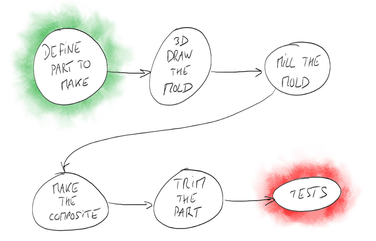
Flow chart for this week
Table of content :
- Drawing the Mold
- Milling the Mold
- Making the composite
- Demolding and Trimming the part
- Testing
- Source files
STEPS
Drawing the Mold
Here at the greenfablab we always need wheelbarrows. We have a few, but some of them are broken. It would be nice to repair them.
They are broken mainly because they were badly designed or because they were designed to break.
My idea is then to make the container part of the wheelbarrow.
But I will start to make a 200 x 100mm coupon
I want to use natural fiber (burlap) and epoxy resin.
As recommended, we'll aim for a 50/50 fiber/resin ratio.
I'm assuming the fiber is 1 mm thick and I want to use 6 plies of fiber.
So according to the picture below, our composite will be 6 + 7 = 13 mm.
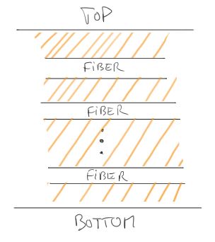
Diagram of composite composition
I will use a two parts mold. So compression will be made by clamping the two parts together.
I start drawing the bottom part :

The bottom mold part in SolidWorks
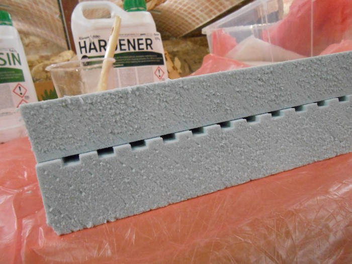
the teeth are for letting the resin to be squished out.
The top part is then drawn.
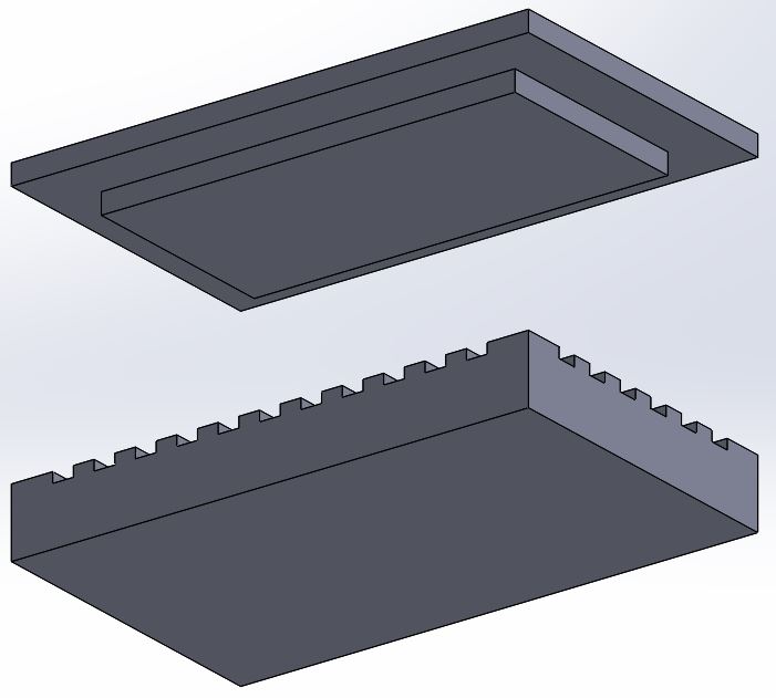
The top and bottom molding parts in SolidWork
Here are sections of the two parts :
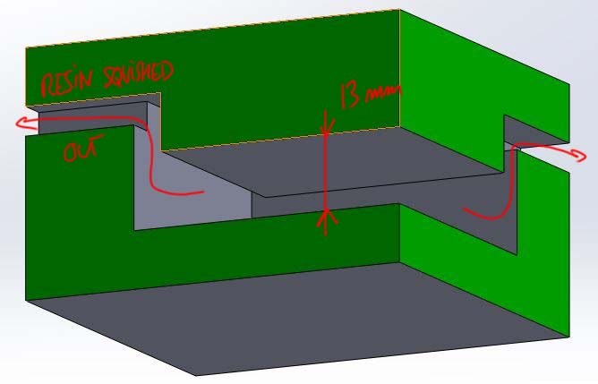
Sections of the mold
When exporting from SolidWorks to another 3D software it's nice to be able to have the part oriented exactly how we want it to be.
That can be done with the Coordinate System feature :
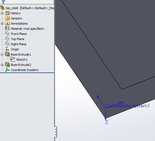
Rhino Coordinate system in SolidWorks
And selecting it in the export options
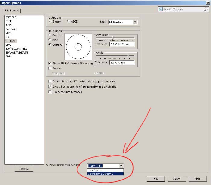
Exporting accroding to custom coordinate system
In Rhino, more specifically RhinoCAM, we have three milling operations :

The three milling operations
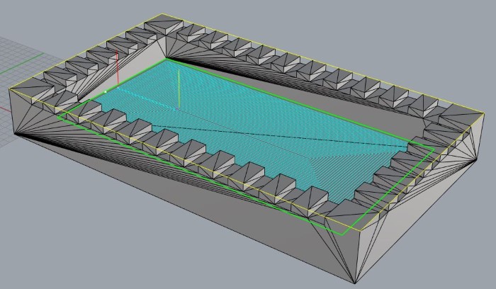
Here is the toolpath of the roughing operation :
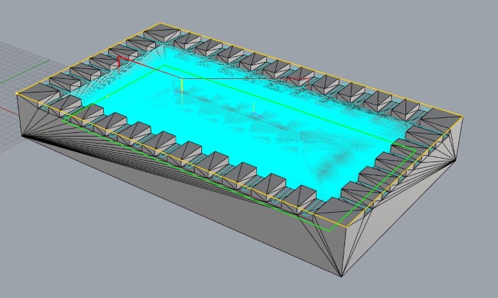
Roughing
the horizontal finishing :
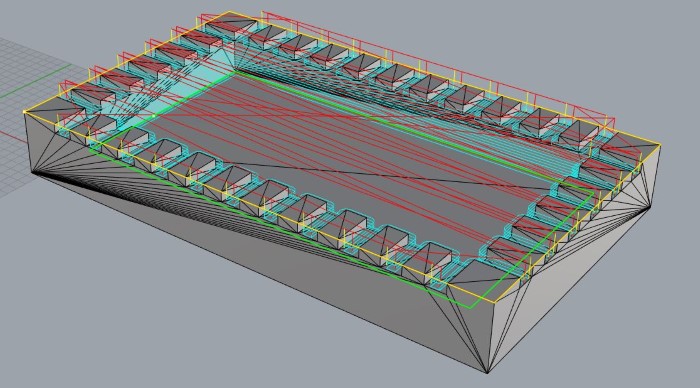
horizontal finishing
and, at last, the pocketing :
pocketing
When I started to mill (see next section), it was taking too much time compared to the capability of milling in rigid foam, which should be fast.
One speed improvements was to change the overlap from 25 to 75 :
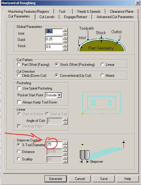
Increasing the Stepover parameter
As we can see, there is way less tool traveling :
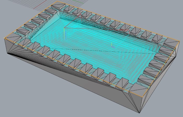
result of increased stepover
Milling the Mold
First I surface the foam part that I have as it's all bumpy :
Surfacing the rigidfoam stock
Another improvements for the speed is to change the ramps values :
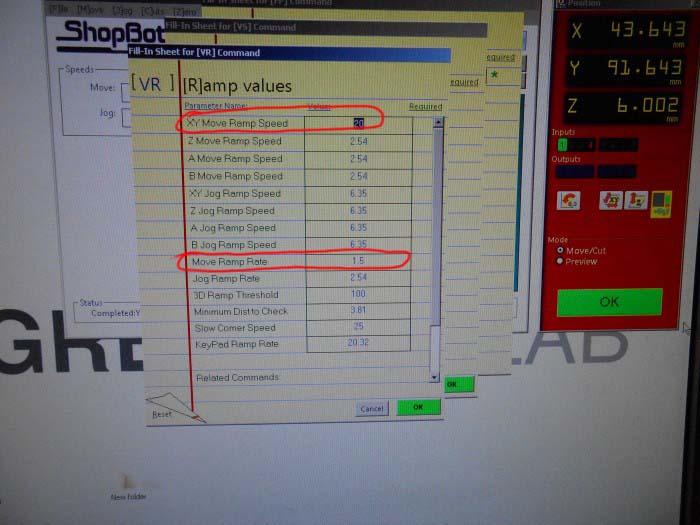
Adjusting ramp values for better speed
Then I mill the foam using the shopbot :
Rough Milling at improved speed
I do the same thing for the top mold next to this part
Then I handsaw the parts and I have my two parts mold.
Making the composite
So I'm using burlap fabric (fibers)
I need to cut 6 100x200mm pieces
I started to cut them with scissors and suddenly realized I could just lasercut them.
Here is the fabric in the laser cutter before cutting :
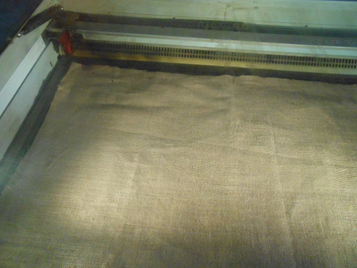
Burlap sheet
And aftert the laser cutting :
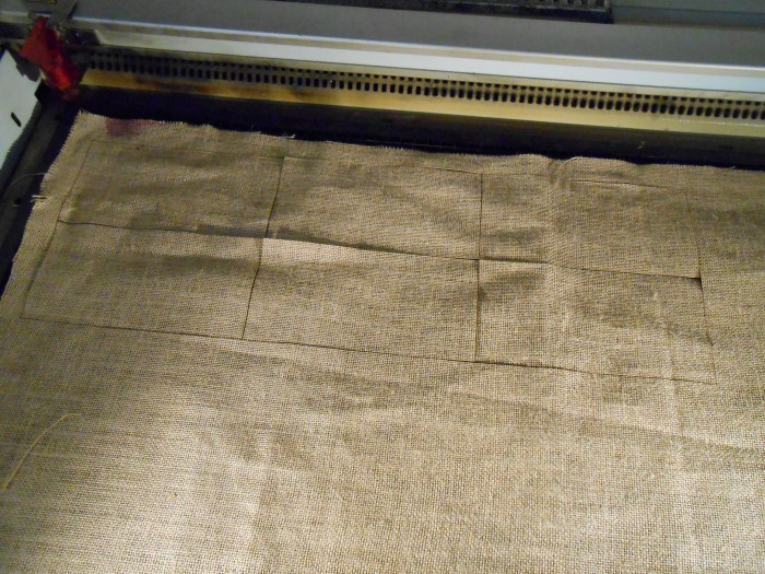
Laser cut burlap
Here are then my plies :
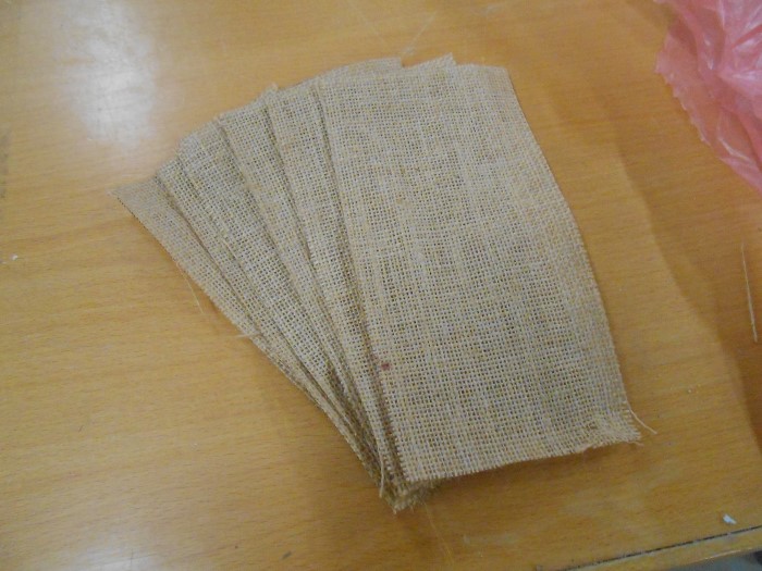
The 6 plies of the composite's fiber
I will use Epoxy resin, which comes in two products, the resin and the hardener :
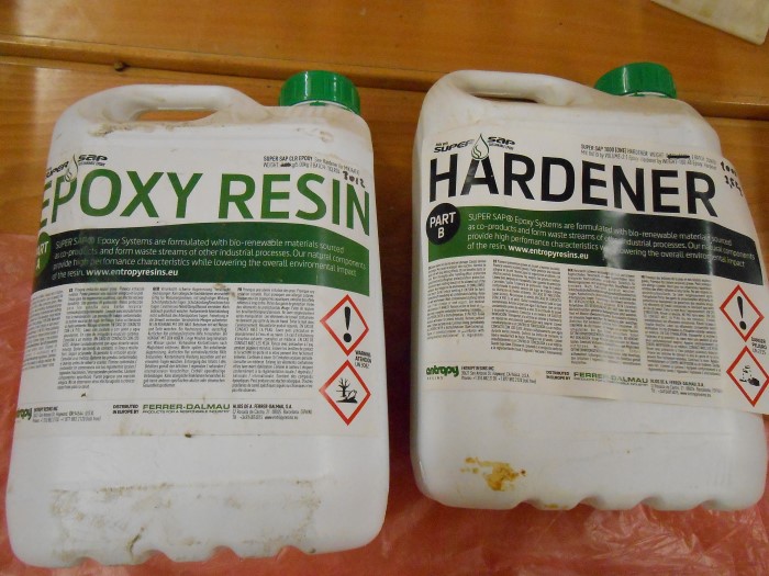
The resin and the hardener
I first tare the scale :
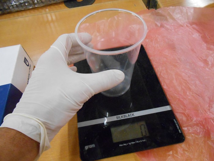
Zeroing (tare) the scale
I feel that a plastic glass of resin is enough for my coupon. So I pour some resin inside the glass :
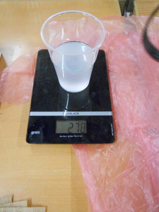
Pouring the resin
Then i made the calculation to know to what weight I need to add up hardener (2:1 resin/hardener ratio)

Calculating hardener quantity
After I poured the hardener, I mixed the two fluids together until I got an homogeneous liquid (by color) :
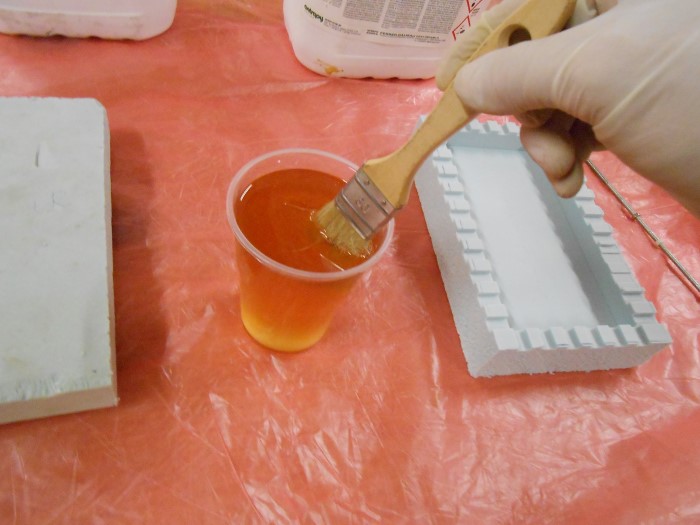
Ready matrix mix
Then I start the process of laying my fabric plies and infusing them :
Infusing the fibers
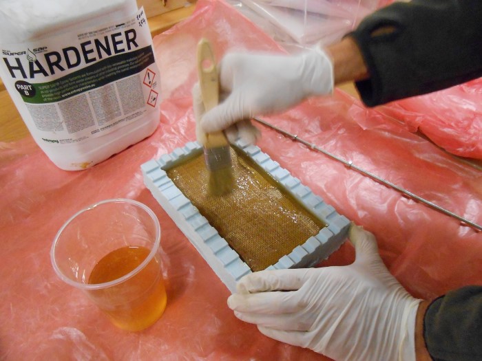
Infusion in action :
The infusion of the burlap fabric mesh with the matrix mix
Here is my composition ready to be mold-closed and compressed.
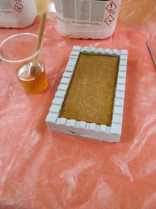
All plies infused
Closing the mold
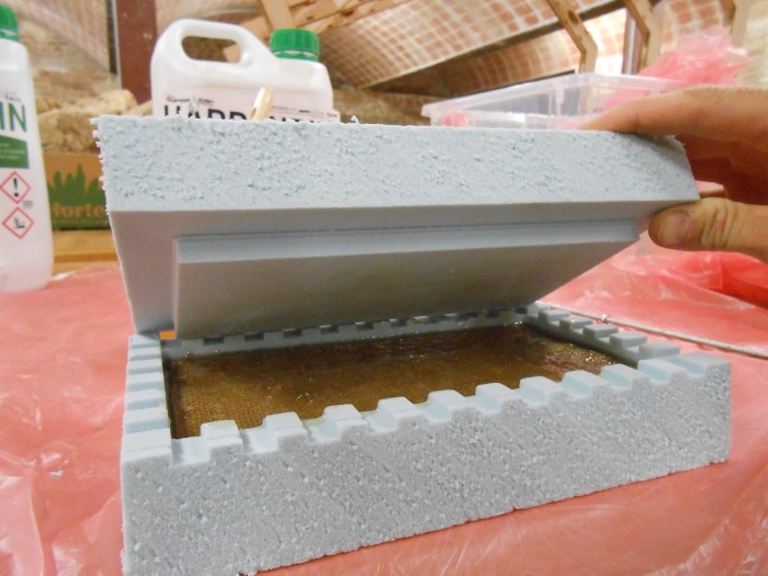
Closing the lid
Mold closed
Then I use a piece of wood to spread the pressure across the rigid foam surface and make that compression with clamps :
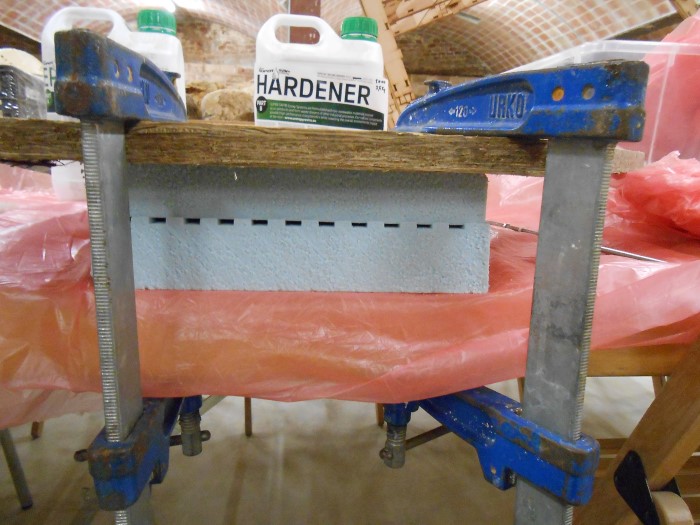
Mold clamped
After curing, we can see that the resin has been squished out of the mold through the teeth.
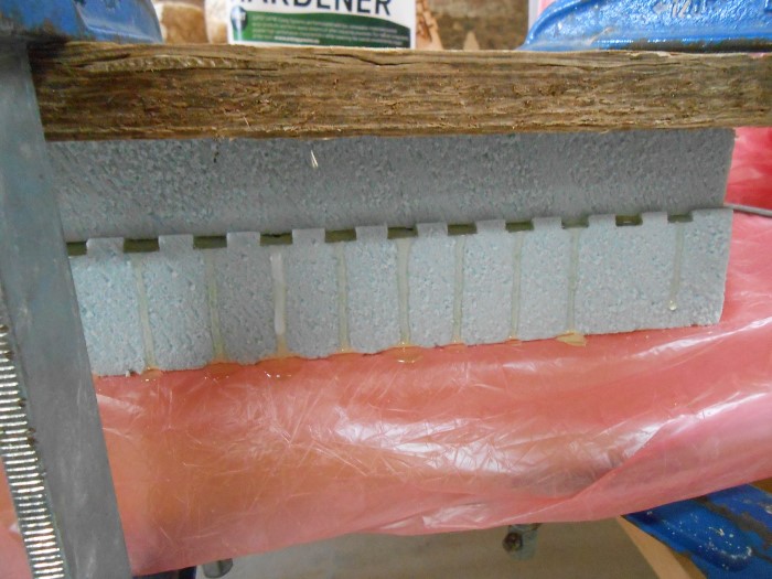
Resin squished out through teeth
I'm not sure if the chemical reaction expanses or if the rigid foam slowly shrunk under the pressure giving less and less space for the resin inside the mold.
When I measured the thickness of my coupon it was 11mm instead of 13mm so that could indeed be a shrinkage of the rigid foam.
Demolding and trimming the part
Demolding was basically breaking away the rigid foam :
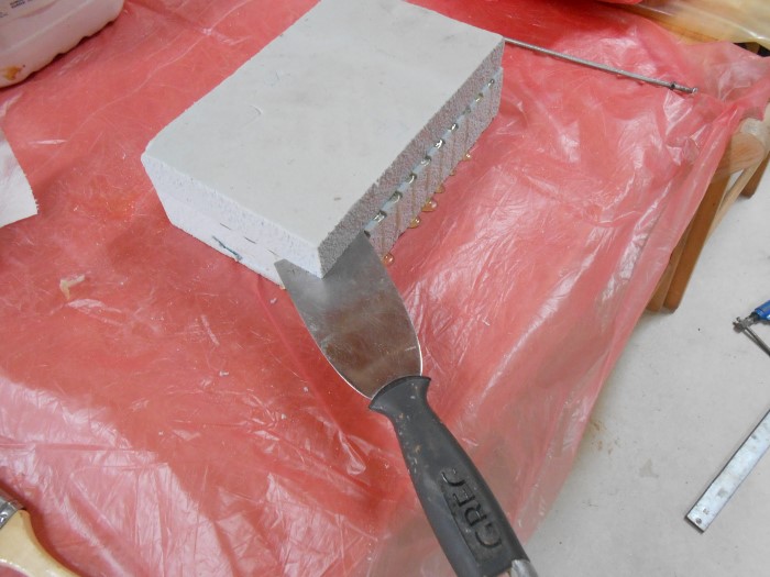
Demolding temptative
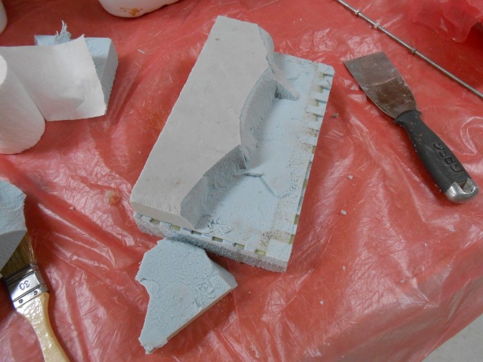
Breaking the mold away
However, I had forgotten to put mold release (vaseline) on the top part of the mold so that might have been why I had to break the top part away.
Scraping the mold away
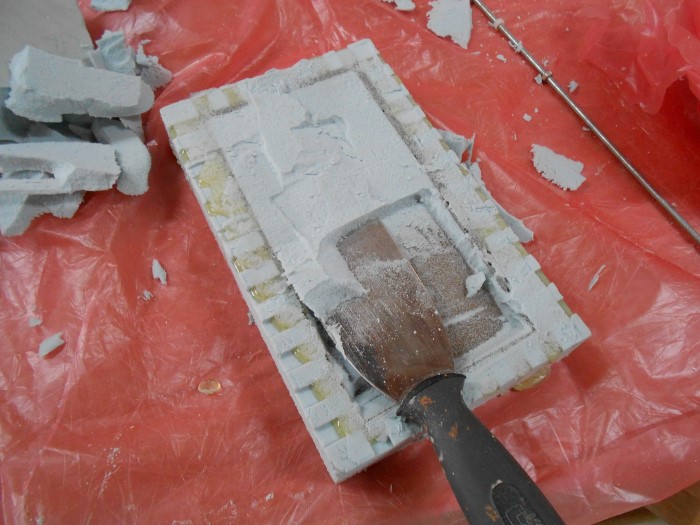
Then I generated a toolpath for trimming the composite part right into its bottom mold part :
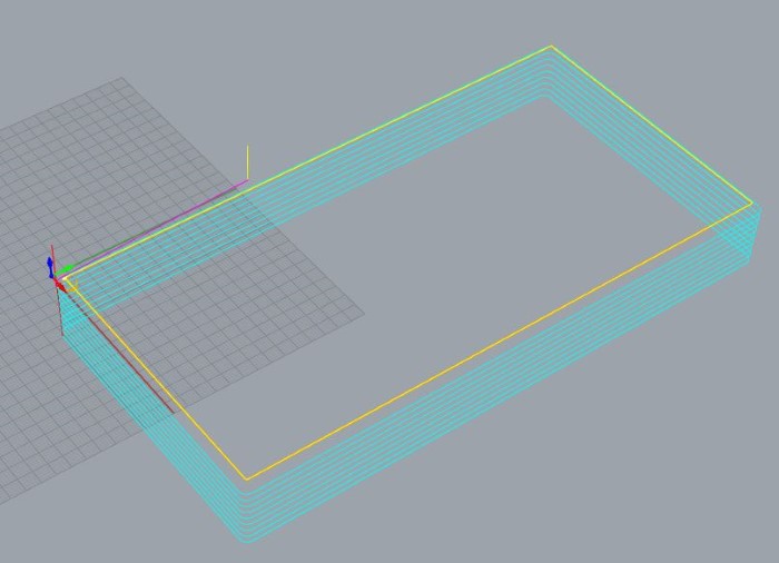
Toolpath for trimming
Trimming in action :
Trimming the part by milling the resin excess
It was indeed way easier to remove the part from the bottom mold part since I had put here vaseline (mold release)
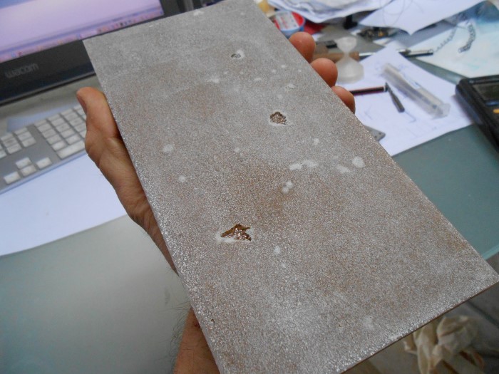
But the surface doesn't look so nice
Composite bottom
Plus I can see that I trapped air bubbles during the infusion process. So I'll have to be more careful about this for the next composites.
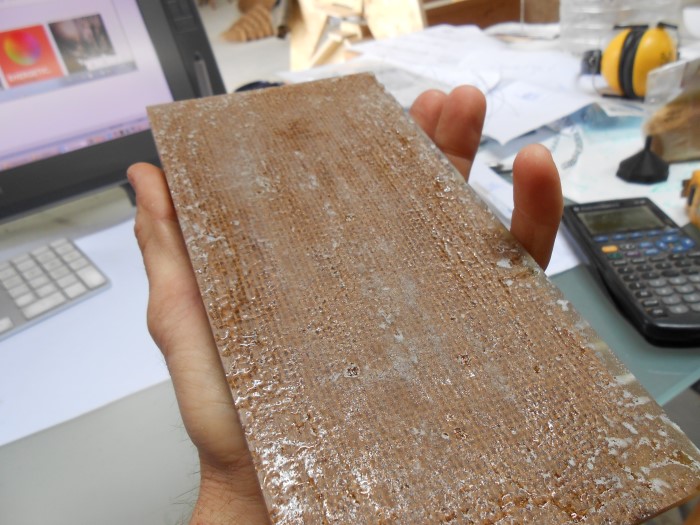
Composite top
On the side we can see my 6 plies of burlap.
We can also clearly see that the ratio is not 50/50 resin/fiber.
I really that's because I made my calculations assuming the burlap was 1mm thick which it is not, it's more .2mm
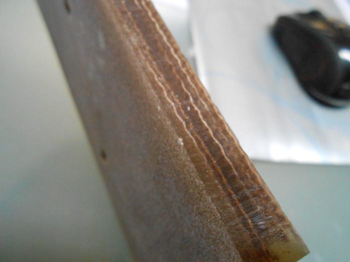
Composite side
Testing
For testing I just put my whole weight on it like this :
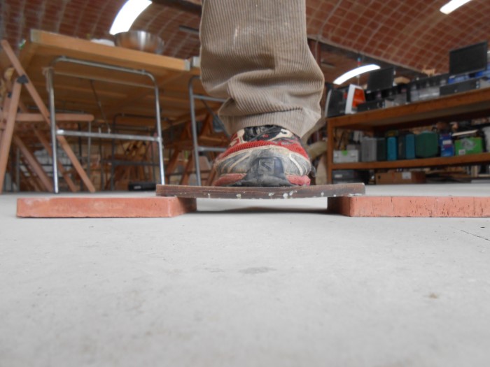
75kg on composite - traction test
And then I try Kung-fu :
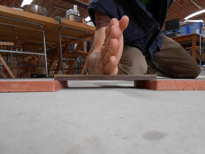
Kung-fu test
didn't break...
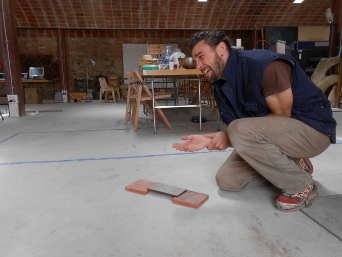
It was a stupid test
Composites are strong (and Shaolin-proofed apparently).
Source files
Here are the sources files of the projects I talked about on this page :
SolidWorks Files for composite coupon
Rhino Files (RhinoCAM) for composite coupon
Conclusion
***