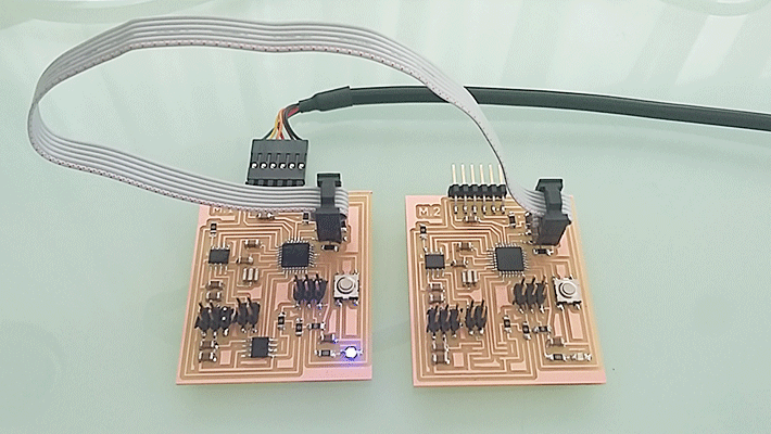
The aim for this week’s assignment was to design and build a wired &/or wireless network connecting at least two processors. As my final project was thought to be a wired network of three different motors I decided to do for this assignment the final boards (or at least try) of my final project.
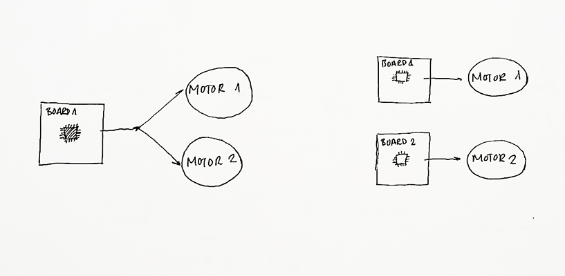
For this, I had to think of how I was going to connect the different motors. There are some ways to do so, that is to say, you can control two different motors with one processor (in one board) or separating them in two boards with two different processors. I decided to do the second one for three reasons:
• The first one is that I’m not used to programming and the first option is harder to do than the second.
• The second reason is because if I do the second one I can add as many motors as I want.
• The third is that the boards are less complicated than the first option because it only has 2 Hbridges.
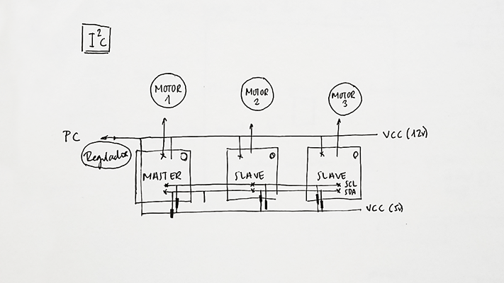
Once I decided how I was going to do the connections I had to decide again which communication protocol I was going to use. I decided to use I 2 C That is a communication protocol that allows a communication between multiples devices connected.
It is necessary an order of communication between the processors and this is achieved giving one the characteristic of “Master” and the rest the characteristic of “Slave”.
The advantages for the I 2 C are first of all that only two wires are needed, you can control the communication flow, there is a mechanism for ensure that the message has been arrived, each node has a direction with which we can communicate individually. And the disadvantages are that doesn’t allow sending and receiving information at the same time, there is not a control of the errors and it is limited up to 128 devices.
MASTER: When the master wants to talk with a slave the communication starts by bits that establish with who he wants to talk. There is another series of bits that establish if he wants them to hear the message or just an answer tothe message.
SLAVE: It responds to the message when it receive the message from the master, the slave sends a confirmation to the master saying that he has received the message and then he sends the response. The master doesn’t confirm that he has received the response from the slave.
Designing the board
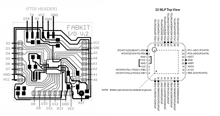
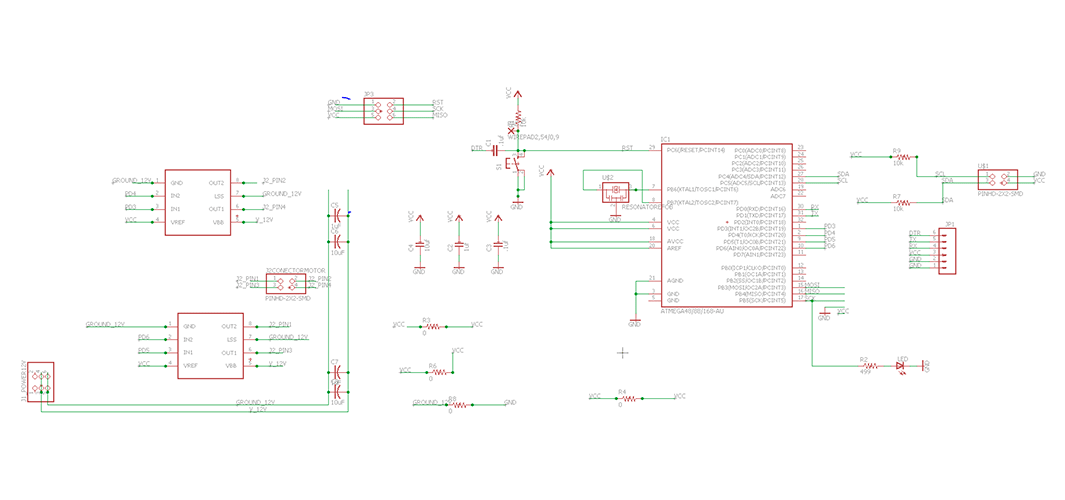
As I wanted to use the Arduino libraries (wire: master writer, master reader) and this library is not working with AtTiny 44/45 I decided to use the same processor that the Fabkit, an ATMega168 . I based the design of my motor board in the Fabkit, I erased all the elements that I didn’t need and I added the ones that my board needed, in my case I added:
• 6 pin header for programming (GND, RST, MOSI, SCK, MISO,VCC)
• 6 pin header for 12V power (VCC, VCC, GND, GND) As I did in the output assignment I only needed 4 pins but I used a 6 pin header just in case I connected in a wrong position the header in order to not breaking the board.
• 4 pin connector I 2 C (SCL, GND, SDA, VCC)
• 2 H-Bridge
With the aid of the datasheet the next step was seeing where I had to connect all this new things in the microcontroller. First of all I thought to connect my motors to the analog pins as in the output assignment (PINS 28,27) but I realize I couldn’t because these pins where needed to connect SCL and SDA so I had to connect the motors to another pins (PINS 1,2,9,10). As I put a 6 pin header for the procreation I needed to connect MISO and MOSI to its respective pins in the microcontroller.
As I wanted to mix both boards the Fabkit board and the one I made in the Output assignment I used the Eagle files. As I said before, I cleared all the elements I didn’t need and add the ones I needed and then I connected them to its pins. It was the hardest board I’ve done till the moment and I founded very difficult to put and connect every single element but at the end I was able to do it!
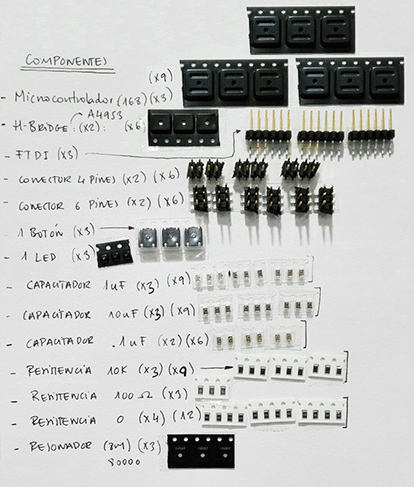
As I wanted to do three boards there were a lot of elements so I had to be very organised in order not to lose some elements. As you can see in the picture from below I did a list of the elements
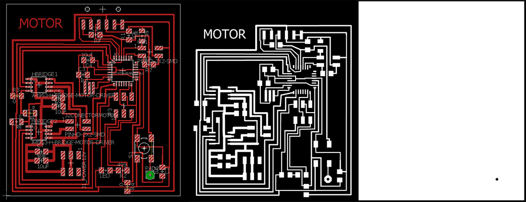
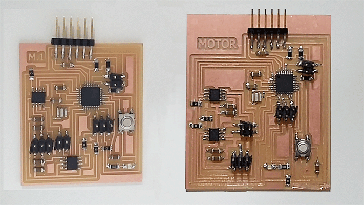
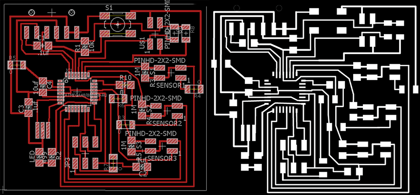
Then I milled the first board with the Rolland mill and when I checked with the multimeter if all the wiring was correct there was a shortcut in the board it gave me continuity between GND and VCC and this was a very big problem. I checked the board design in Eagle just to see if I did wrong the connections but everything was ok. I thought it was a problem with the soldering part but then I realize that my board wasn’t milled in a good way because the mill that I used was overused. I decided to redesign the board reducing the size of it.
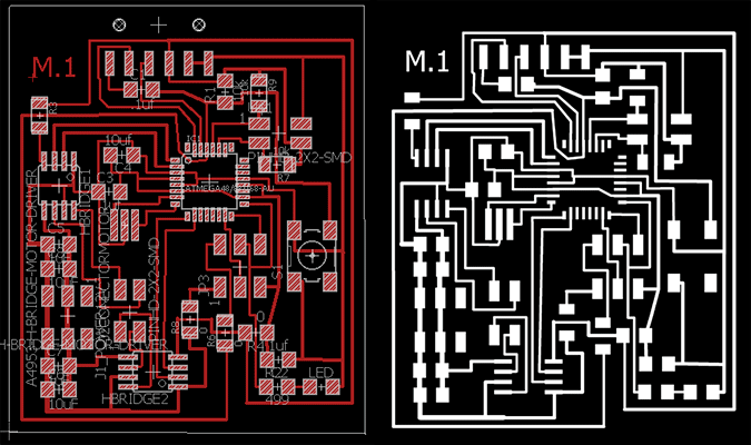
The board in the left is the new board I redisigned. As you can see in the image, the first boarm was milled in a wrong way with an overused mill.
Programming the board
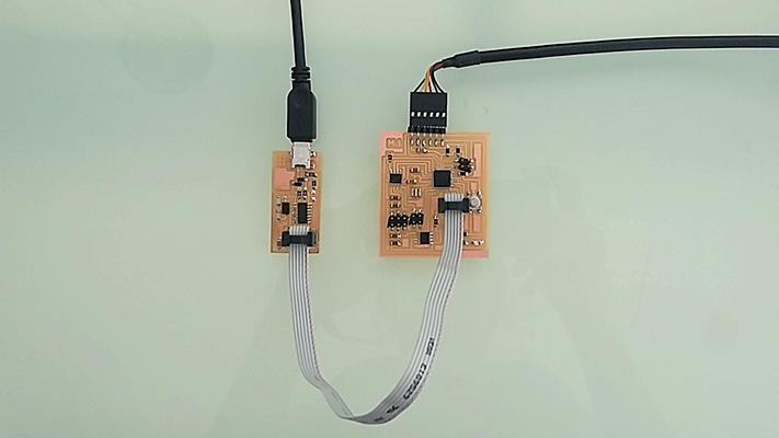
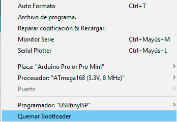
After checking that all the wiring in my new board was correct I program it with Arduino burning the bootloader. For this I had to connect my FabISP to my board, select all the options:
Board: Arduino Pro or Pro Mini
Processor: ATmega 168 (3.3V, 8MHz)
Programmer: USB tinyISP
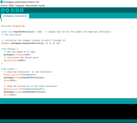
This time everything in the board was correct and as I wanted to use this board with the final project the next step was programming the board in order to move the motor. I used the same program than in output devices assignment with the new pin numbers this time the pin numbers 3,4,5 and 6.
In the following video you can see how the motor board worked well with the 12V regulator and the skectch. It was easy to do it but I had to check if the board could control a motor.
motor board test from msantisteban on Vimeo.
Code steper motor
	 #include <Stepper.h> //include Stepper.h library

const int stepsPerRevolution = 200;  // change this to fit the number of steps per revolution
// for your motor

// initialize the stepper library on pins 3 through 6:
Stepper myStepper(stepsPerRevolution, 3, 4, 5, 6);

void setup() {
  // set the speed at 60 rpm:
  myStepper.setSpeed(60);
  // initialize the serial port:
  Serial.begin(9600);
}

void loop() {
  // step one revolution  in one direction:
  Serial.println("clockwise");
  myStepper.step(stepsPerRevolution);
  delay(500);

  // step one revolution in the other direction:
  Serial.println("counterclockwise");
  myStepper.step(-stepsPerRevolution);
  delay(500);
}
Networking and communication
Master receiver - Slave writer
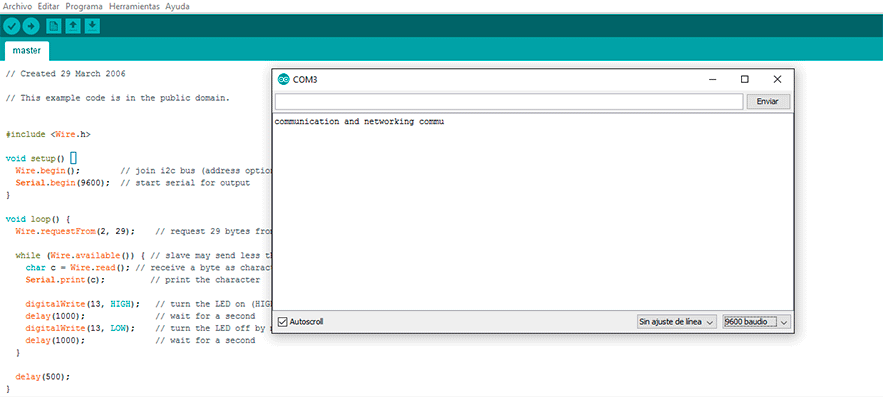
After programming the board and cheking that it worked with the stepper motor I programmed the communication between the boards with the I2C protocol. It was very easy because I used the wire library from Arduino so I only had to modify it adding the led and changing the response bytes to 29 for “communication and networking”
Code for the master Reader board
	// Wire Master Reader

#include <Wire.h> //include Wire.h library

void setup() {
  Wire.begin();        // join i2c bus (address optional for master)
  Serial.begin(9600);  // start serial for output
}

void loop() {


  Wire.requestFrom(2, 29);    // request 29 bytes from slave device #2 (SLAVE)

  while (Wire.available()) { // slave may send less than requested
    digitalWrite(13, HIGH);   // turn the LED on (HIGH is the voltage level)
    delay(1000);              // wait for a second
    digitalWrite(13, LOW);    // turn the LED off by making the voltage LOW
    delay(1000);              // wait for a second
    char c = Wire.read(); // receive a byte as character
    Serial.print(c);         // print the character


  }

  delay(500);
}
Code for the slave Sender board
// Wire Slave Sender

#include <Wire.h> //include Wire.h library

void setup() {
  Wire.begin(2);                // join i2c bus with address #2 (SLAVE)
  Wire.onRequest(requestEvent); // register event
}

void loop() {
  delay(100);
   digitalWrite(13, HIGH);   // turn the LED on (HIGH is the voltage level)
    delay(1000);              // wait for a second
    digitalWrite(13, LOW);    // turn the LED off by making the voltage LOW
    delay(1000);              // wait for a second
}

// function that executes whenever data is requested by master
// this function is registered as an event, see setup()
void requestEvent() {
  Wire.write("communication and networking "); // respond with message of 29 bytes
  // as expected by master


}
In the following video you can see how the slave board It's sending 29 bytes for “communication and networking” and the master is receiving it.
Master writer - Slave receiver
After programming the board and cheking that it worked with the stepper motor I programmed the communication between the boards with the I2C protocol. It was very easy because I used the wire library from Arduino so I only had to modify it adding the led and changing the response bytes to 29 for “communication and networking”
After checking the communication between the boards worked well with the master receiver and slave writer I decided to upload another sketch using the master as the writer and the slave as the reader because in my final project there is a communication between a master who gives orders and the slaves who receive those orders and transform them into actions (activating the motors).
I check the communication with the master writer and the slave receiver. I did a very simple arduino sketch: the master orders the slave to turn on it's led for five seconds and then turn it off.
Code for the Master Writer board
// Wire Master Writer


#include <Wire.h> //include Wire.h library

void setup() {
  Wire.begin(); // join i2c bus (address optional for master)
}

byte x = 0;

void loop() {
  Wire.beginTransmission(2); // transmit to device #8

  Wire.write(x);              // sends one byte
  Wire.endTransmission();    // stop transmitting

  x = 1;
  delay(5000);
   Wire.beginTransmission(2); // transmit to device #8

  Wire.write(x);              // sends one byte
  Wire.endTransmission();    // stop transmitting

  x = 0;
  delay(5000);
}
Code for the Slave Receiver board
// Wire Slave Receiver


#include <Wire.h> //include Wire.h library

void setup() {
  Wire.begin(2);                // join i2c bus with address #8
  Wire.onReceive(receiveEvent); // register event
  pinMode(13,OUTPUT);
}

void loop() {
  delay(100);
}

// function that executes whenever data is received from master
// this function is registered as an event, see setup()
void receiveEvent(int hola) {

  int x = Wire.read();    // receive byte as an inteSerial.println(x);         // print the integer

if (x==1)
digitalWrite(13,HIGH);

else
digitalWrite(13,LOW);
}
In the following video you can see how the master is sending orders to the slave to turn on the led and then turning it off.
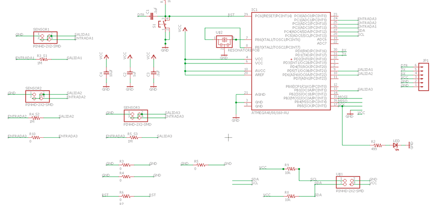
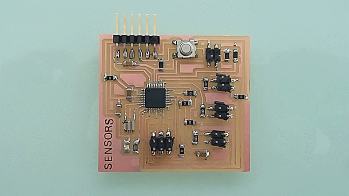
Designing the Sensors Board
As my final project has three different motor systems activated by three sensors I did a board in which I connected the sensors. I designed the board with Eagle and with the aid of the datasheet of the microcontroller I connected the sensors to it. The capacitive sensor needs two pins: one analog pin for the entrance and another digital pin for the exit.
I connected the sensors to the microcontroller to PC1, PC2 and PC3 for the entrance pins and PD5, PD6 and PB1 for the exit pins.
After milling the board I programmed it with my FabISP burning its bootloader with Arduino. As I didn’t have yet the H-bridges for my motor boards I decided to do the I2C connection between the sensor board and the motor boards only using the leds so I could advance with the programming of my boards.
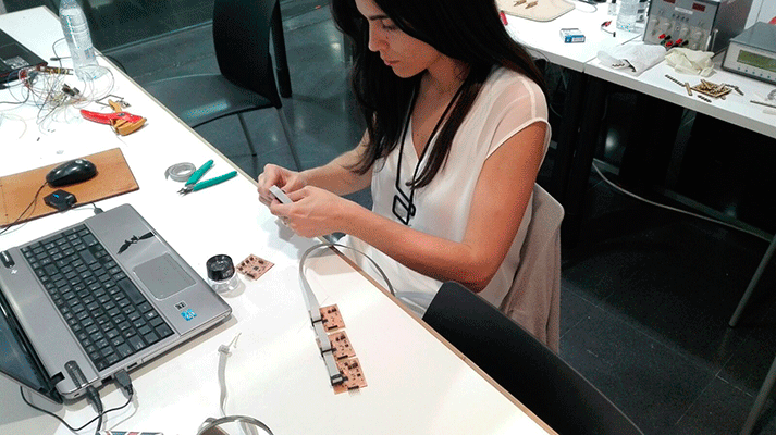
I did all the wiring between the 4 boards with a pain wire in order to establish a communication between them. When I finished doing the wiring I started programming the master board and the slave ones. I decided the sensor board to be the master board because this way the sensor board receives information from each sensor and it sends the information to the slave boards that will be the motor boards.
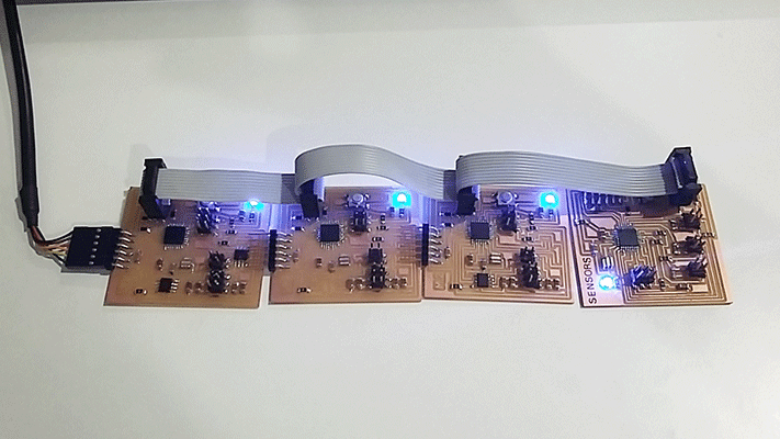
I started programming the four boards with each sketch. I did two different sketches: one for the sensor board that worked as de Master and another for the slave boards (the motor ones). I gave the same direction to the slave boards (wire begin(1)) because I only had one sensor. This way only one sensor was connected to the master board and when this received changes from the sensor, it sends to all the slaves to turn on its led so the four leds turned high.
MASTER BOARD
#include <CapacitiveSensor.h> // include capacitiveSensor.h library
#include <Wire.h> //include Wire.h library
CapacitiveSensor   cs_5_17 = CapacitiveSensor(5,17);
void setup() {
cs_5_17.set_CS_AutocaL_Millis(0xFFFFFFFF);     // turn off autocalibrate on channel 1 - just as an example


Serial.begin(9600);
Wire.begin(); // join i2c bus (address optional for master)
pinMode(13, OUTPUT);

}
byte x = 0;

void loop() {
  // read the sensor:
  long total1 =  cs_5_17.capacitiveSensor(30);

      if (total1 > 99){
        x = 1;
        digitalWrite(13,HIGH);
        Wire.beginTransmission(1); // transmit to device #1
        Wire.write(x);              // sends one byte
        Wire.endTransmission();    // stop transmitting
        Serial.println(x);
       }
     else{
       digitalWrite(13,LOW);
        x = 0;
        Wire.beginTransmission(1); // transmit to device #1
        Wire.write(x);              // sends one byte
        Wire.endTransmission();    // stop transmitting
        Serial.println(x);
       }


}
SLAVE BOARDS
// Wire Slave Receiver


#include <Wire.h>

void setup() {
  Wire.begin(1);                 // join i2c bus with address #1
  Wire.onReceive(receiveEvent);  // register event
  pinMode(13,OUTPUT);
}

void loop() {

}

// function that executes whenever data is received from master
// this function is registered as an event, see setup()
void receiveEvent(int hola) {
int x = Wire.read();    // receive byte as an inteSerial.println(x);         // print the integer

if (x==1){
digitalWrite(13,HIGH);
}
else{
digitalWrite(13,LOW);
}
}
In the video you can apreciate how the master board is receiving data from the sensor and sending it to the slave boards. The slave boards have the same skecth just to check if the master was able to read the data coming from the sensors and sending them to the slave boards.
sensor comunication 1 from msantisteban on Vimeo.
The next thing I did was to add two more sensors in the sketch and change the directions in the slave boards in order that each slave board illuminates just when the master board receive changes from the corresponding sensor.
In the following video the master and each slave has a different sketch in wich the master receive data from 3 differentsent sensors and sending them to each board. I only used one sensor but I changed the different connections just to show how it works.
sensor comunication 2 from msantisteban on Vimeo.
This time I fabricated two more sensors just to see the effect. The scketches are the same as the last video but you can see it better the workflow.
sensor connection 3 from msantisteban on Vimeo.
FILES:
Motor board
Sensors board
Master receiver - Slave writer
Master writer - Slave receiver
Sensor comunication1
Sensor comunication2