The aim for this week assignment is to manage cutting, engraving and soldering the different components in order
to do the final board of a programmer given by the Fab Lab. For this, it is indispensable knowing how the milling machine
(Modela) works and how the different mills necessary for this practice calibrate and adjust. Also, it is very important to distinguish
the different components used in the board, how they work and how they must be placed in our board.
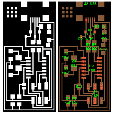
For doing this week assignment I’ve chosen FabISP in-circuit programmer.
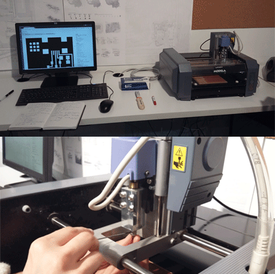
First of all, we have to consider that our milling machine works with Linux.
It was the first time that I worked with this operating system but I founded really similar to windows so
I didn’t had any problem with that. Secondly, we have to know that our machine doesn’t work with a pre-installed
program in our computer but it does through the internet: fablabmodules, program that allows us to handle the machine from our internet browser.
To be able to connect with this program it is necessary to open the terminal and write down ls to list all the programs and folders, and then write
./ fabmodules.sh to connect. We must leave the terminal open while we are running fabmodules.org.
And now, we will be connected to fabmodules.org. We have to be clear that we will be doing two different works:
first of it the engraving and secondly the final cut.

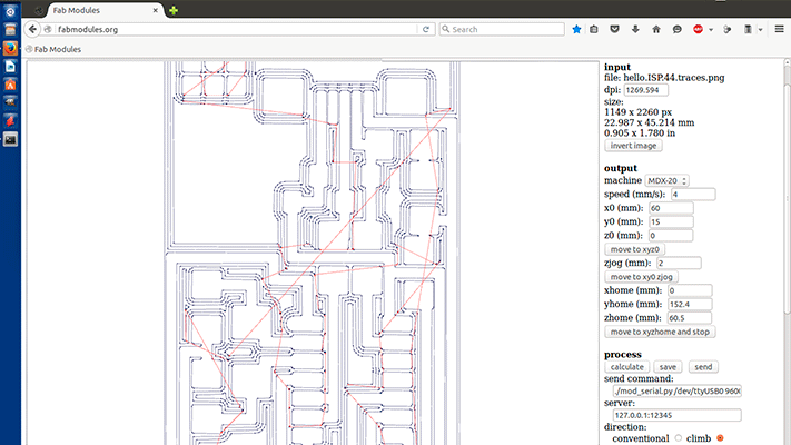
INPUT FORMAT: we select (image.png) in my case I’ll be doing the “hello.ISP.44” (interior) and the “hello.ISP.traces” (vias). As I had the .png files I selected image (.png)
OUTPUT FORMAT: there are the different types of milling machines and as we are working with the Rolando Modela, the output format will be Roland mill (.rml)
PROCESS: Here we select the mill that we will be using: for engraving we’ll be using the 1/64 mill (smaller and more fragile) and for cutting the 1/32 mill (bigger)
INPUT: we select the resolution of our image (dpi) In my case 1200 dpi
OUTPUT: We must choose the model of our machine, in this case MDX-20
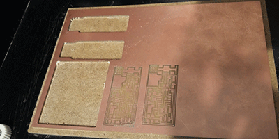
The values for X0,Y0, Z0 are for the point from which I want to start realizing my work, the position in the board. This is very important if I have more than one board that I want to cut in my PCB (FR1).
We must send the command by writing ./
When we select our machine, some parameters appear by default but there are some ones that we will probably have to change in order to have our board well done:
• Cut deph: this is the depth of copper that I want to remove from my PCB board (FR1) until I get to the Phenolic paper. It is possible that we have to change this parameter because the machine does not get good the 0.
• Tool diameter: we have to verify that if we are using one 1/64 drill corresponds to a value 4.
• Number of offsets: 4 by default. I will put -1 value if I want to take off all the copper in one and the machine will do X number of offsets till the black part in our image is away (the copper).
• Offset overlap: It is the percentage that overlaps in each offset the mill.
• Stock thickness: It is necessary to take into account at the moment of cutting a board of giving a bigger value than the thickness of our board to make sure that is well cut. It is important when cutting to put another board beneath our FR1 board in order to don’t break the base of our machine.
Once introduced all the parameters, what we have to do is to calibrate the mill at height Height Z0=0 and adjust the specific point where we want the machine to start. Then it is time to send the work to the machine.
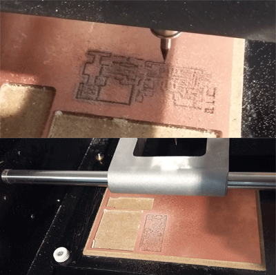
While engraving my board, the milling machine didn’t take off all the copper from one side of the board, this means that when I calibrate the height Z0=0 I did it from the center of my board (the highest part as it was curved) so there was a differ from heights between the height in the central part and the height of the external part so when the machine was engraving the external part didn’t remove all the copper .
It was my first experience with the assembly of components. I founded very delicate and difficult task because I didn’t imagine how little the components are! Although I practice a lot with some old boards that didn’t worked, I had some problems: first of all I didn’t took into account that each component had each own orientation in the board so I solder the ATTiny Microcontroller the other way so I had to desolder it and while doing it I broke up one via so I founded the fastest solution to re do another board.
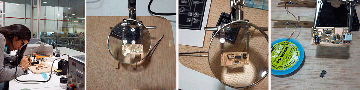
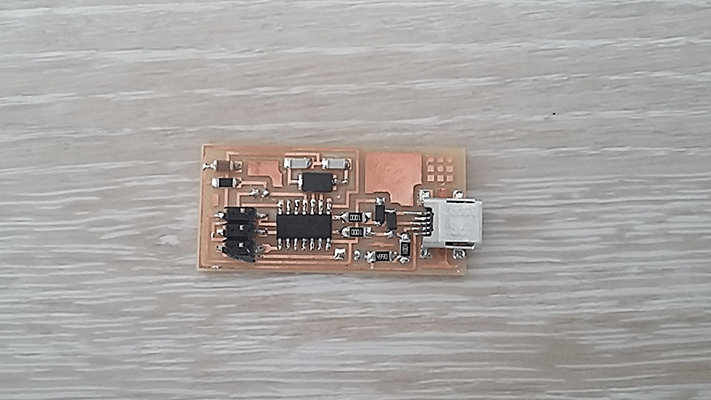
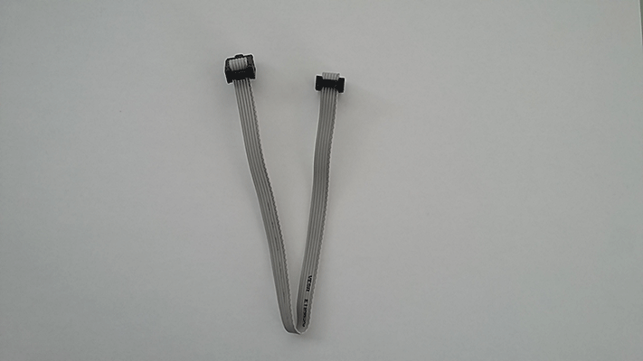
The next step was making the wire that connects the FabISP to other boards in order to program them.
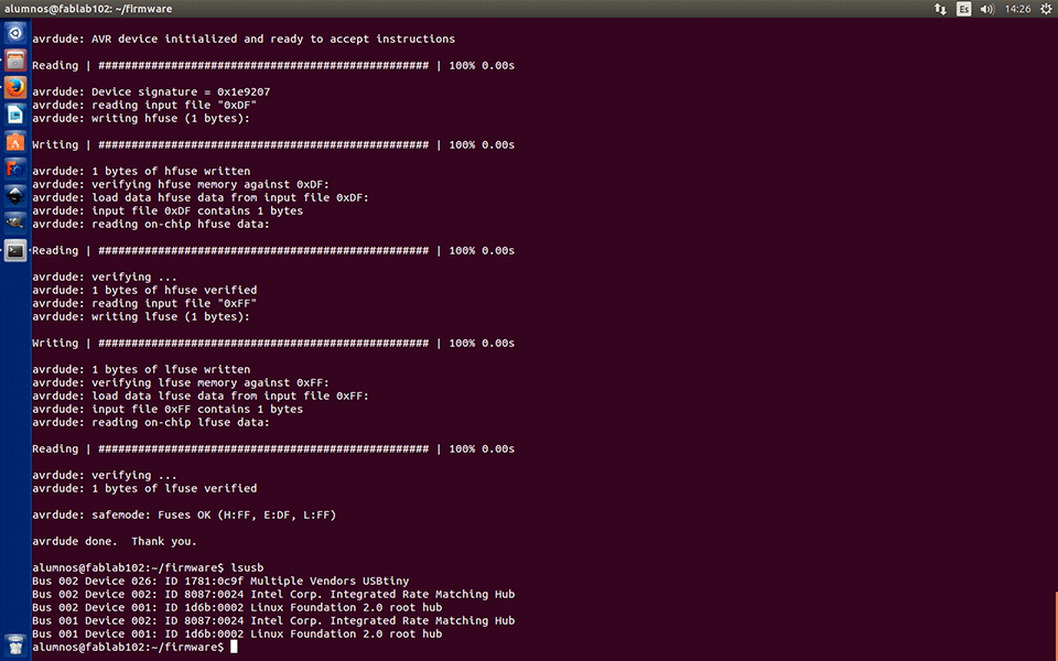
I followed the tutorial for programming my FabISP. For this, I used a computer with Ubuntu as the operating system. I opened the terminal and I started typing the different comands for the progammig. I typed "make clean" and the "make hex" and everything went good but when I typed "make fuse" and "make program" there was an error so what I did was cheking again if all the welding was good using the multimeter. There was a connection badly welded so I fixed it and this time I could do the programming.