
ADITYA BHATT

week-15 Networking and Communications
Assignment
Design and build a wired &/or wireless network connecting at least two processors
What is Networking?
Networking is social or professional interaction with people to exchange data or information.
Networking and Communications?
Networking is basically the communication between two microcontrollers, and thus transfer of data between them, we can control and co-ordinate. Here I have used my input device week with ultrasonic sensor I made the distance measuring mechanism and in output week I made a RGB LED. Here I am going to communicate with them. Before that i am going to learn some aspects about many serial communication whose interfaces compete for use in embedded systems. The right serial interface for your system depends on several key factors.
About the serial interface
There are many different reasons to use a serial interface. One of the most common is the need to interface with a PC, during development and in the field of electronic. Most, if not all PCs have some sort of serial bus interface available to connect peripherals. For embedded systems that must interface with a general-purpose computer, a serial interface is often easier to use than the ISA or PCI expansion bus.
I2C Interface
The Inter-Integrated Circuit bus (I2C) is a patented interface developed by Philips Semiconductors. (In order for an IC manufacturer to implement the I2C bus in hardware, they must obtain licensing from Philips.)
The I2C bus is a half-duplex, synchronous, multi-master bus requiring only two signal wires: data (SDA) and clock (SCL). These lines are pulled high via pull-up resistors and controlled by the hardware via open-drain drivers, giving a wired-AND interface.
I2C uses an addressable communications protocol that allows the master to communicate with individual slaves using a 7-bit or 10-bit address. Each device has an address that is assigned by Philips to the manufacturer of the device. In addition, several special addresses exist, including a “general call” address (which addresses every device on the bus) and a high-speed initiation address.
SPI
The Serial Peripheral Interface (SPI) is a synchronous serial bus developed by Motorola and present on many of their microcontrollers.
The SPI bus consists of four signals: master out slave in (MOSI), master in slave out (MISO), serial clock (SCK), and active-low slave select (LSS). As a multi-master/slave protocol, communications between the master and selected slave use the unidirectional MISO and MOSI lines, to achieve data rates over 1Mbps in full duplex mode. The data is clocked simultaneously into the slave and master based on SCK pulses the master supplies. The SPI protocol allows for four different clocking types, based on the polarity and phase of the SCK signal. It is important to ensure that these are compatible between master and slave.
Netwoking with Ultrasonic sensor with RGB
I am planning to connect my input and output week that is based on the reading of the ultrasonic sensor with which I am going to change the color combination of the RGB.
I am first planing to program the ultrasonic sensor attached to the board.
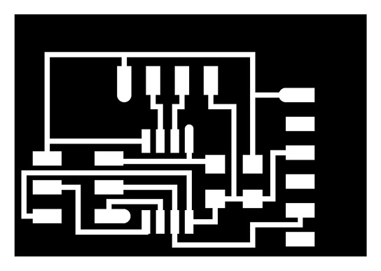
For the programming I refered the following diagram
.jpg)
After that I reffered the schematic of the circuit.
.jpg)
The board file is here

The picture of the board is given below
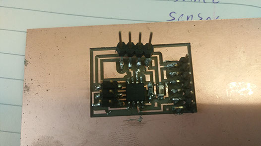
I have used arduino for programing the board
#include <NewPing.h>
#include <SoftwareSerial.h>
#define RxD 1
#define TxD 2
#define DEBUG_ENABLED 1
int Range = 0;
SoftwareSerial sserial(RxD,TxD);
NewPing sonar(0,1,30); //NewPing sonar(TRIGGER_PIN, ECHO_PIN, MAX_DISTANCE);
void setup()
{
sserial.begin(9600);
}
void loop()
{
// Range = sonar.ping();
sserial.write(Range);
sserial.write('#');
}
Programing the RGB led output device board
Pins and components connections
.jpg)
The traces of the board are given below
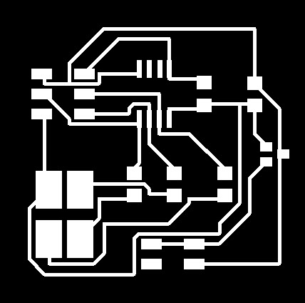
.jpg)
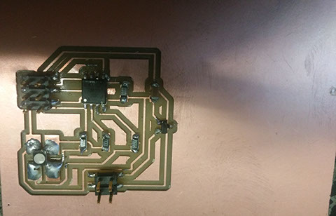
The picture of the ready RGB output device is given below
Programing the board
#define redPin 1
#define greenPin 2
#define bluePin 0
#define RxD 1
#define TxD 2
#define COMMON_ANODE
#include <SoftwareSerial.h>
SoftwareSerial sserial(RxD,TxD);
void setup()
{pinMode(redPin, OUTPUT);
pinMode(greenPin, OUTPUT);
pinMode(bluePin, OUTPUT);
sserial.begin(9600);
}
char c;
int range = 0;
int t;
void loop()
{
c = sserial.read();
if (c == '#')
{
range = 0;
}
else
{
t = c;
if (t > 47 && t < 58)
{
t = t - 48;
range = range * 10 + t;
}
}
if (range<10)
{
setColor(range*25, 0, 0);
}
else
{
if (range<20)
{
setColor(255, range*25, 0);
}
else
{
setColor(255, 255, range*25);
}
}
}
void setColor(int red, int green, int blue)
{
#ifdef COMMON_ANODE
red = 255 - red;
green = 255 - green;
blue = 255 - blue;
#endif
analogWrite(redPin, red);
analogWrite(greenPin, green);
analogWrite(bluePin, blue);
}
All parts and working of the board-
The first part is meant for the board that interfaces with the ultrasonic sensor. It is quite simple, just initializes the ultrasonic sensor, takes the reading from it and send it via a soft-serial output. Between each reading, a ‘#’ is inserted to identify the end of one reading and the beginning of the next.
The second part of the program is meant for the LED board. This accepts the serial data from the other board. The data is recived character by character. If ‘#’ is found, the values are reset. If a sequence of decimal is found, it’s converted to a number. This number, if less than 10 the RED led in the RGB led is lit up with the appropriate brightness. If more than 10 and less than 20, RED is lit with full brightness and GREEN with the brightness corresponding to the distance, similarly for the distance between 20 and 30. For more than 30 all are lit with full brightness.
Final output and working