At the beginning of the course I proposed to develop solar tracking device/cooker.
I’ve been spinning around my subject in spiral rollercoaster which took me very fast from week to week until here and now.
The journey was full of surprises and challenges.
Each week I tried to take a bite that I could deal with, and also took some risks.
I finished up with working (scaled 1:4) motorized and tracking light prototype and with full scale prototype of parabolic mirror. The prototype has its parametric tools for personal fabrication.
I can see some potential future for the project development, like: to add temperature sensor; to make it portable; to create press fit kit from it.
I believe I became better designer after FabAcademy and I know now for sure that if you want mo make a machine or to build almost anything - you should do it in team.
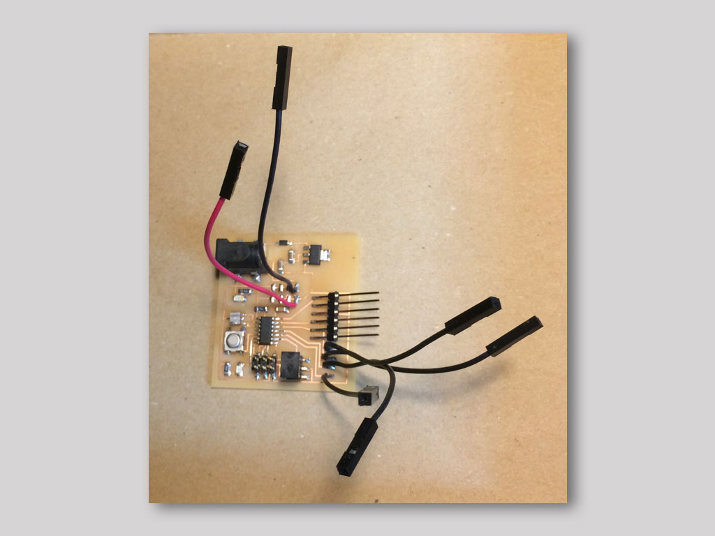
Welcome to visit the final project Concept Page to see more about the idea and sketches Here is the final project Process Page which contains all the project development stages and links to the weeks that I managed to deticate to my final project. More about the solar tracking/cooking subject and ideas can be found on my Applications and Implications week page. I created sun tracking cooking device which measures light data from four LDR photo resistors and according to that data device fixes the position of the parabolic mirror using two servo motors. Each motor rotates different axis. X axis rotates left and right and Y axis tilts up and down.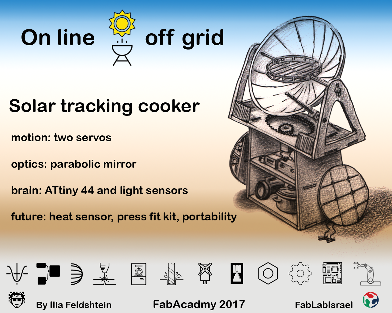
My project has:
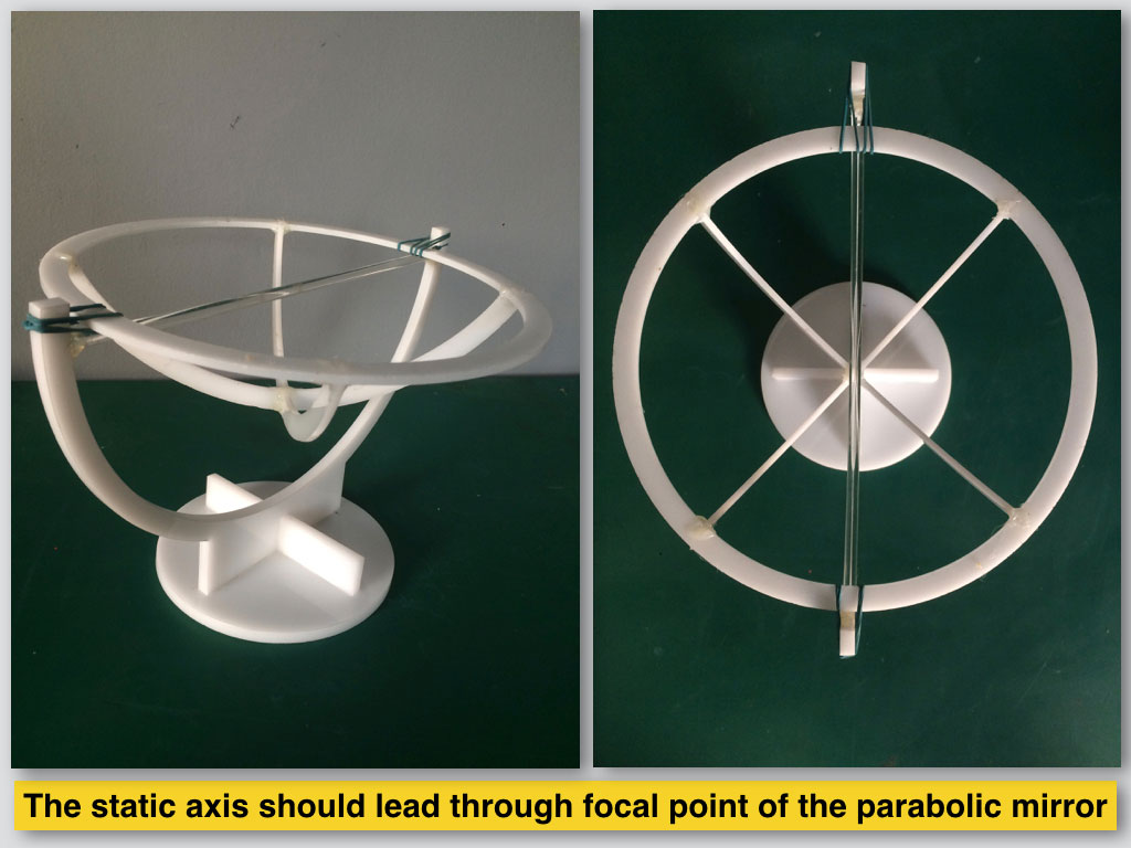
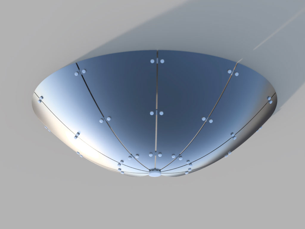
Structure - press fit kit (for now 1:4 scale) for laser cut miniature. It contains 2D and 3D files of parabolic mirror and its support structure. Used cardboard for the dish. There is also file for the base structure. Used perspex, option - plywood. Motion - two 5V servos. One Lazy Susan bearing at the X base axis and two around axis Y shaft. Optics - parabolic mirror fabricated with FabLab tools only. I’m proud to tell that not the 1:1 scale mirror I created is important but the personal parametric fabrication process for small machines that has been created on the way is.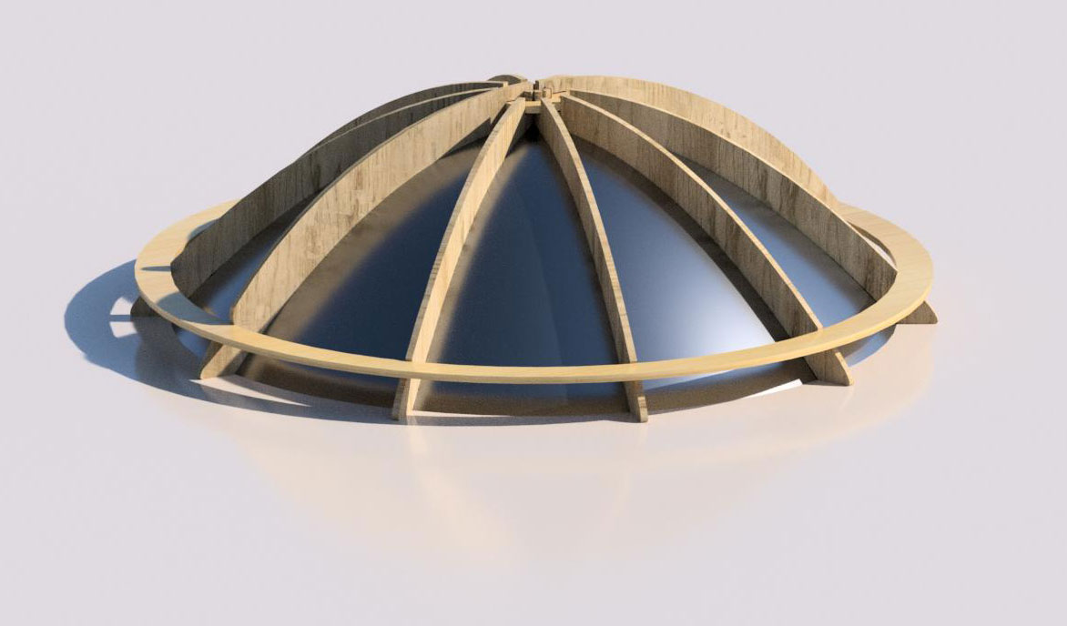
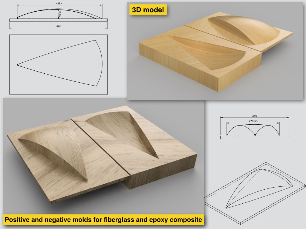
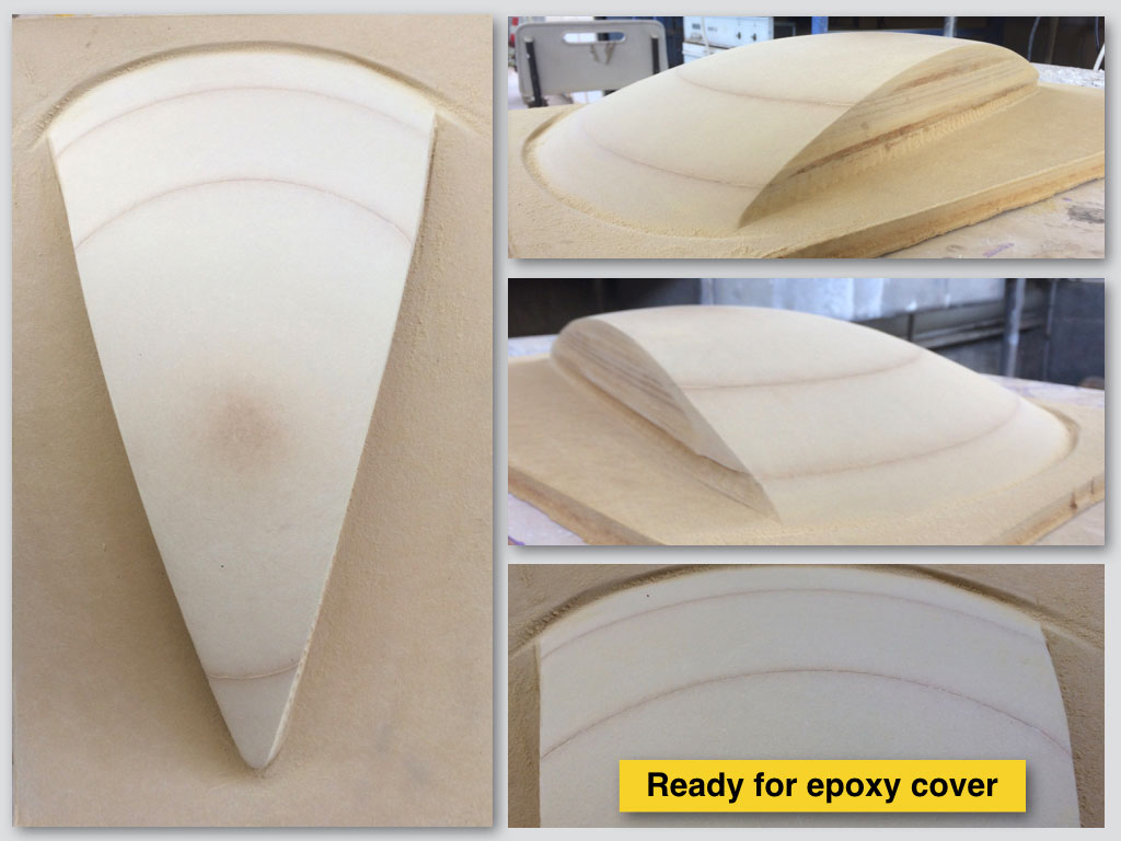
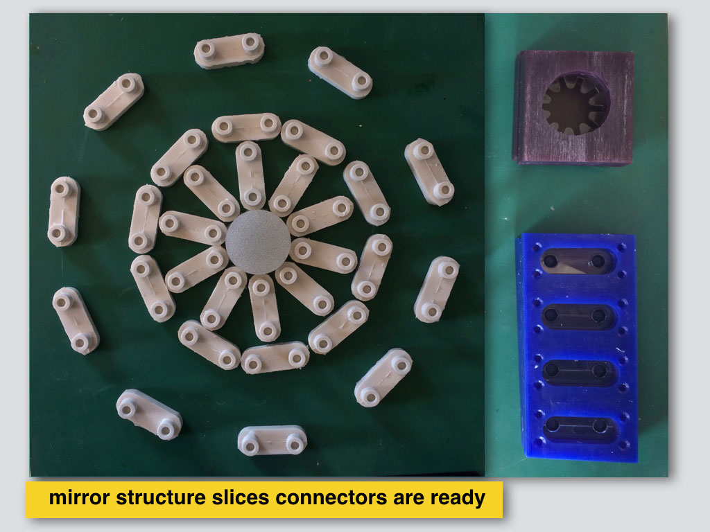
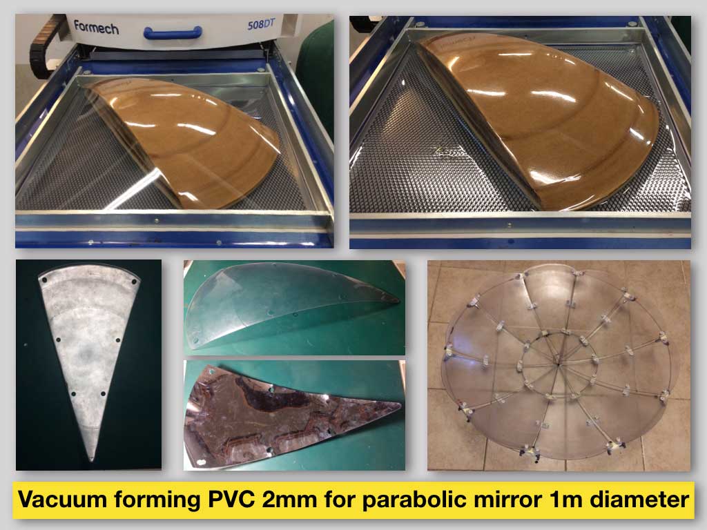
I have made with CNC machine MDF positive mould for 1/10 peaces of mirror. On that mould I’ve made successful composites test and later used it to vacuum form 10 sheets of 500*500cm PVS 2mm thickness. All the peaces connected together and covered with mylar gave me 1000mm diameter 250mm depth parabolic mirror. For the mirror slices connection I created another two CNC machined negative moulds from wax blocks and casted multiple silicone connectors in them. I used Vinyl cutter to cut the reflective mylar cover for each slice of mirror separately.
BOM
Around 170$:
Electronics and wiring: 10$PVC vacuum forming: 30$
Mylar film: 10$
Silicone: 10$
Plywood for structure: 50$
Metal grill and rod: 20$
Bearings 10$
Motors: 30$