Week 8 - Embedded programming
- Program your board to do something, with as many different programming languages and programming environments as possible
- Extra credit: experiment with other architectures
- Echo hello board made on week 6
- Arduino Micro ISP
- FTDI cable
- Oscilloscope
Softwares :
- Arduino IDE A software to write code and upload it to a board.
This week was a huge dive in the microcontroller world which is full of possibilities. I read the microcontroller datasheet and took a few weeks of experimentation and reading to get some kind of understanding that I summarized here below. I tested the use of the PWM output pin of the microcontroller to make a led to blink with a varying intensity (sinusoidally). I then used the serial transmission to make the board do something and also read something from it. I've sent an ascii character and read the corresponding numerical value through the serial line. Along the way, I found that my echo hello-world board had some problems that I solved back on week 6.
reading a microcontroller datasheet
I started by opening this data sheet of the 8-bit AVR Microcontroller with 2K/4K/8K Bytes In-System Programmable Flash (ATtiny24A, ATtiny44A, ATtiny84A) which is 286 pages long.
Pin descriptions
The first thing I looked at is at the pin descriptions that depends on the microcontroller we have, here it is the ATtiny84 microcontroller. All the pins can have different functions that can be found at the beginning of the datasheet. A critical limitation of the microcontroller is the number of pins and the functions they allow. the most important ones are
- the VCC and GND pins that allows to power the microcontroller in 5V DC.
- the MISO, MOSI, SCK, RESET pins that allows to program the microcontroller using the SPI data protocol.
- SCL and SDA pins allows to communicate with the microcontroller using the I2C data protocol.
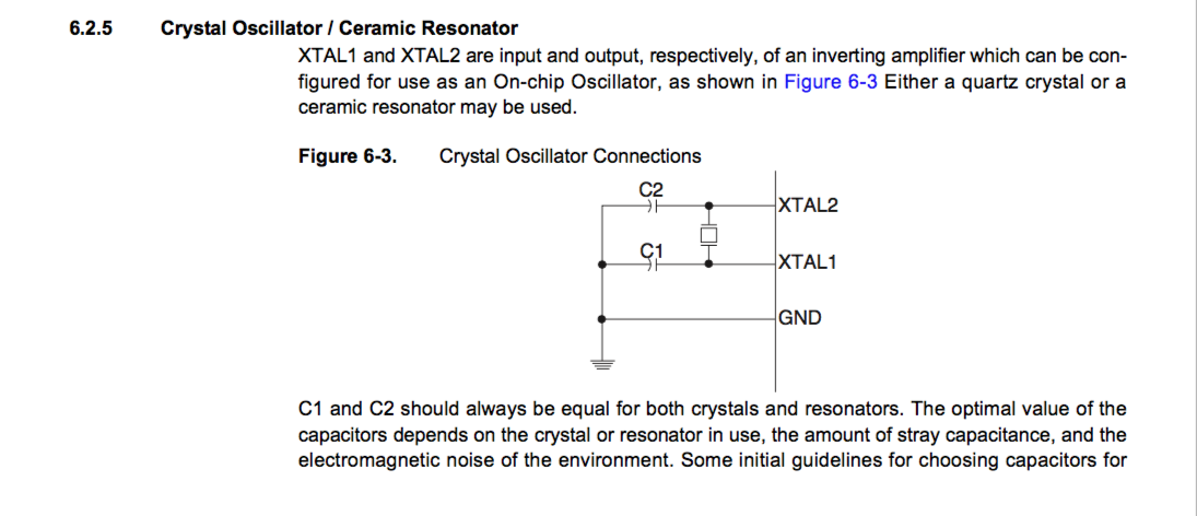
- XTAL1, XTAL2 allows to use an external clock and more precise clock then the built-in clock in the microcontroller.
- PCINT pins that allows to interrupt the running microcontroller and command it for a specific task that we can program.
- 8 ADC (Analog to Digital Converter) pins allows to digitalize an analog signal using the 10 bits microcontroller ADC detailed on page 132 of the datasheet.
- PWM (Pulse Width Modulation) pins allows to generate an analog signal with a pulsed digital signal (high and low state).
I found this unofficial pinout diagram pretty useful to have an overview of what each pins does.
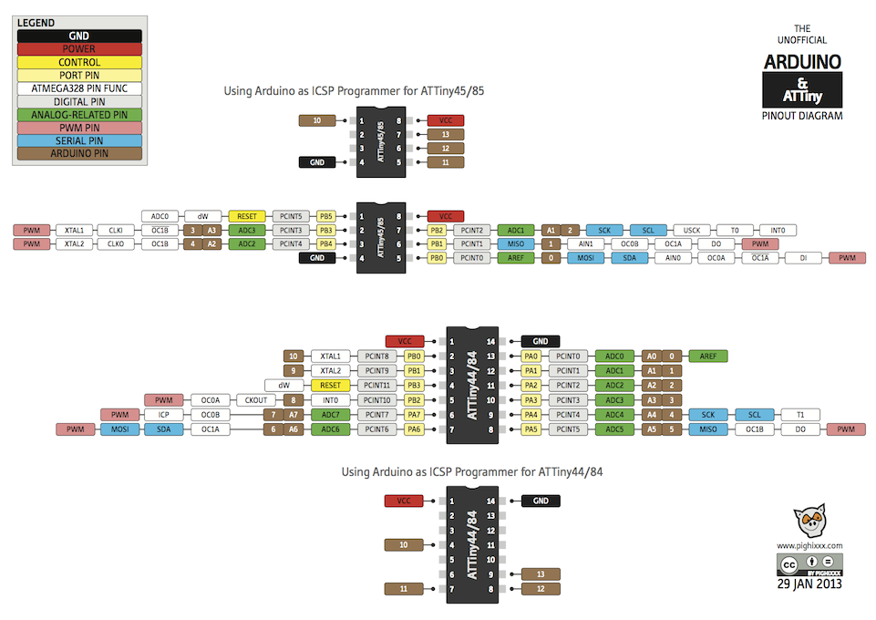
If more information is required, we can dig into the microcontroller datasheet. For example, the ADC (Analog to Digital Converter) is detailed on page 132. The way we should add the external clock on the board is explained on page 28.
Block diagram
It is interesting to dig further into the microcontroller and learn more about this complete ecosystem. It is impressive how many possibilities are hidden into this millimetric microchip. Looking into the block diagram, we learn about the chip's AVR enhanced RISC architecture.

Memory
In the ATtiny84 microcontroller, I've learned that there are 6 types of memory:
- 32 registers which are really fast to read and write data (general purpose)
- 512 Bytes of RAM (Random-Access Memory) is flash memory used to save data and program instructions that are used frequently,
- 512 Bytes of EEPROM which is read only non-volatile memory for data too (memory values are kept when the board is turned off),
- 8KB of In-System Programmable Flash memory which is used to store the microcontroller program,
- the fuse is where the microcontroller is configured.
CPU speed
The ATtiny can perform about 1 MIPS (Millions of instructions per second) per MHz which means that for internal or external clock of 20 MHz, it can perform about 20 MIPS.
What about the Arduino ?
Arduino's are often really well known and used in the maker community. But what about them ?
An Arduino is made of 5 different things:
- It is a board with a microcontroller and different input and output pins that allows to connect different peripherals, sensors and actuators;
- with a bootloader, the microcontroller is already programmed to allow the reception of new programs;
- it has C libraries that can be used to program the board and manipulating data. It eases the programing but libraries can be quite heavy in memory and computing power;
- IDE Integrated Development Environment is a software application that allow to write, compile and upload a program to the Arduino;
- a header.
Questions that I have.
Diving into the world of microcontrollers can feel overwhelming as it opens enormous possibilities. So keep moving and learning bit by bit seems a good option. If I think about some questions that I have at the moment, here are they: What are the limits and the possibilities of these little microcontrollers ? For what kind of applications are they useful ? Are they reliable for scientific data acquisition ?
Testing the board and uploading a program on the microcontroller
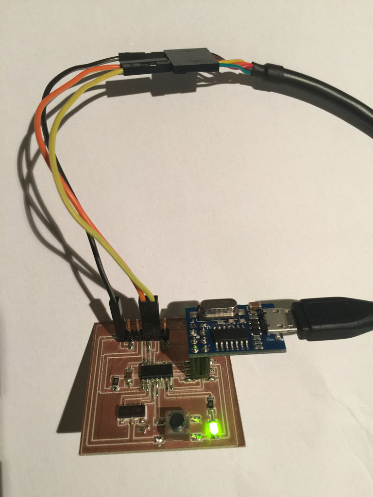
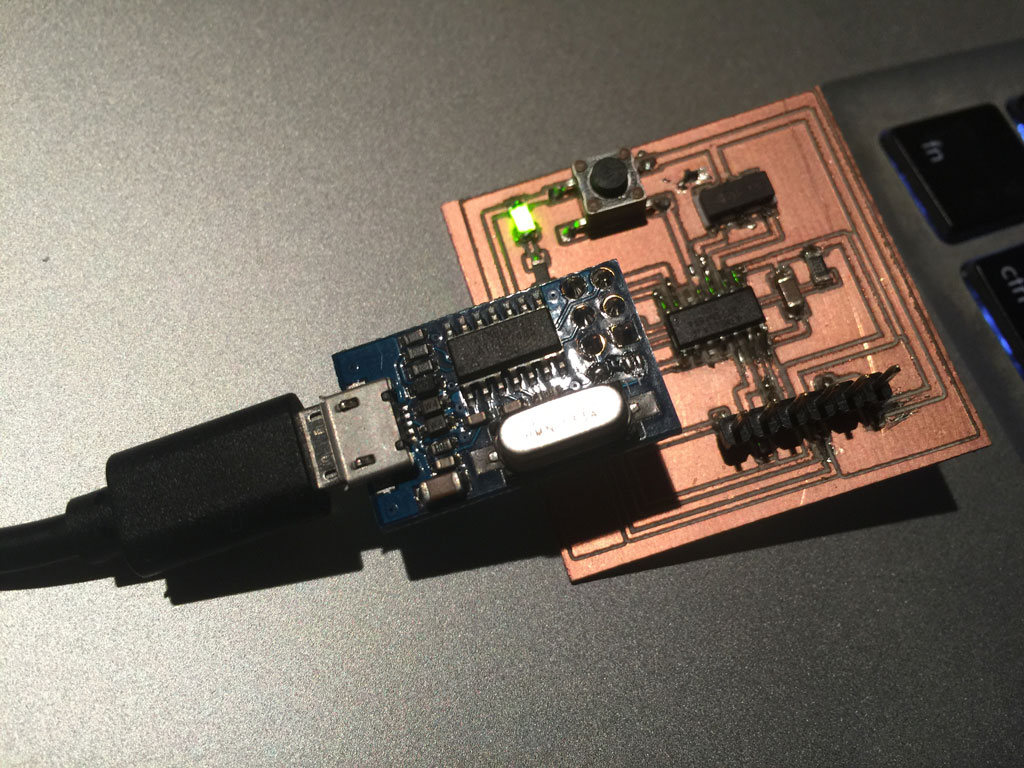
To program the board I made on week 6, I used an Arduino micro ISP to upload a program on the microcontroller.
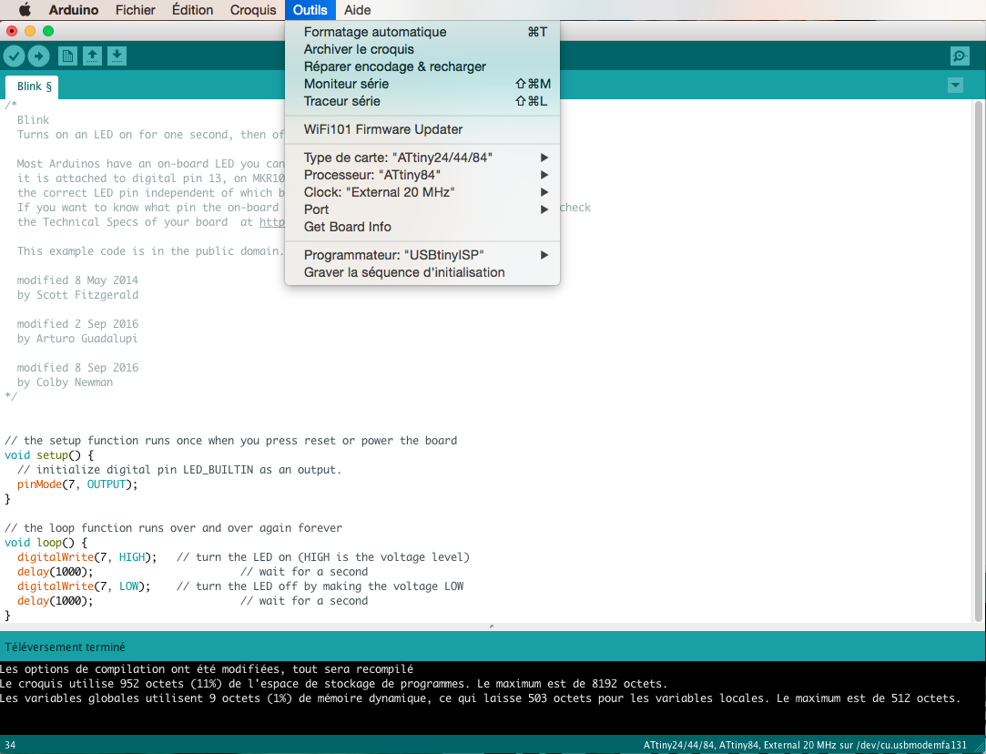
To do that, I used the Arduino IDE. I opened the simple "blink" program to test the microcontroller. In the program, I just changed the led pin number to 7. In Arduino's world pin 7 corresponds to the pin number 6 of the microcontroller (see above pinout diagram) on which the led is wired on my board.
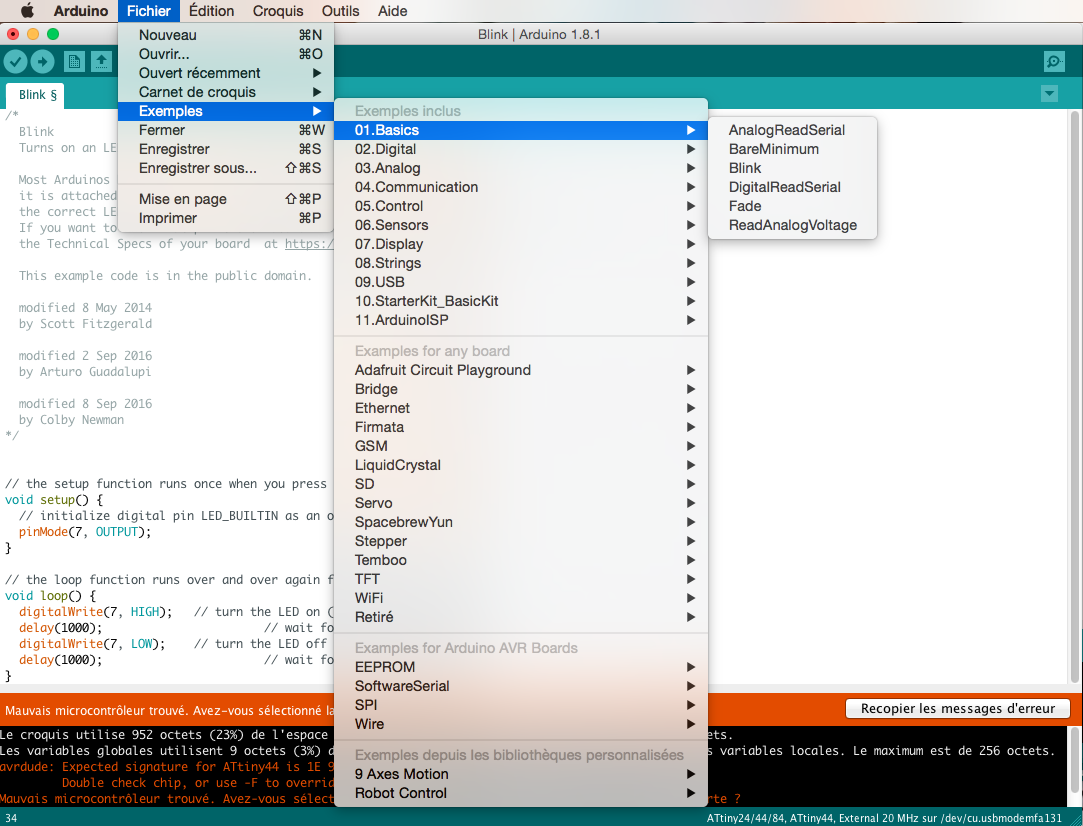
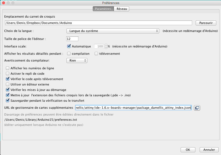
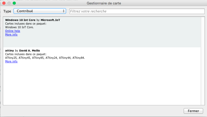
To connect my ATtiny, I had to upload additional board manager in the Arduino IDE. I have followed this tutorial.
Then I set the microcontroller parameters in the tool tab and uploaded the program.
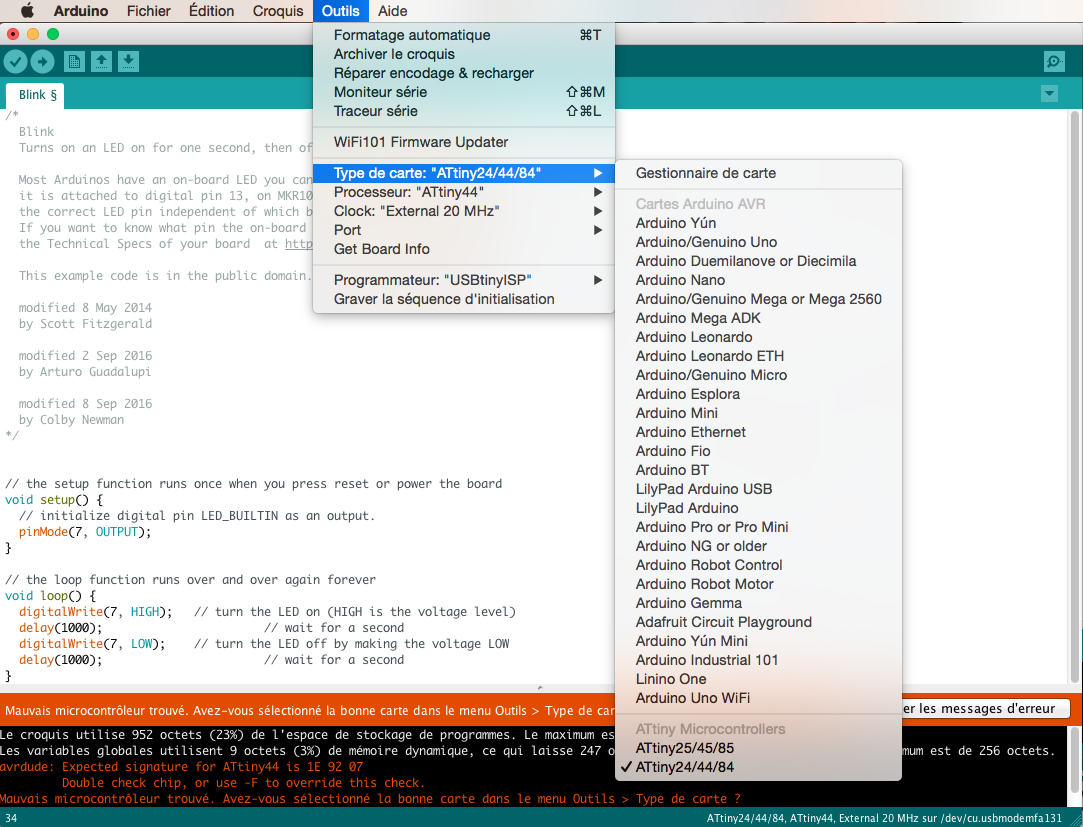
Problem !! I used the wrong microcontroller on my board... The ATtiny44 I soldered has an external clock limited to 16MHz and I am using a 20Mhz. We thus had to change the microcontroller and use a ATtiny84 instead. Let's unsolder the ATtiny44 and solder back the ATtiny84.
The led is blinking, it is working !!!
Ok, now everything seems to work properly.
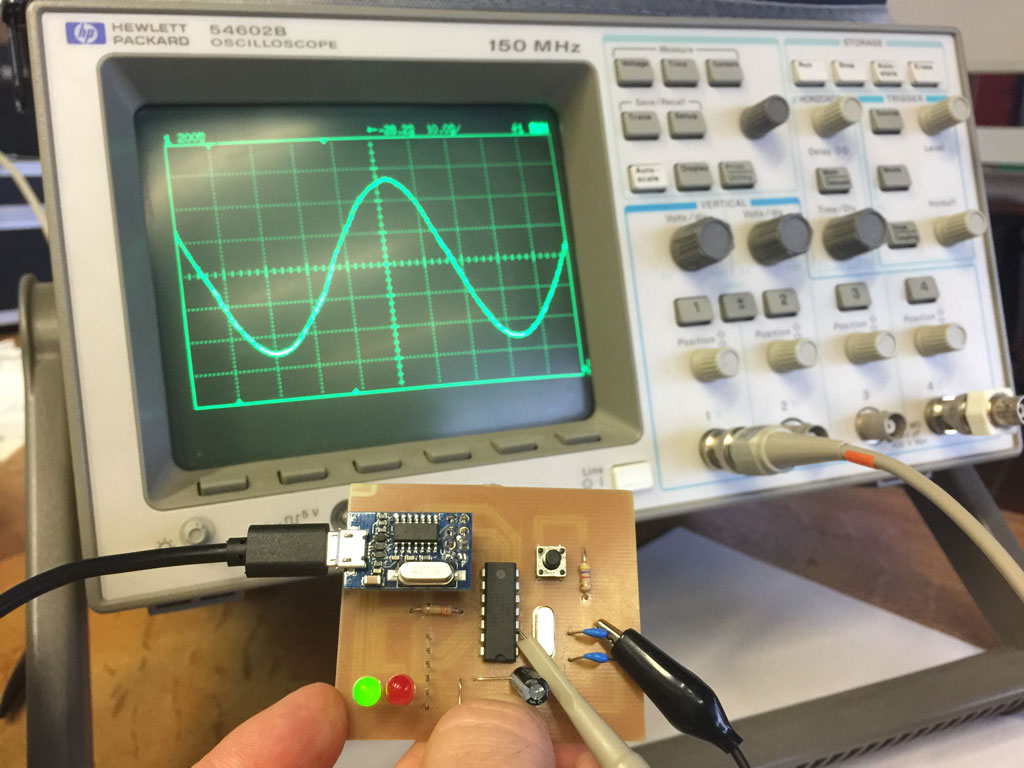
Debugging David's board
David had a problem with the external clock of its board. We debugged it using an oscilloscope. Here we can see the oscillation of the 16MHz crystal.
Using PWM with the led
Sinusoidal blinking of the led
I wanted to learn more about PWM. Thus I followed this PWM tutorial and I made this code to make the led to blink at different intensities (sinusoidally).
Code to make the led to blink sinusoidally
Serial communication
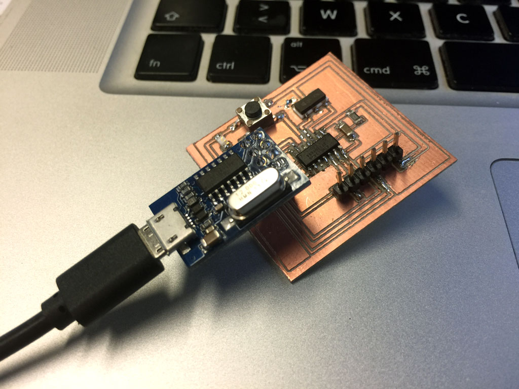
I then explored the world of serial communication following this Serial communication tutorial. I used an FTDI cable and I found that something was wrong with the board. In fact there was a problem with the reset pin of the FTDI cable that I corrected here on week 6.