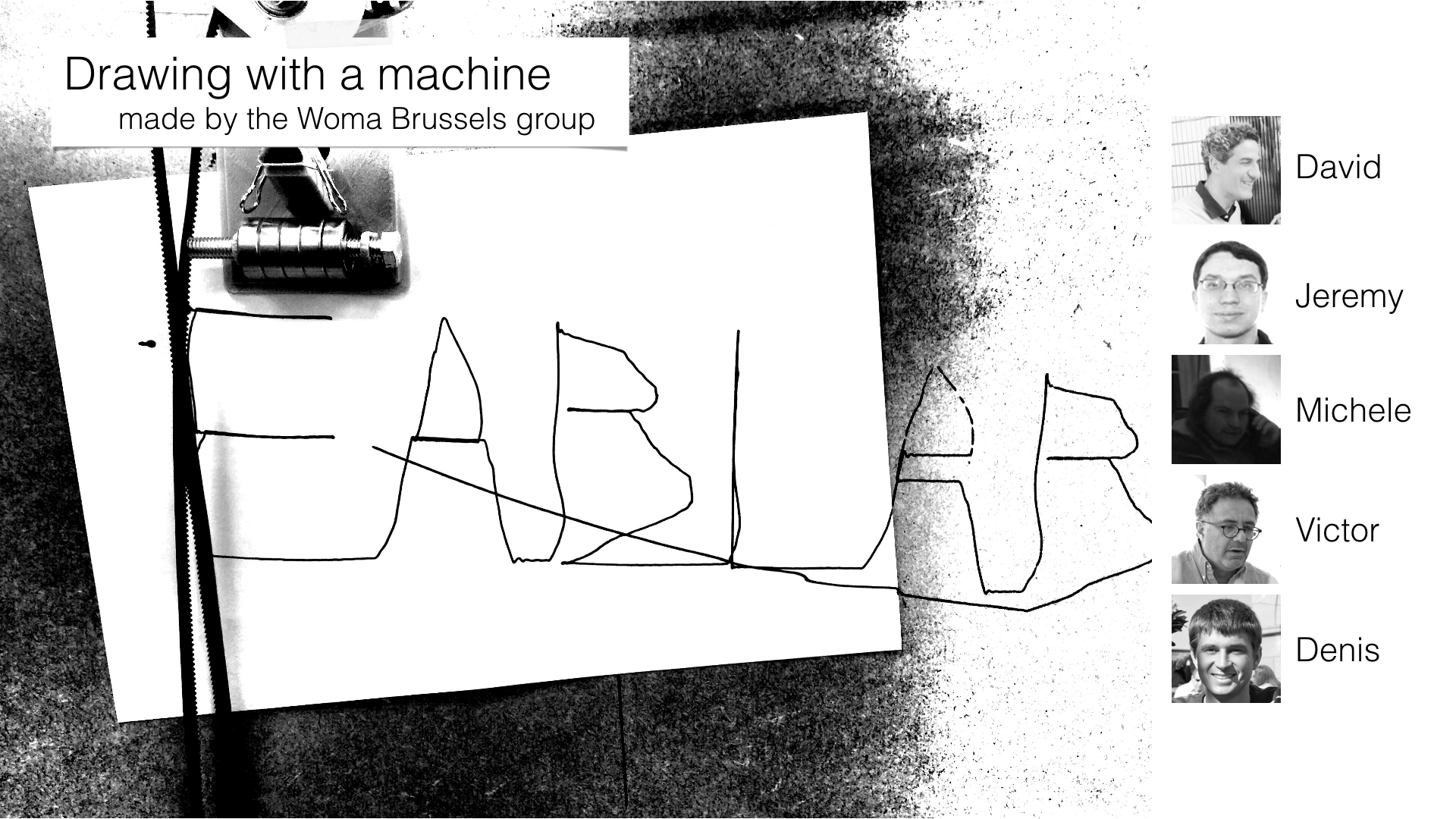
Woma Brussels Group project
Source files for this week.
Presentation video of the making of our drawing machine
Preamble
This group project is going to be a real challenge. We are in the middle of the semester and everybody is a bit tired because of the Fabacademy, the classes we are teaching in our own university and projects in our parallel professional life. We met all together on Friday afternoon and brainstormed about what machine we could make. After the brainstorm, we wanted to make an origami (pre-)folding machine. The very difficult part is that we have asynchronous agenda and it is difficult to have long period of time where we are all together. So we decided as a start to divide the work into parts and assigned them to each of us.
| Who ? | What ? |
|---|---|
| Victor | Research on the end effector to pre-fold origami. |
| David | prepare the 2D/3D files to be cut. |
| Jeremy | get the materials and laser cut the stages. |
| Michele | build the linear stage. |
| Denis | In charge of the documentation and the team and tasks organization. |
A machine to make origami
Sketches
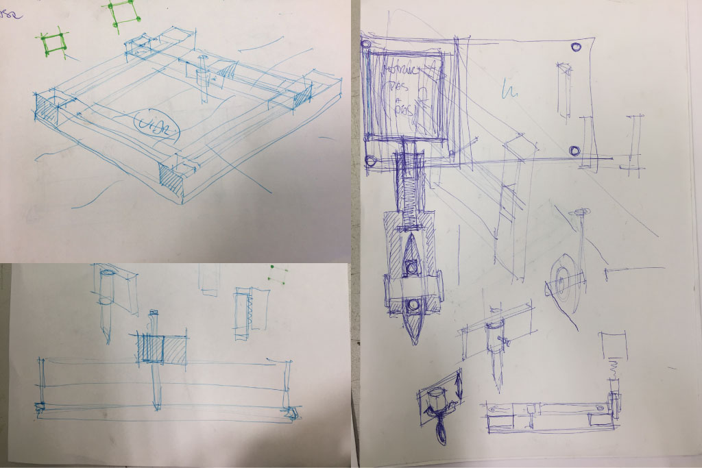
As a start Victor made some sketch of the machine we could make.
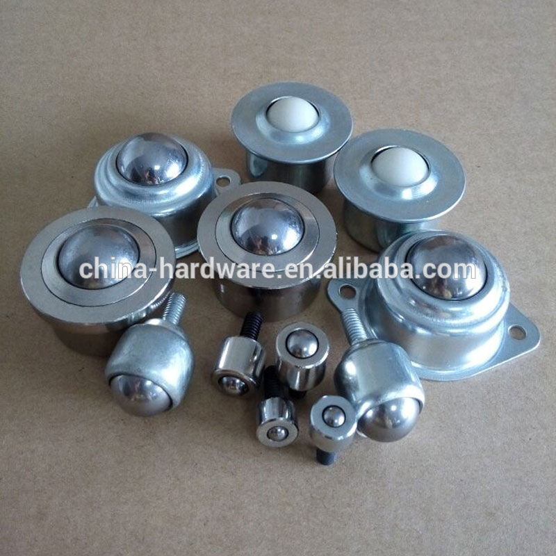
The end effector
Victor also looked into the different end effectors that could be used to pre-fold cardboard and paper.
Building the linear stages - 1st attempt
Preparing the 2D digital files
David downloaded the files from the cardboard stages tutorial page. But there was a problem in the file which link to the parametric file was broken. That's what led to our first failed attempt. It seemed that the thickness was set by default on 3 mm.Cutting
To build the linear stages, Jeremy cut plain cardboard that we had in the lab.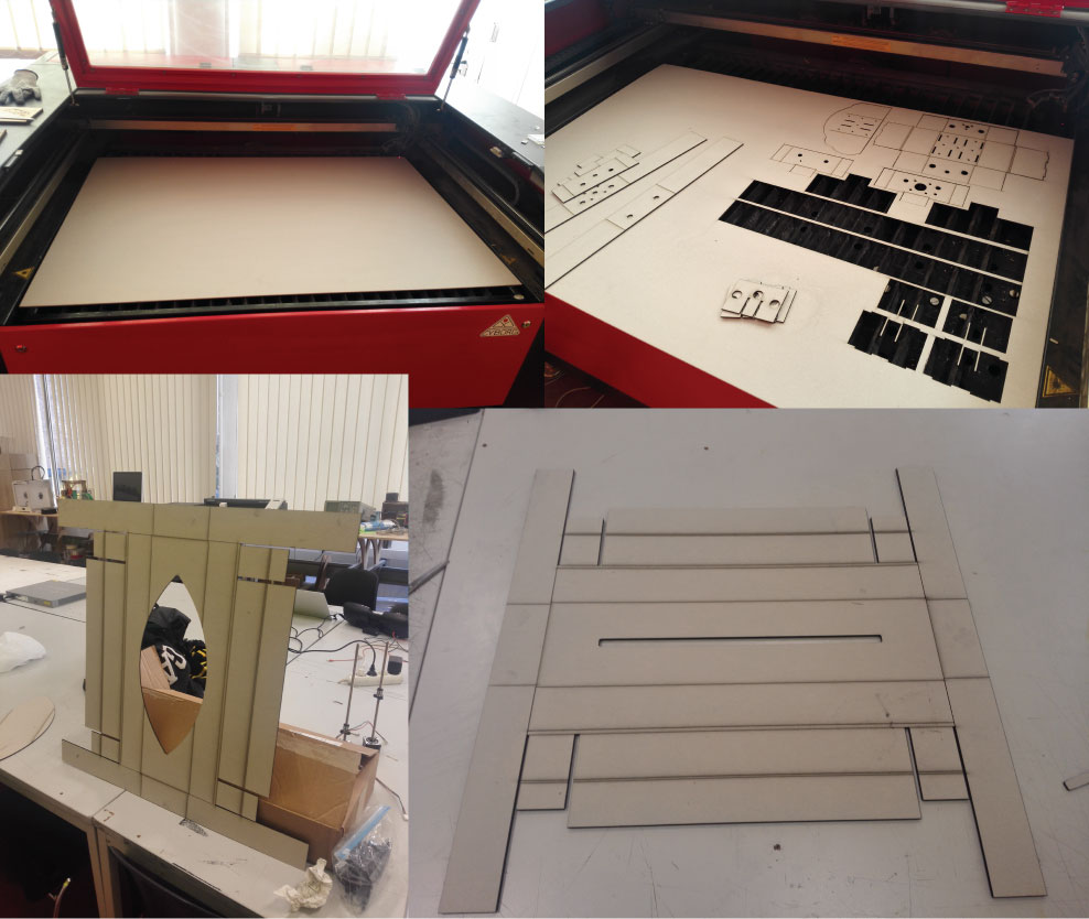
Assembling
This cardboard has the good thickness (3 mm) but we had a lot of difficulty to fold it.
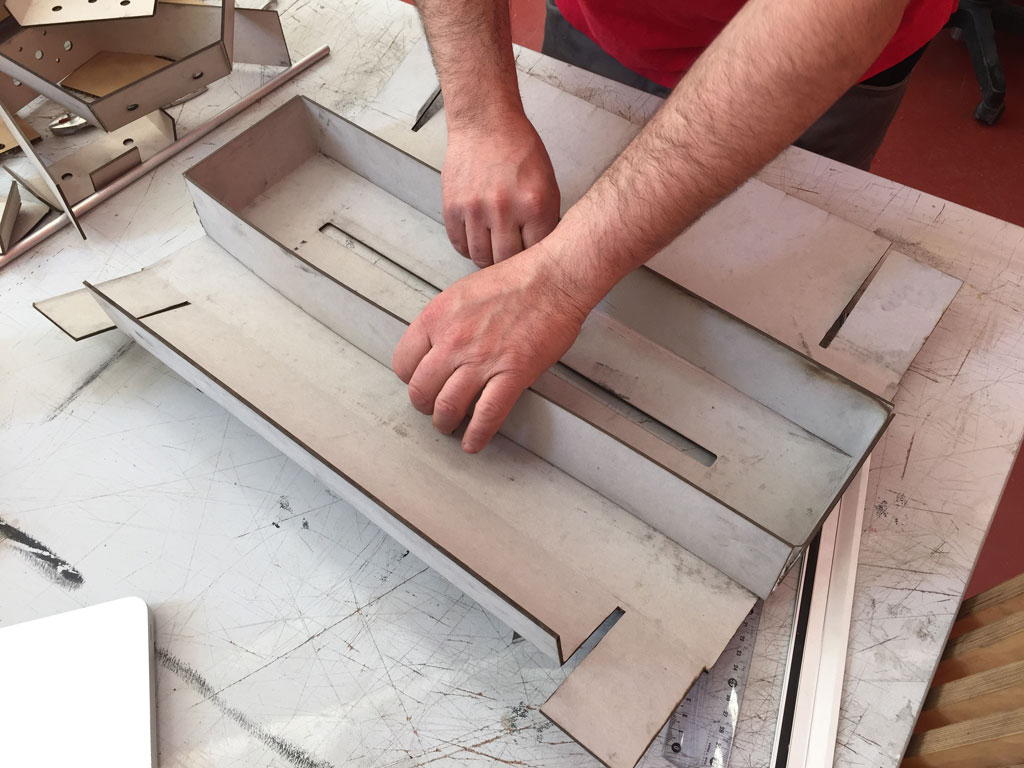
Victor and Jeremy then used another cardboard that was easier to fold but too thick for the linear stage design (we couldn't change the thickness parameter easily has the parametric file was borken).
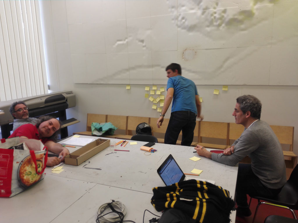
Team organisation
Energy, feed and loss
A group is like a living organism. Energy is entering in the group and energy is dissipated/lost out of the group. When input energy is higher than output energy, the group is healthy. But when output energy becomes a bit too high it's good to stop and reflect on it. That's what we did on Tuesday morning. We used post-its too identify "good" energies and "bad" energies. It was really interesting has everybody could express himself, we got to know each other a little bit more and debated on ways to improve the way we work together.
Here is what came up after this meeting:
- we have asynchronous agenda
- we have a parallel professional life
- There is a willing to work in flexible and small groups
- There are some difficulties between the organized and the less organized personalities. Organized profiles are good to structure, plan and are very efficient at achieving some tasks. The less organized profile are very good at creating surprise, coming up with new ideas and are very very efficient on some task also (but not the same as the other profile).
- We have complementarities in the team member profiles
- We have different ways of working
- There is a willing in the group to back up and help each other when needed.
- We will divide and organize the work in small parts on which we can work in small teams.
Building the linear stages - 2nd attempt
On Tuesday afternoon, Victor and Denis cut and assembled two linear stages with a 3mm cardboard. Michele came to help the team also.
Cutting
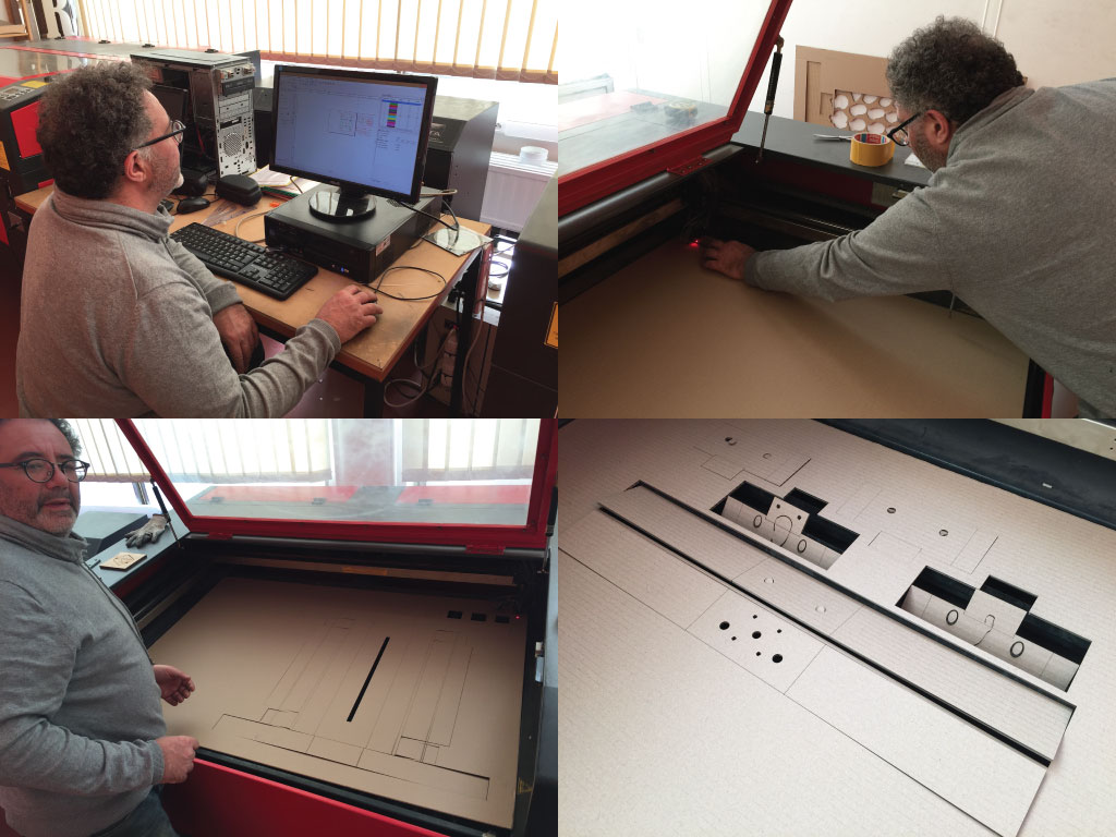
Assembling
The kit was quite easy to assemble.
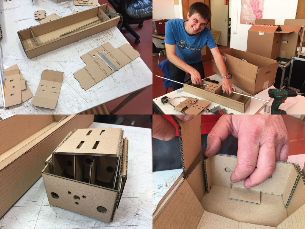
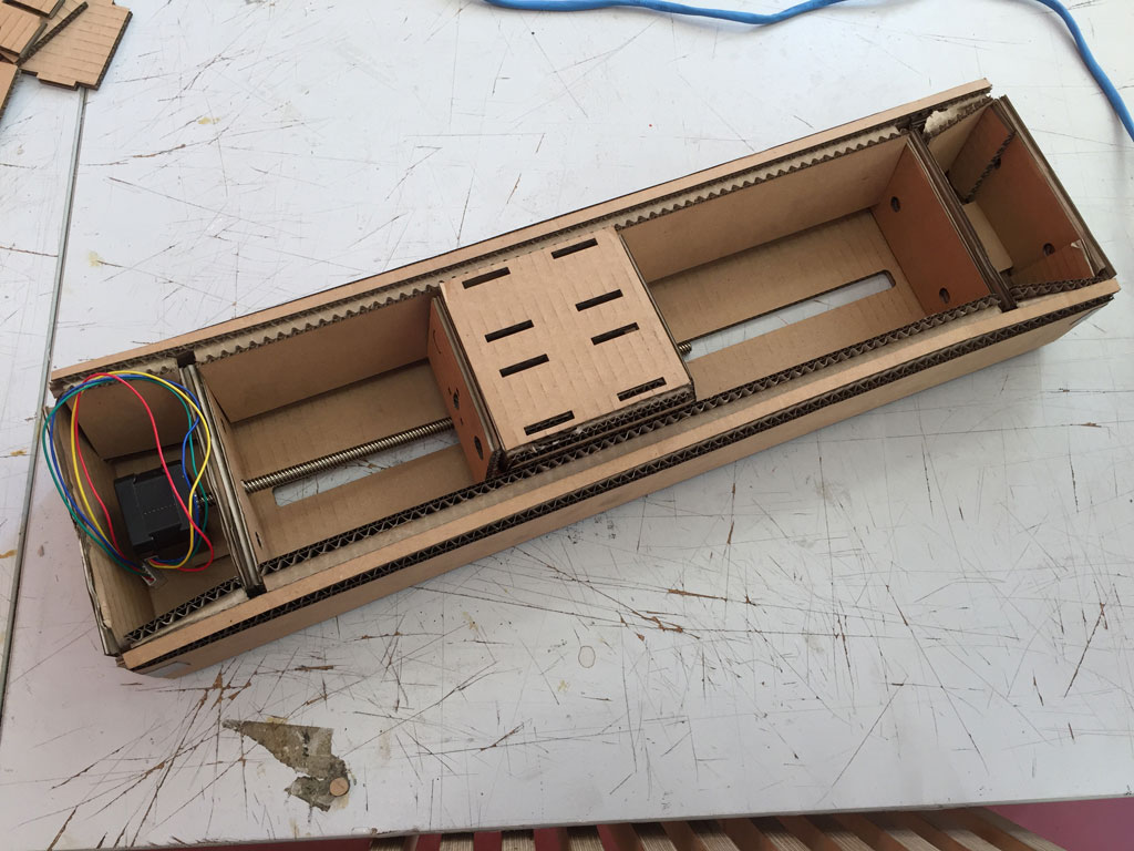
Our linear stages
Here are the linear stages.
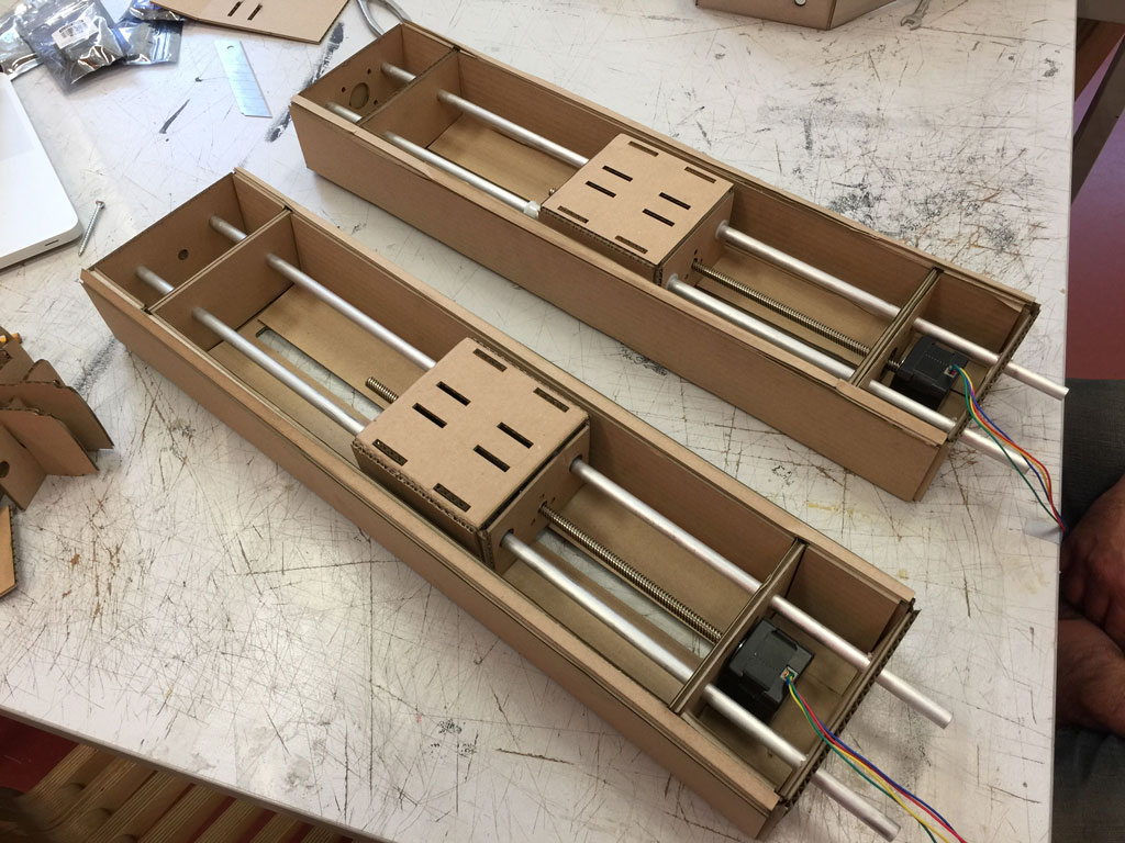
Here is a movie of the moving linear stage (with Victor's hand).
problems discussion
By building this cardboard linear stages, we spotted a few difficulties and problems:
We understand:
- the utility of 2 guiding bars
- how to fix a stepper motor to a moving linear stage avoiding backlash.
- how a cardboard kit can be easily assembled
problems:
- The quality of the guiding bars is not very good.
- lots of friction in between the bars and the plastic bearing.
- the moving plate is too thick and there is friction with the bottom of the linear stage.
- Screws are in imperial unit ! Hard to find the appropriate tools.
At the end of week 9
At the end of the week, some of us where not so happy with the idea of building a machine with this linear stages. So we thought about another project. More risky but that we enjoyed a bit more.
A drawing spider
inspiration
On Tuesday night, Victor and David discussed about this idea of making a drawing machine. On the morning of the next day, we decided as a group to build such a drawing machine. Here are some inspiration machine that Victor and David found online.
During the weekly regional review, Aldo showed us this video:
And we were also very inspired by this kickstarter project : the Maslow CNC machine.
Organizing the tasks
Denis took in charge the organization of the tasks. We divided the drawing machine into smaller parts and we assigned a leader for each part. We will work in small group on different part of the project depending on our availability. Here is the Trello that Denis has made.
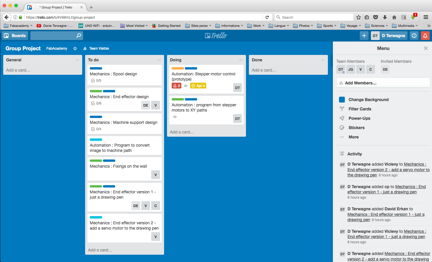
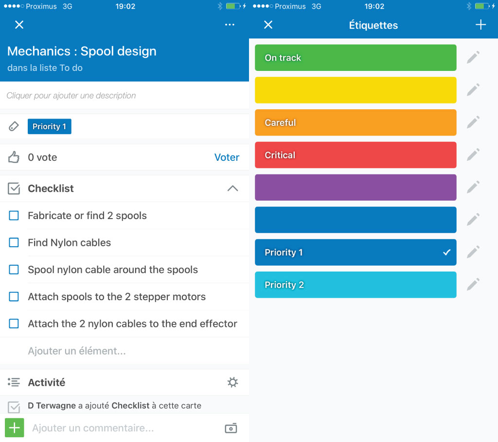
For each general tasks, we divided the work on a checklist to help anticipate the work. Denis has also assigned priority to the tasks. "Priority 1" is a task that has to be done in order to have a working machine, "priority 2" is a task to improve a working machine. The green, orange and red labels illustrate the status of each task. Green, the task is on track. Orange, the task is critical and efforts should be put on it. Red, the task is really threatening the completion of the project.
In summary, here is a general view of how the tasks are divided :
| Who ? | In charge of what ? |
|---|---|
| Victor | the end effector design and fabrication. |
| David | general design improvement and integration of the (motor, spools, cables, end-effector). |
| Jeremy | improving the machine. |
| Michele | building the prototype and in charge of the electronics. |
| Denis | the documentation, the team and tasks organization, launching the first prototype and the programing of the microcontroller. |
First prototype
Design
On several occasions, we discussed in group about the design of our drawing machine. We liked the idea of having two stepper motors on the floor and just some very light spools that we could hold on any wall, or glass window. The idea being that we could draw anything on any surface of any size...
Stepper motor control
Denis and Michele discussed on how we should program our drawing machine. We looked how machine and graphic card were working. We ended on Bresenham's line algorithm. So if we give to points, it is possible to interpolate a line in between the two points.
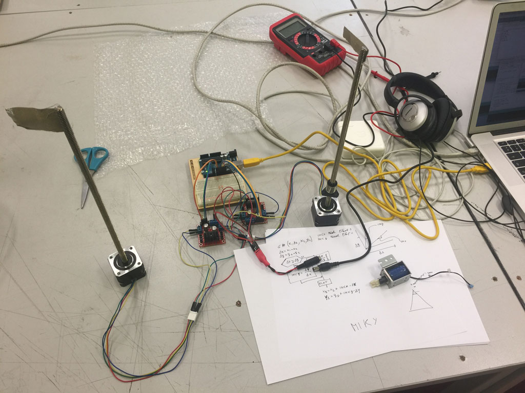
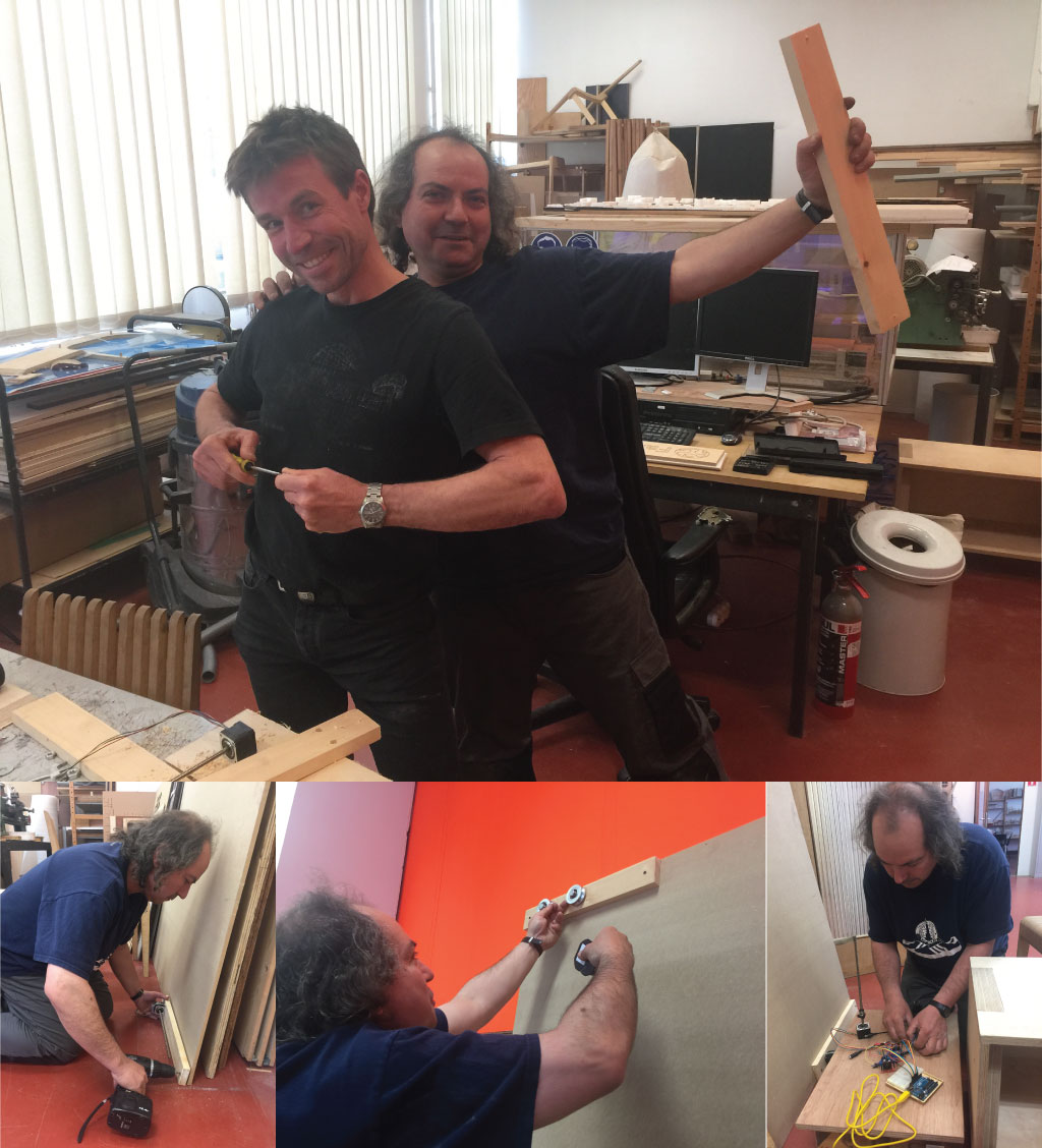
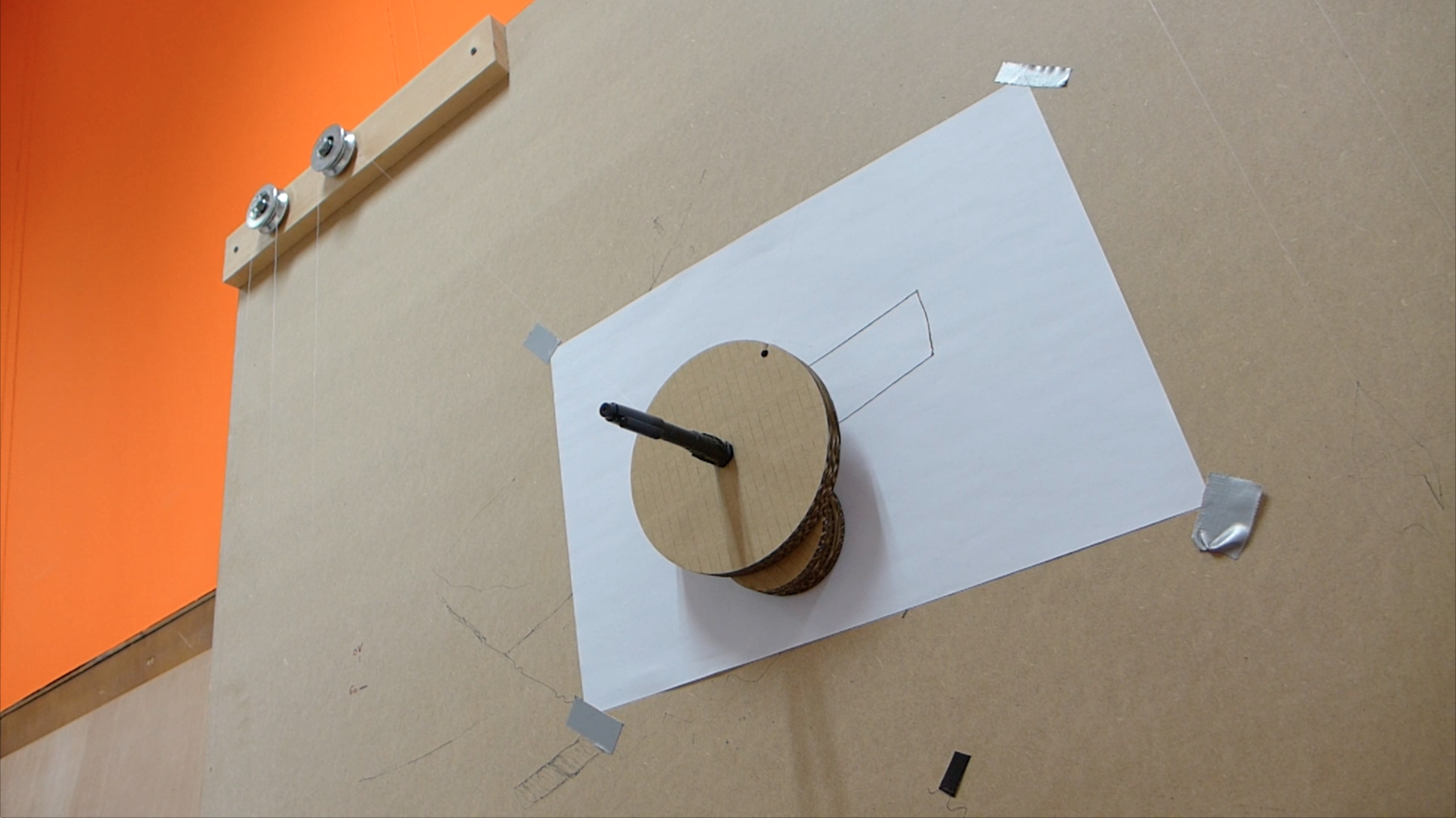
Building the prototype
That is Michele's sweet spots. He builds prototypes at the speed of light. For that he had the help of helpful student, Thierry.
Drawing programmation
Based on the morning discussion with Michele, Denis set the problem. On the figure here below, the two upper spools are separated by a distance of W. The position of a point (red point) can be expressed in two different sets of coordinates: in cartesian coordinates (x,y) and in the two wires coordinates (a,b). When we control the stepper motors, we control the number of steps which corresponds to the length of the wires a and b. The relation in between the tow sets of coordinates are:
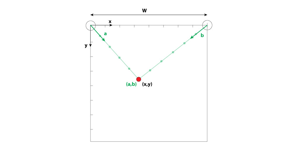
Here is an illustration of a point represented in the 2 sets of coordinates:
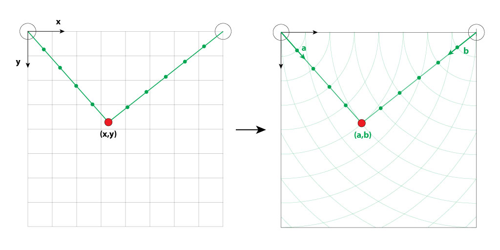
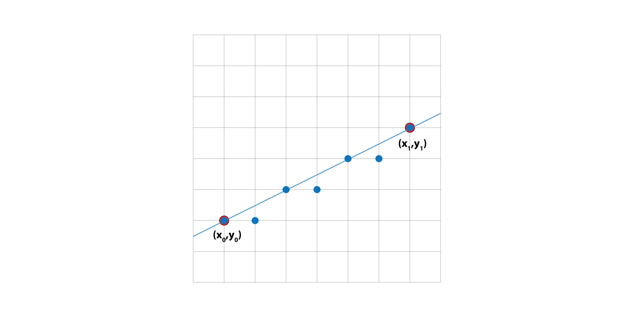
Interpolation of a line in between two points
Here is an illustration of the Bresenham's line algorithm. The algorithm finds the closest path to the theoretical lines connecting two points (x_0,y_0) and (x_1,y_1).
Program development - First tests
The stepper motors always move one after the other. So if we want to move form one point to the another, the end effector will produce a drawing that looks like half a rectangle (see the figure exercise 1 down here). If we want to draw an approximately straight line in between the 2 points, we can use the Bresenham algorithm to calculate the series of steps that each motor as to make. Each motor will move one after the other depending on how far the end effector is from the theoretical line.
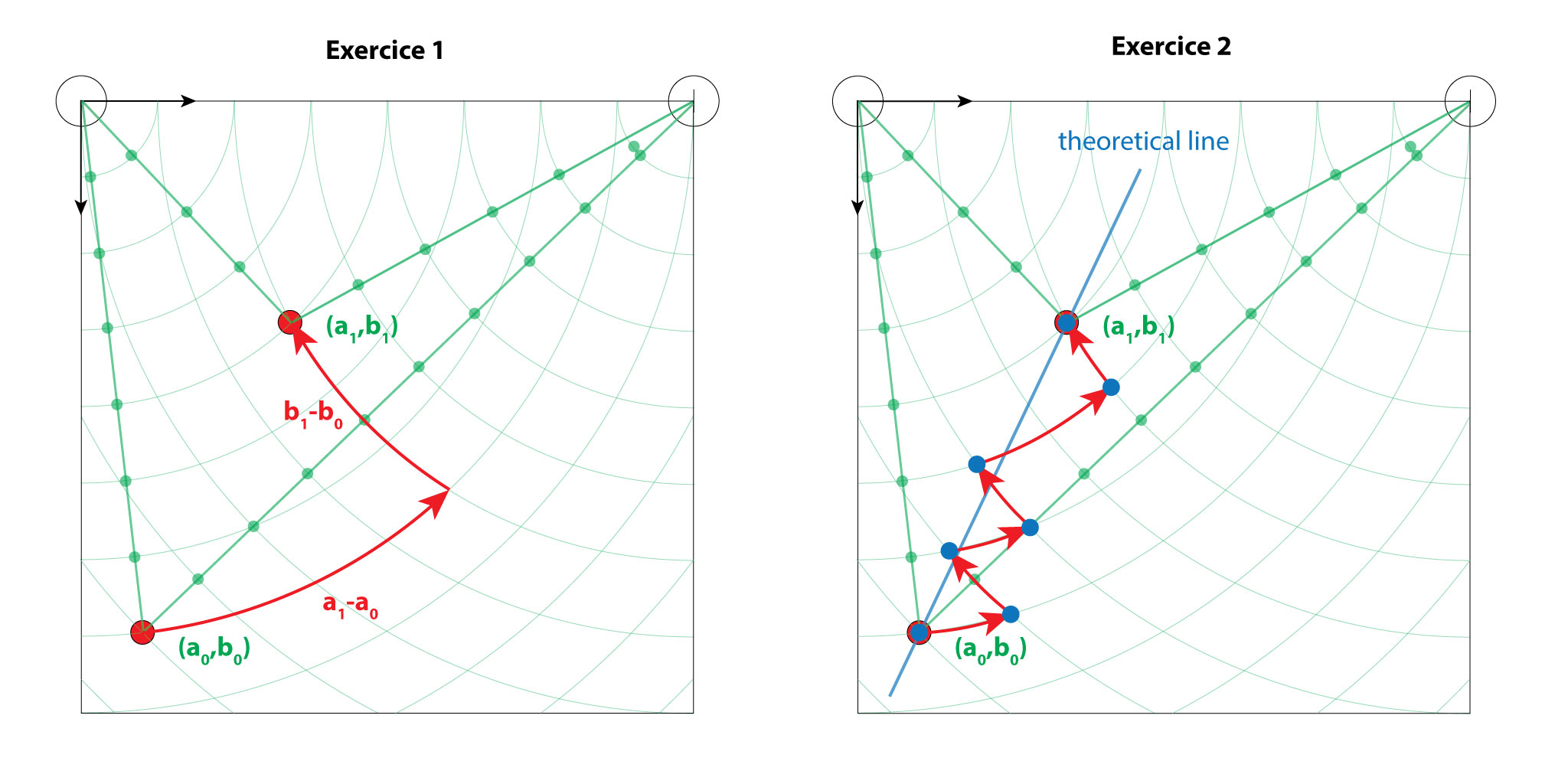
Exercise 1 - From one point to another
Moving between two points back and forth produce something close to a rectangle.
The code
Exercise 2 - Interpolating a line in between two points
For this exercise, we asked the machine to draw straight lines in a zig-zag fashion using the Bresenham algorithm.
The code
Exercise 3 - Drawing a square
For this exercise, we asked the machine to draw a square, still using the Bresenham algorithm.
The code
Improving the machine
After our tests, we can see that the machine can work but the current hardware is limiting us in both speed and precision.We need to improve :
- The motors
- the rope
- The end effector
- The conterweighs
- The electronic components
- The code
the new BOM :
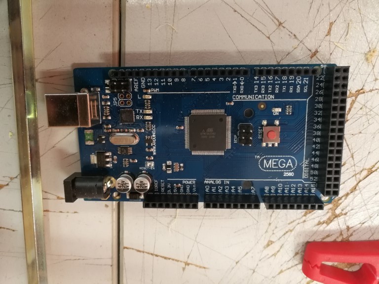
- 1 arduino MEGA
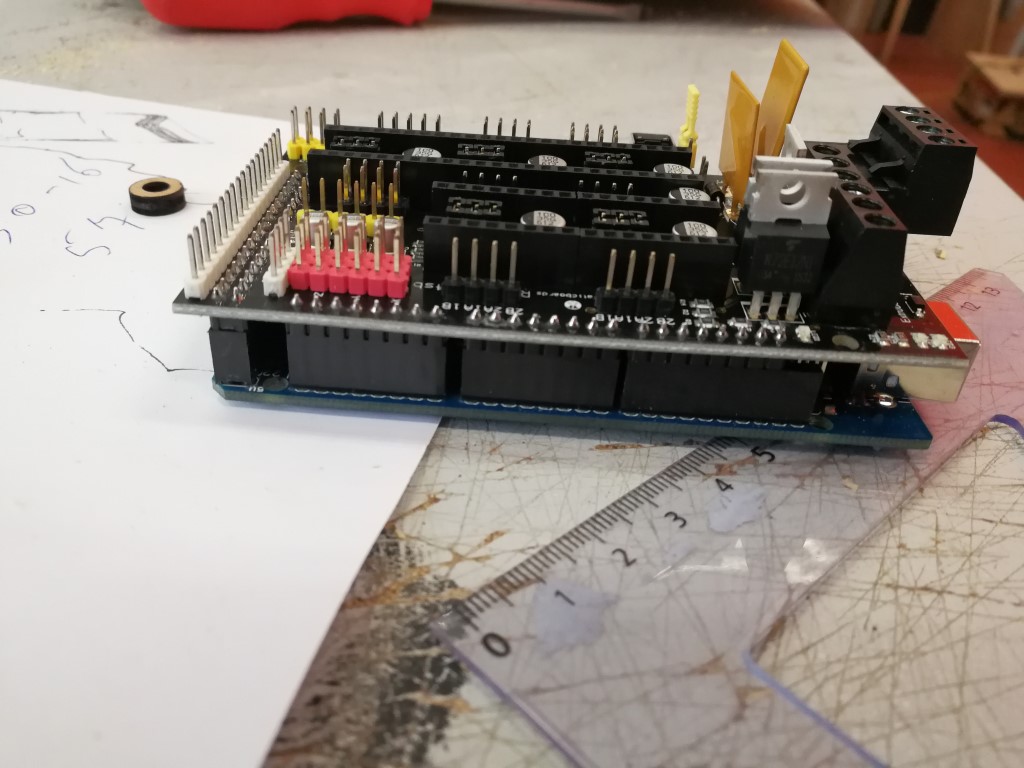
- 1 RAMPS 1.4
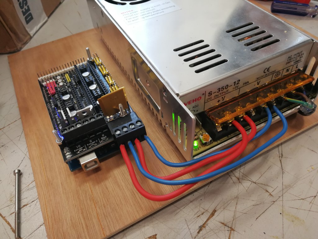
- 1 power supply 230VAC to 12DC
- 2 Pololu a4988
- 2 counterweigh from windows blind
- 2 GT2 belts
- 2 NEMA17 moto with 20 tooth wheel
- 3d printed end effector
Improving the motors
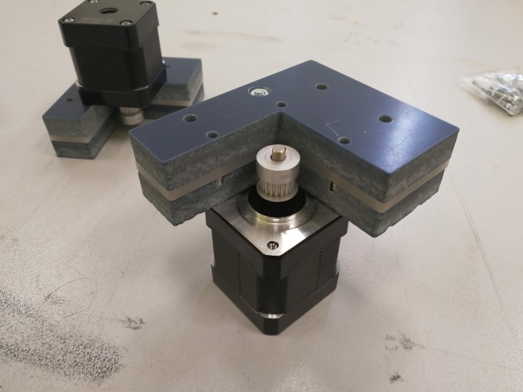
We have switch the motor in the kit for 2 Nema17 with 20 tooth wheel for GT2 belts.
Each motor is now embedded in a piece of Hi-Macs (thanks David!) and then fixed in a smaller drawing board
Improving the rope
We are now using two GT2 belts from a delta 3d printer made by ourself and now scavenged for this project
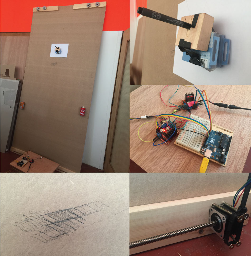
Improving the end effector
We were using different end effector for our tests and it still need improvement, especially if we want to add a step motor to move up and down the pen.
For now, we are testing this one
Improving the counterweight
After the cans, we tried the counterweight from our window blinds and it's was working pretty well! We can open them to adjust the weigh
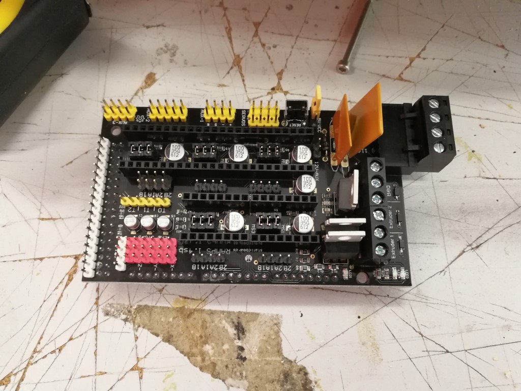
Improving the electronic components
We have changed a lot from our initial setup. The base is now a Ramps 1.4 with an arduino MEGA and 2 Pololu a4988 configured for 1/16th microstep. To power all of this, we are using a power supply 230VAC to 12VDC This setup allows us now to be much more precise and to reach a greater approximation value for our drawing
Exercice 4 - Writing letters
This is of course the trickiest part. Thanks to Denis, we have now a solid piece of code to start but a lot of things need to be changed (new electronics, size,...)
For this part, a friend of mine, Benoit Sobrie, help us a lot, thanks again!
For now :
- we convert X,Y coordinate to A,B belt length.
- Write the letter F and A.
- Use RAMPS as controller.
The code
Last improvements
We have made some last minutes improvments for both the code and the end effector. We can now write FABLAB and others words easily!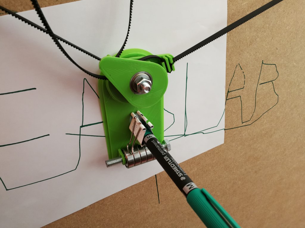
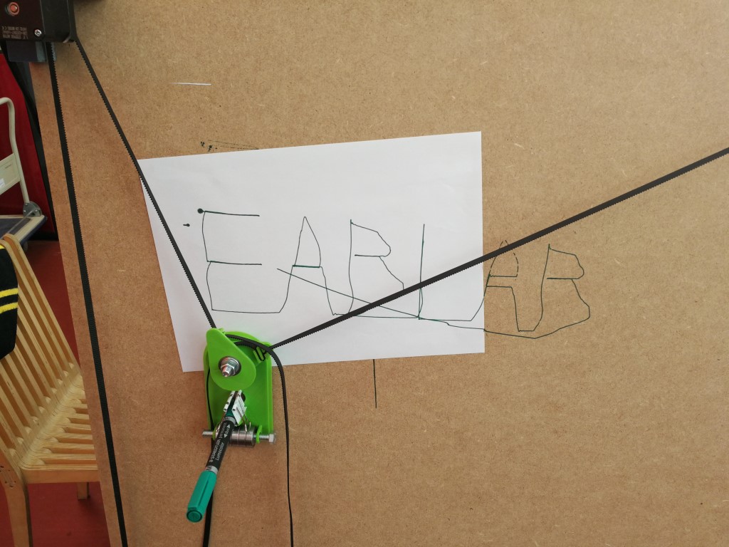
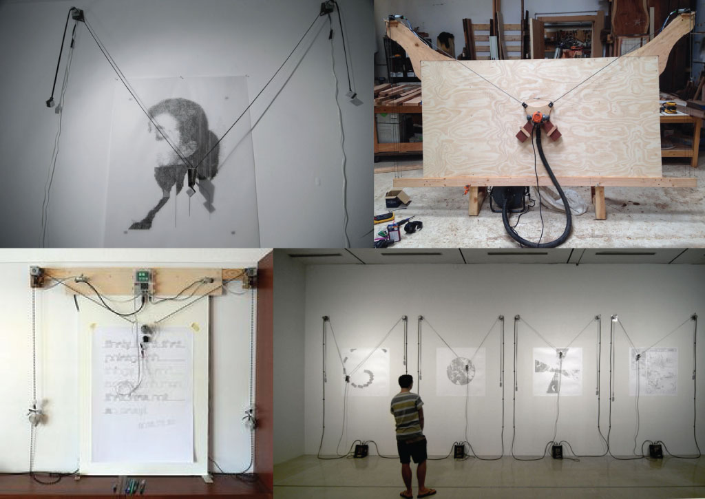
A drawing machine made by one of our students
Updated on June 28, 2017
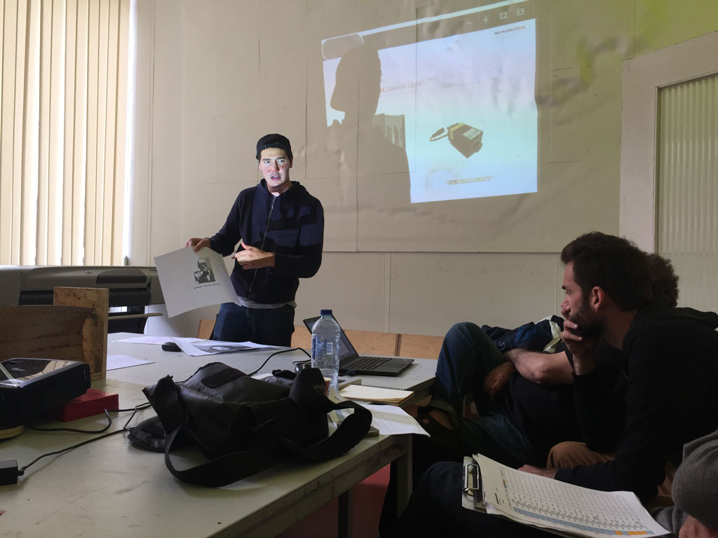
Today was the final presentation of the semester long class Digital Fabrication Studio DFS taught by Victor Levy and David Erkan at the faculty of architecture at the Université Libre de Bruxelles (ULB). Students follow a creative process, they design and fabricate something of their choosing. Today, Valentin Breul, a student following this course, presented the drawing machine he fabricated which works really well. Prior to this class he didn't know anything about electronics, stepper motors, motor drivers, Arduino, C code and interface programming but he managed to build a working machine.
We thought it would be nice to present parts of Valentin Breul's work which is in the continuity of ours.
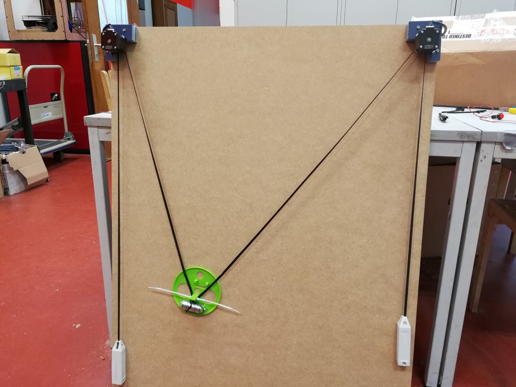
Here is the machine he made.
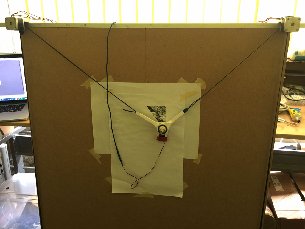
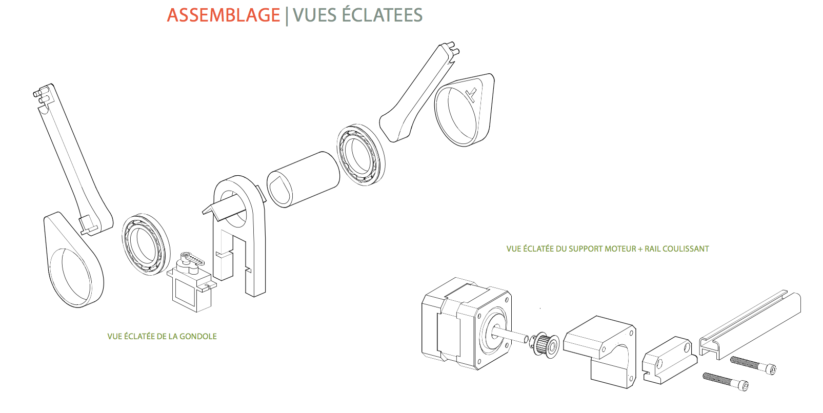
Inspired from existing machines, he designed and fabricated the end effector using 3D printed parts and a servo motor so he can hold back the pen from the drawing board.
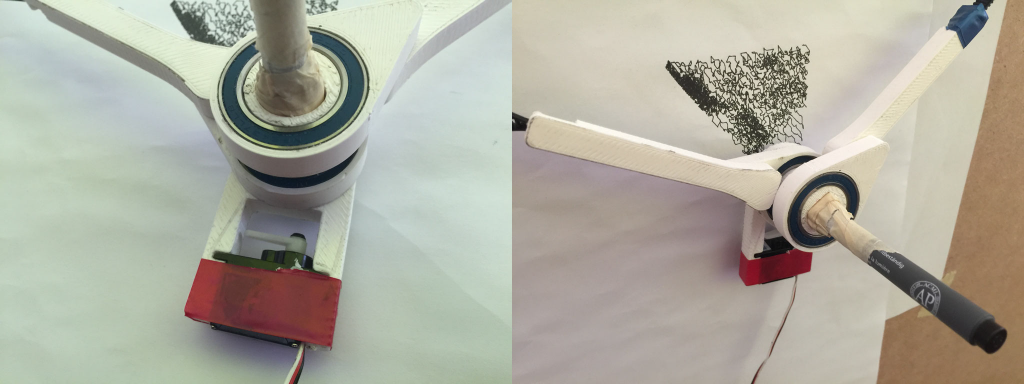
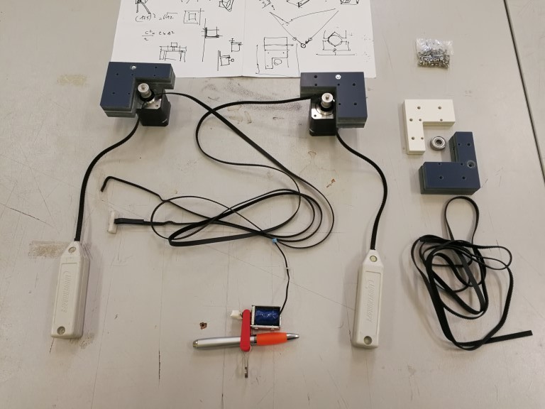
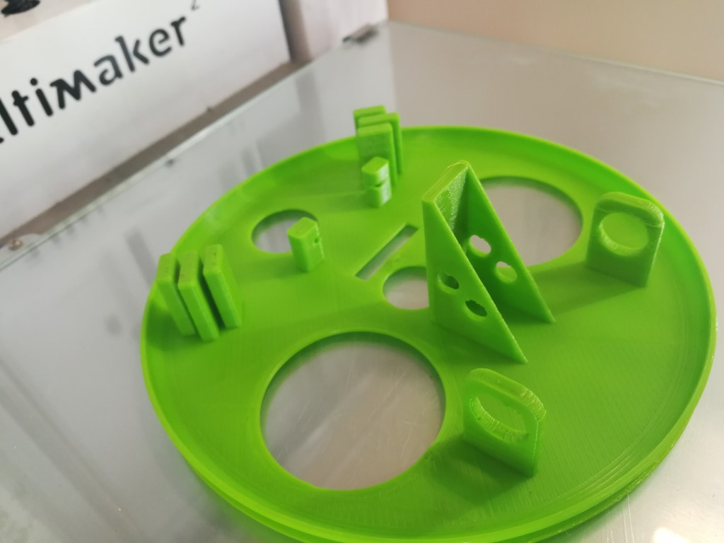
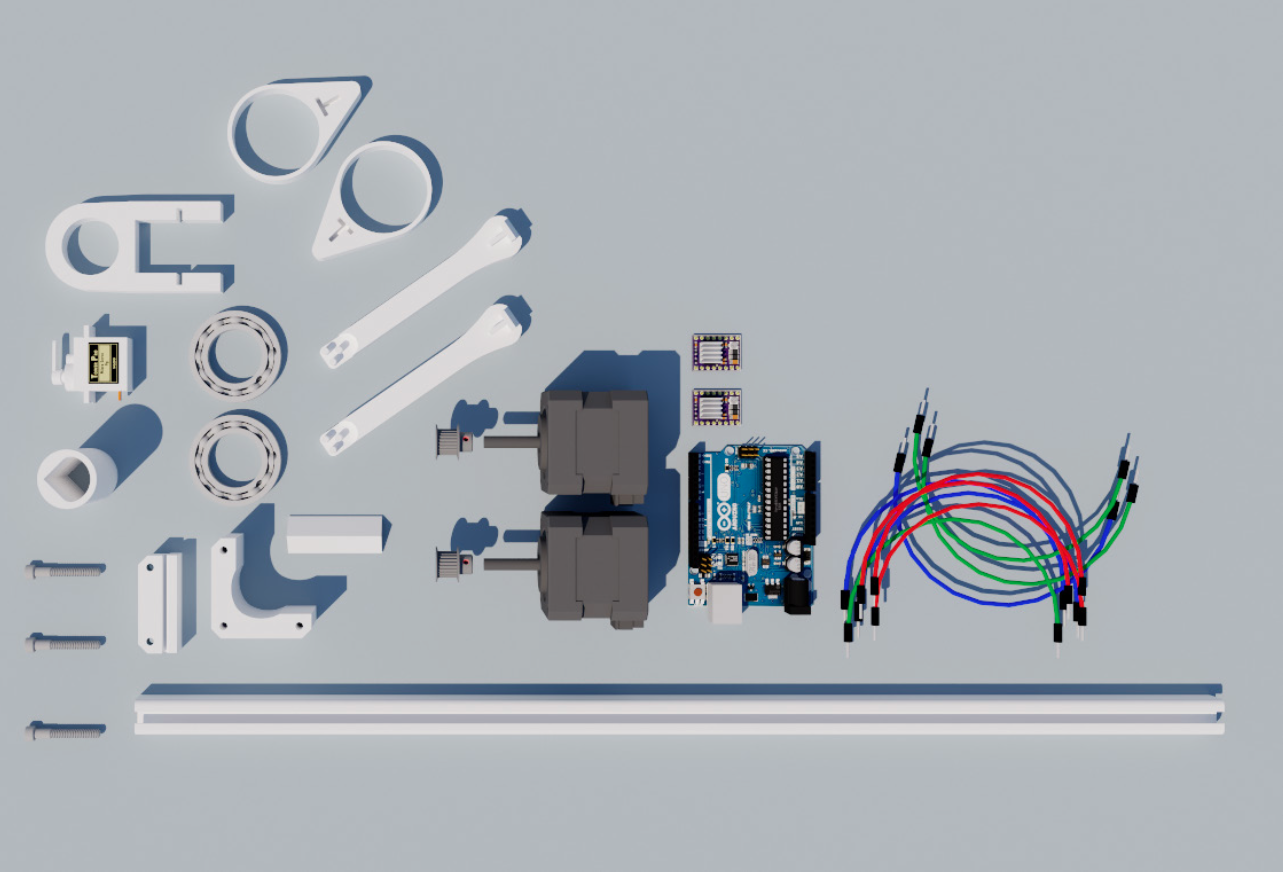
Here are all the components and the pieces he designed, fabricated and used to make his drawing machine.
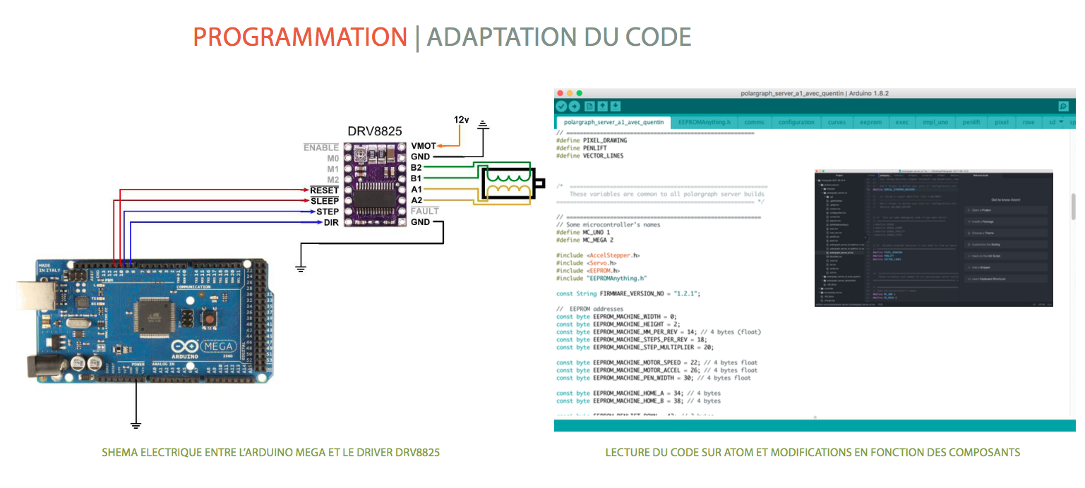
To make the stepper motors work and control the end effector, he adapted this code to program the Arduino.
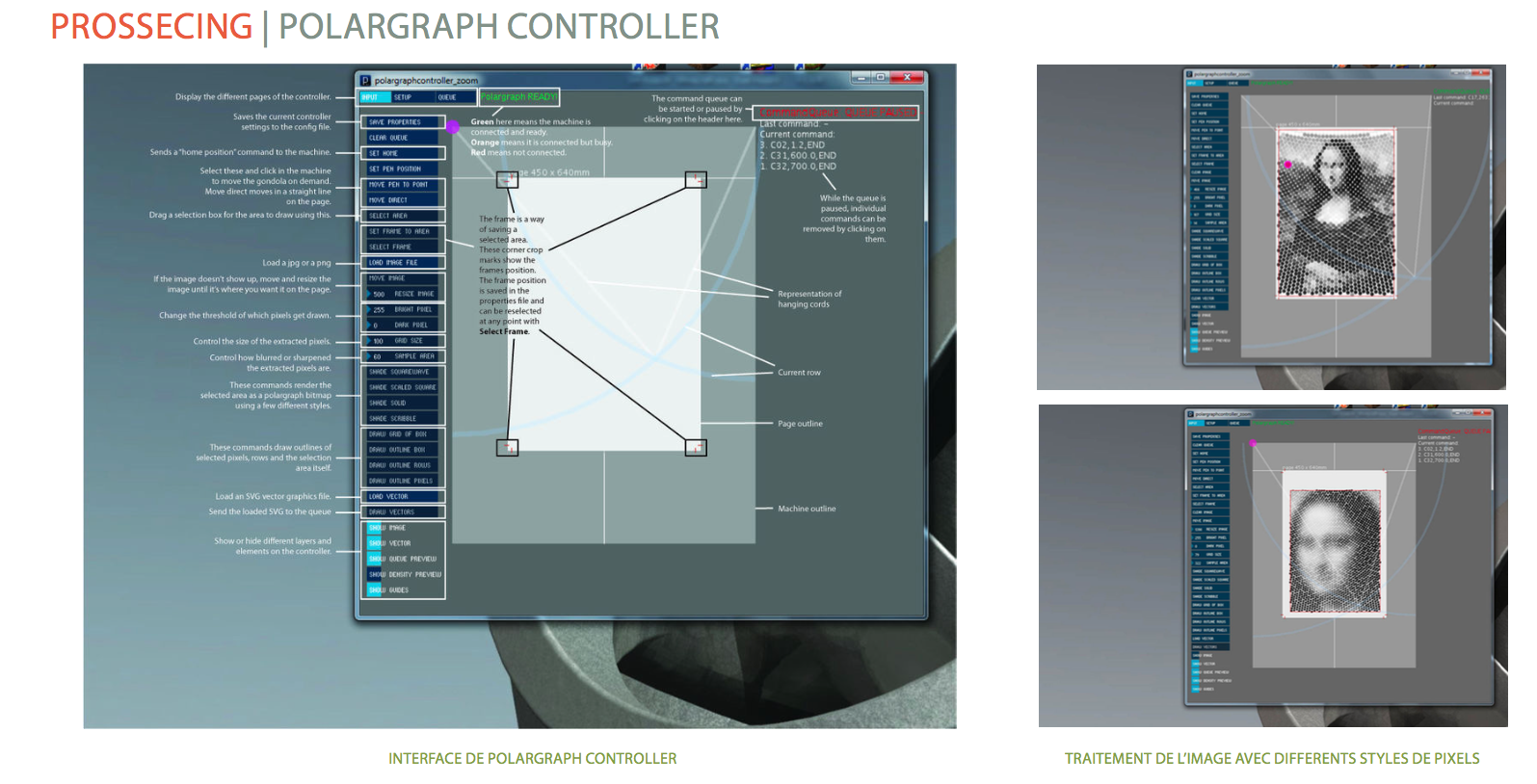
To make the programming interface in between the sketch upload and the toolpath sent to the Arduino, he adapted this polargraph controller. made in processing.
Finally fabricating this machine, he learned a lot about various softwares and hardwares.
Here is a video of his drawing machine.
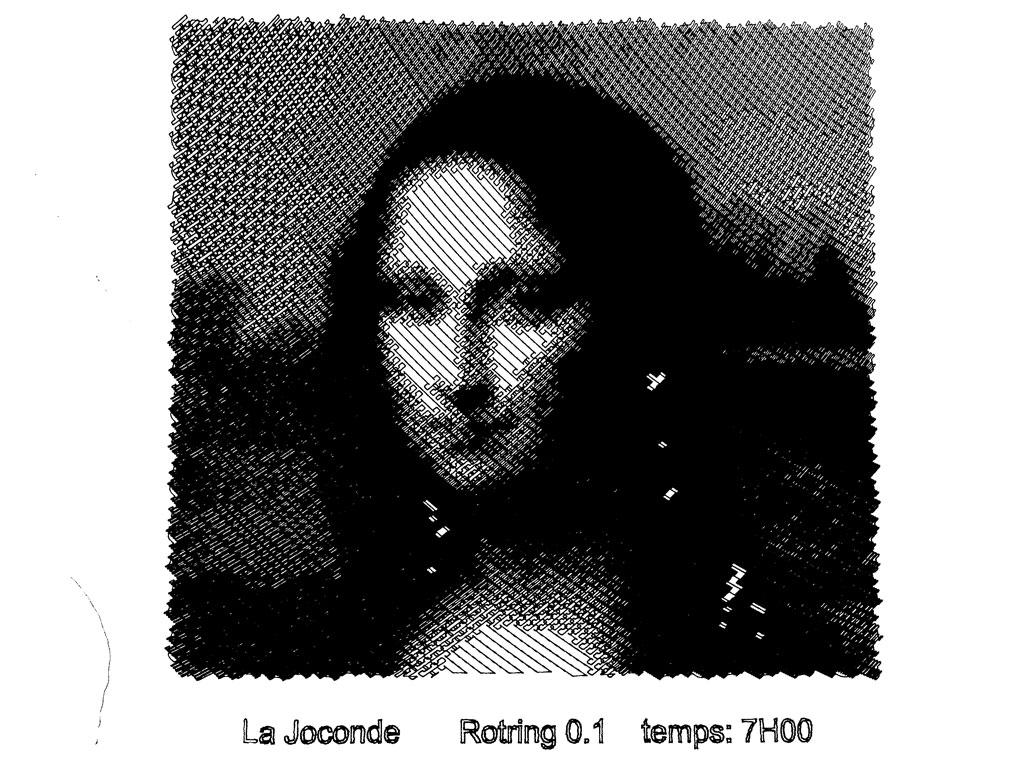
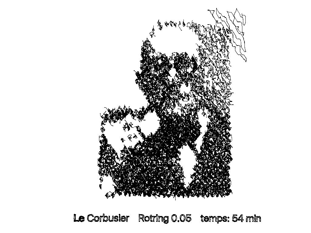
Here are some of his drawings.