Week 5 - 3D scanning and printing
- test the design rules for your printer(s)
individual assignment:
- design and 3D print an object (small, few cm) that could not be made substractively
- 3D scan an object (and optionally print it) (extra credit: make your own scanner)
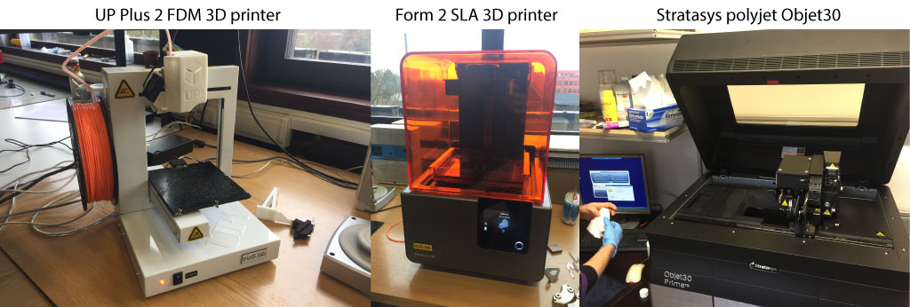
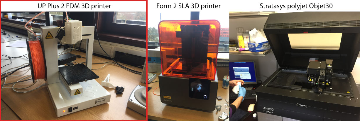
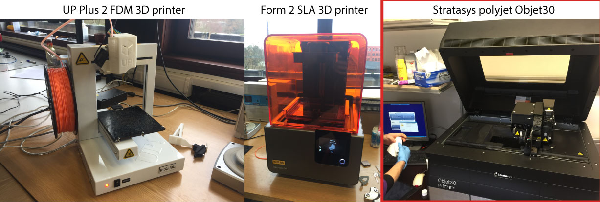
- UP Plus 2 3D Printer A small FDM 3D printer, cheap and very reliable
- Form 2 SLA 3D Printer A desktop SLA 3D printer, affordable and very high resolution.
- 3D printer Stratasys Objet30 A high resolution but more expensive polyjet 3D Printer.
- Next Engine 3D scanner A very high resolution desktop 3D scanner that is easy to use.
Softwares :
- Fusion 360 A 3D design tool.
- NextEngine ScanStudio
This week, I really wanted to explore different 3D printers with different technologies and compare them. That's why we chose the tugboat design as a torture test that we printed on a FDM 3D printer, a SLA 3D printer and a polyjet 3D printer. This first part took some time to be made so I had to come back later on the rest of the assignment. I then tested the 3D scan performances of the Next Engine 3D scanner by scanning the 3D printed tugboat. Making a complete and precise 3D scan requires practice and lots of post processing. Finally, I've 3D designed a Tippe-top (based on a sphere shell) in Fusion 360 that I've printed using the SLA 3D printer.
Some definitions
Here are some definitions of the 3D printers jargon.
| Term | Definition |
|---|---|
| FDM | Fused Deposition Modeling, an additive manufacturing technology that consist in melting a polymer wire and adding layers of melted polymer on a platform to form an object. This is the most common way of 3D printing. |
| SLA | StereoLithography Apparatus, a 3D printing technology that uses light (UV) to crosslink a liquid polymer and make a solid object, layer by layer. Usually, the objects are printed upside down and are pulled out of a liquid resin tank. |
| PolyJet | a 3D printing technology that works similarly to inkjet printing. Those 3D printers jet layers of curable liquid photopolymer on a building platform. |
Comparing different 3D printers and technologies
As a start of this week and group assignment, we wanted to test the limits of our different 3D printers and compare different technologies. We have several 3D printers at the Fablab ULB and in my lab.
We chose to compare :
- UP Plus 2 3D Printer - a FDM 3D printer
- Form 2 SLA 3D Printer - a SLA 3D printer
- Stratasys Objet30 3D printer - a polyjet 3D printer
Choosing a torture file to challenge our 3D printers
Jérémy sent us two files that would be interested to print to test our 3D printers.
UP Plus 2 3D Printer
We upload in the UP software the STL file of the 3D benchy tugboat that can be found in our source file.
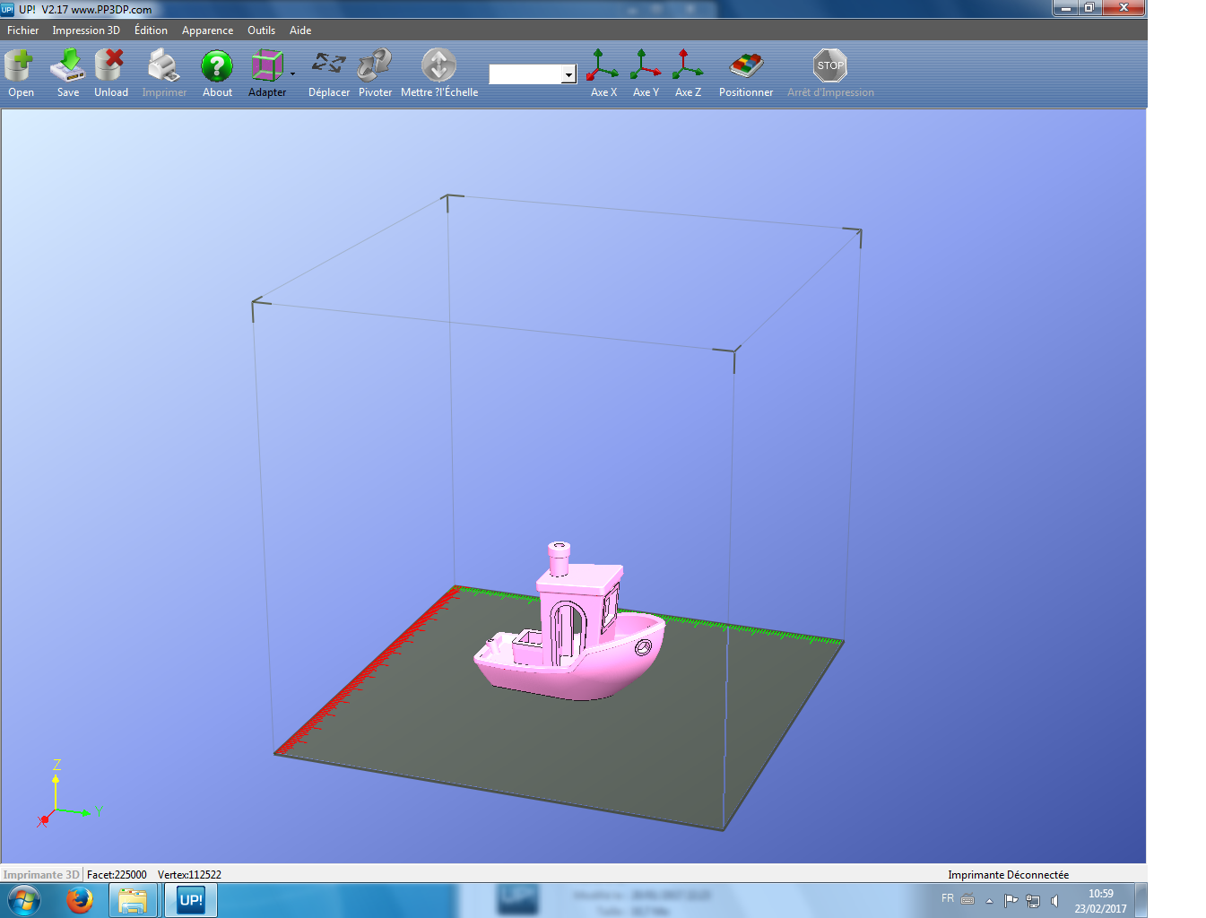
We whose the 3D printing settings.
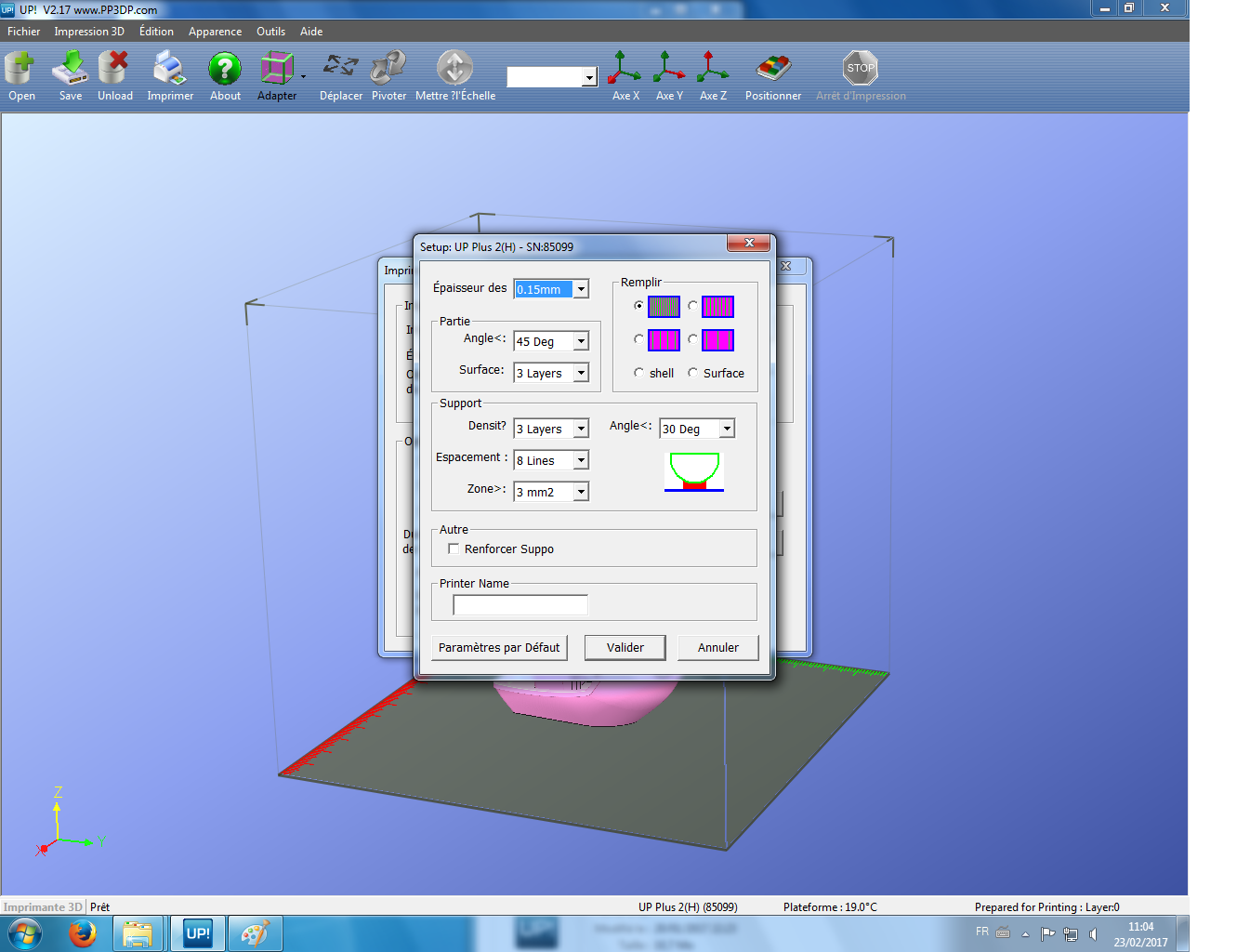
We print the model. It will take less than 4 hours and 18g of ABS plastic.
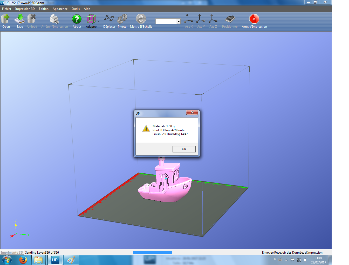
Here is a movie of the Up 2 plus printing the tugboat torture test.
Form 2 SLA 3D Printer
This printer is an incredible 3D printer has printing is highly precise. We have just to be cautious when manipulating the resins and also when we clean the 3D printed parts at the end of the process. Here are the basic finishing steps.

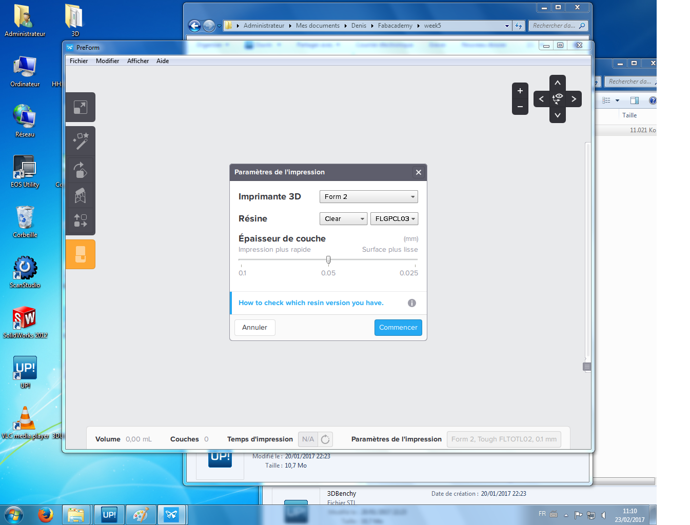
We used a clear resin ( reference here ) for this printing. Resolution is set to 50µm for a standard printing. Higher resolution is possible but it will take more time to print.
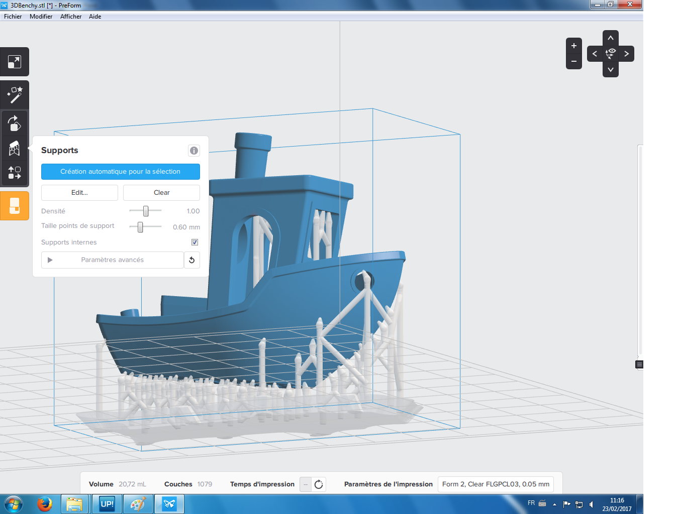
With this printer, to support the arches, the printer will print resin beams in the same material than the building material that will have to be removed at the end of the process. Conversely to the FDM printer up here, it is best with SLA printers to tilt a little bit the flat surface so the object do not detach will printing it.
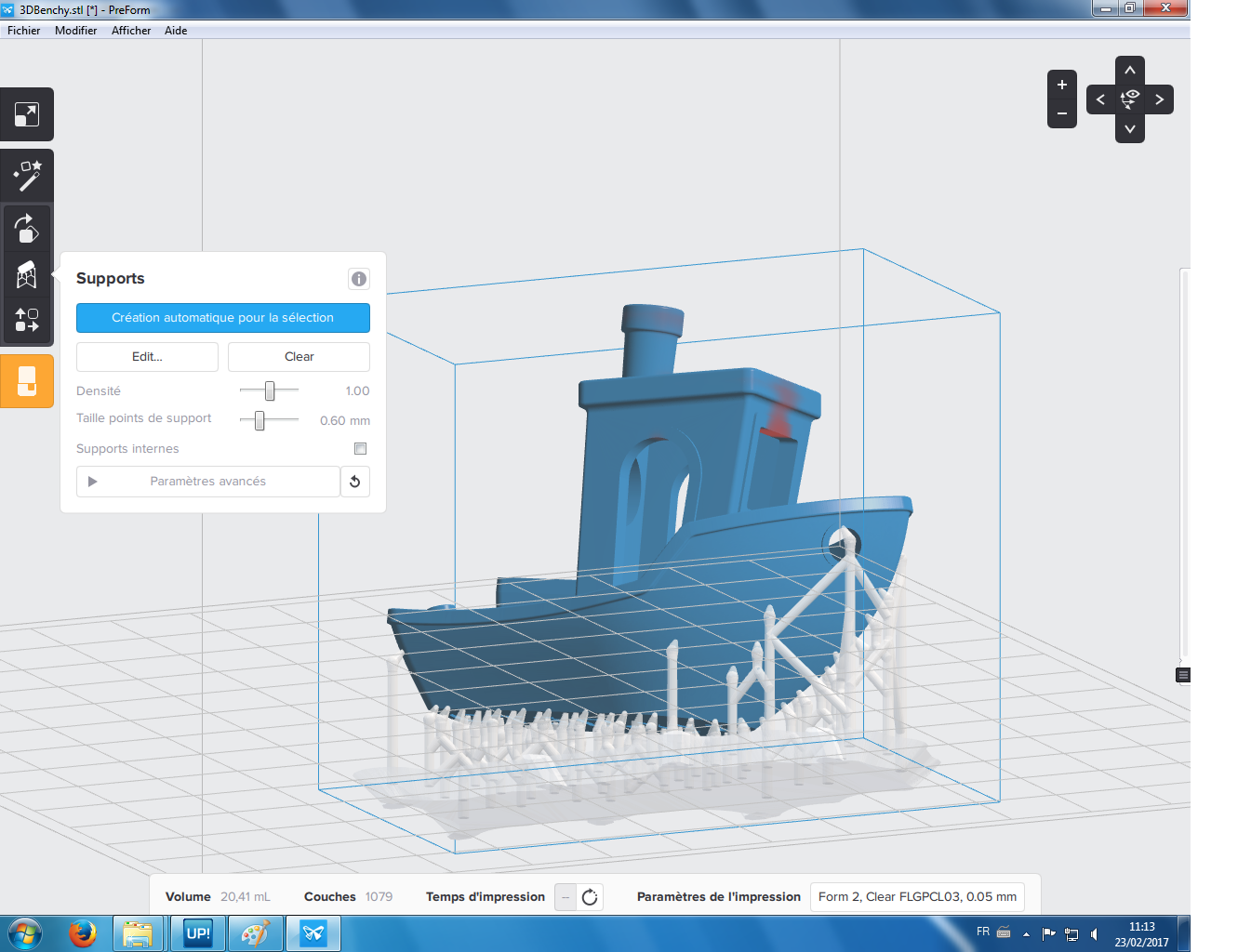
Overhang surfaces can be problematic to print. If there are no support materials or beams, the printers won't be able to print these parts. The Preform software allows you to see the problematic parts for the printer (the red surfaces on the image up here and here below). We thus have to add a few beams to support the overhang surface while printing the object. This procedure can be made automatically or manually. We chose to do it manually.
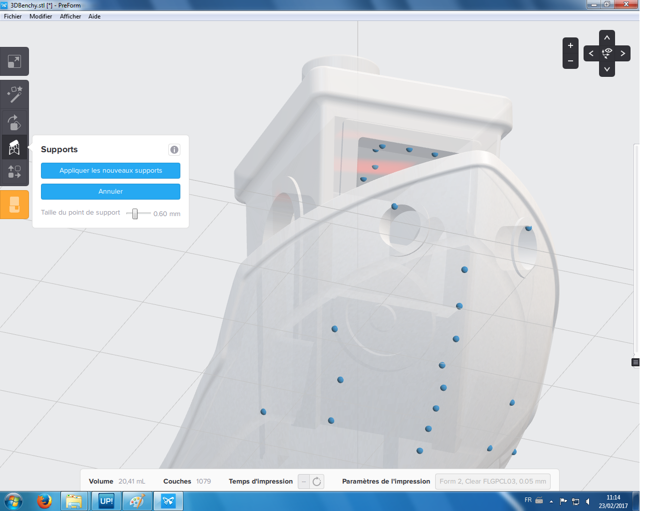
Here is where we add the support beams.
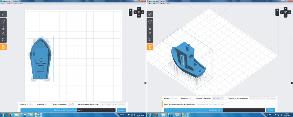
The 3D drawing is set on the platform. It is ready to be printed. The object will take 4h30min to print which is similar to the Up 3D printer.
Here is a movie of the Objet 30 printing the tugboat torture test.
Stratasys Objet30 3D printer
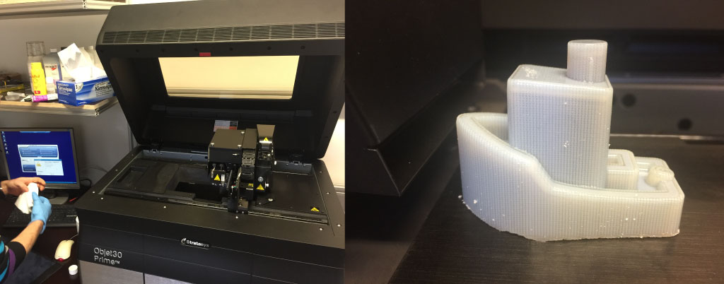
While I was visiting the group in which I have done my PhD thesis at the University of Liège, I took the opportunity to test their Objet30 3D printer. This machine is quite impressive. It is very high resolution but quite expensive. It costs around 30 to 50 000 Euros. Maintenance is high. Cleaning as to be made regularly at least once a week. Polymers expire really fast (around 6 months) and materials is quite expensive. If the 3D printer is not running flushing of the printer is needed. The printer has to run on a regular basis. The best part of this printer is that they are highly precise and easy to use.
With the Objet30, two materials are used: a building material and a supporting material. There are no problem at building arches has the support material fully fills the empty parts of the object. A mat or shiny finish of the 3D printed object can be obtained by printing a layer of support material everywhere, removing it at the end produce a mat finish. If no support material is deposited on the last layer of the object it will stay shiny. Here the object will be mat has the object is entirely embedded in the support material.
This printing was made in standard resolution and took 5h30min (highest resolution is possible but it will take 9 to 10 hours to print). It will use about 60grams of materials (30g of building materials and 30grams of support materials). It is 4 times more than the UP 3D printer and it is far more expensive (but results are different).
Here is a movie of the Objet 30 printing the tugboat torture test.
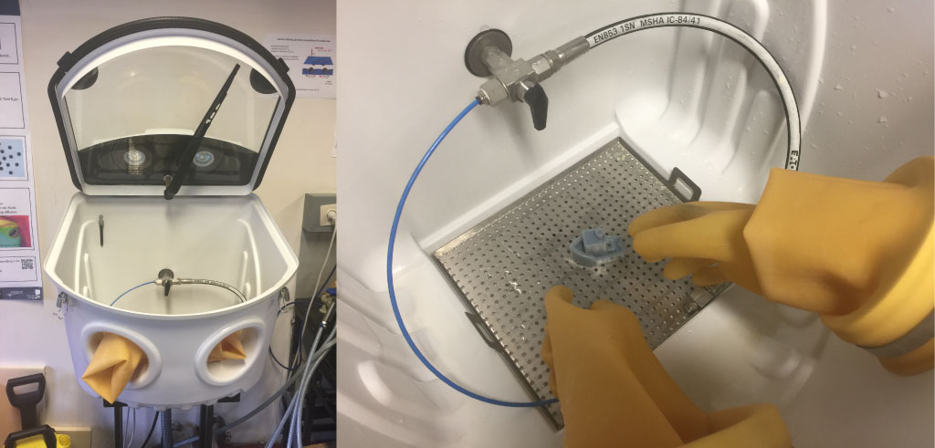
To remove the support material we just have to use a high speed water jet. Really easy.
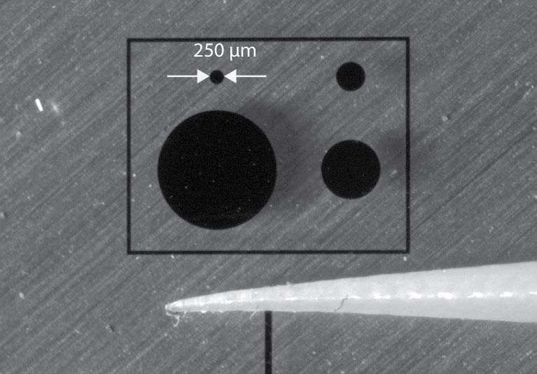
Maximum resolution of the Objet30
Here is a microscopic view of a printed pointy cone. We see that this printer is able to print pointy heads with a resolution of about 100µm.
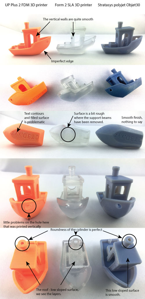
Analyzing the tugboat 3D printed object
How to make the comparison ? Here is a list of what to check on the different 3D printed objects
3D scanning the tugboat
I then wanted to 3D scan the tugboat I've printed using the Next Engine 3D scanner.
3D scanner setup
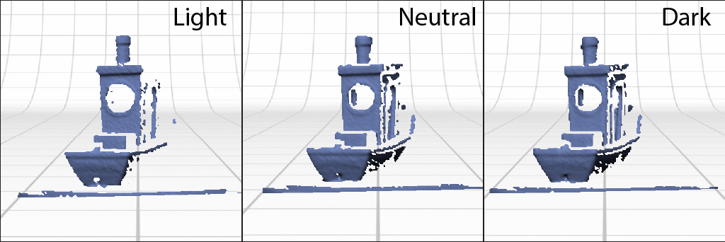
I opened the NextEngine ScanStudio software and started a new scan. I chose a positioning of 360 which means the scanner will make different scans of the tugboat from different sides (making a whole 360° turn). We can also choose the numbers of scans the scanner will make while the tugboat turns (here under it is written 8 but we can use much more if we want more precision). We can also use different resolutions. For the scans below I used the maximal HD resolution that is available. Depending on the surface of the object, "light", "neutral" and "dark", the scans may be more effective (see the images below). Dark was the best option here. I also used a "macro" range as the tugboat is quite small.
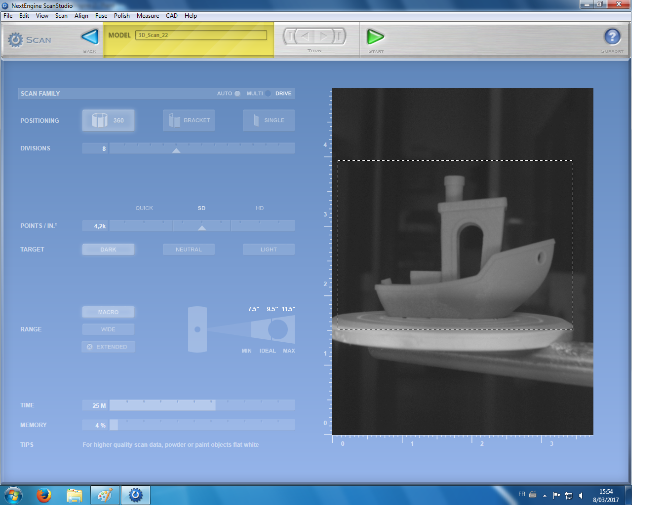
The "target" setting can be set on "light", "neutral" and "dark" depending on the texture of the object."Dark" seems the best option here.
Alignment of the different scans
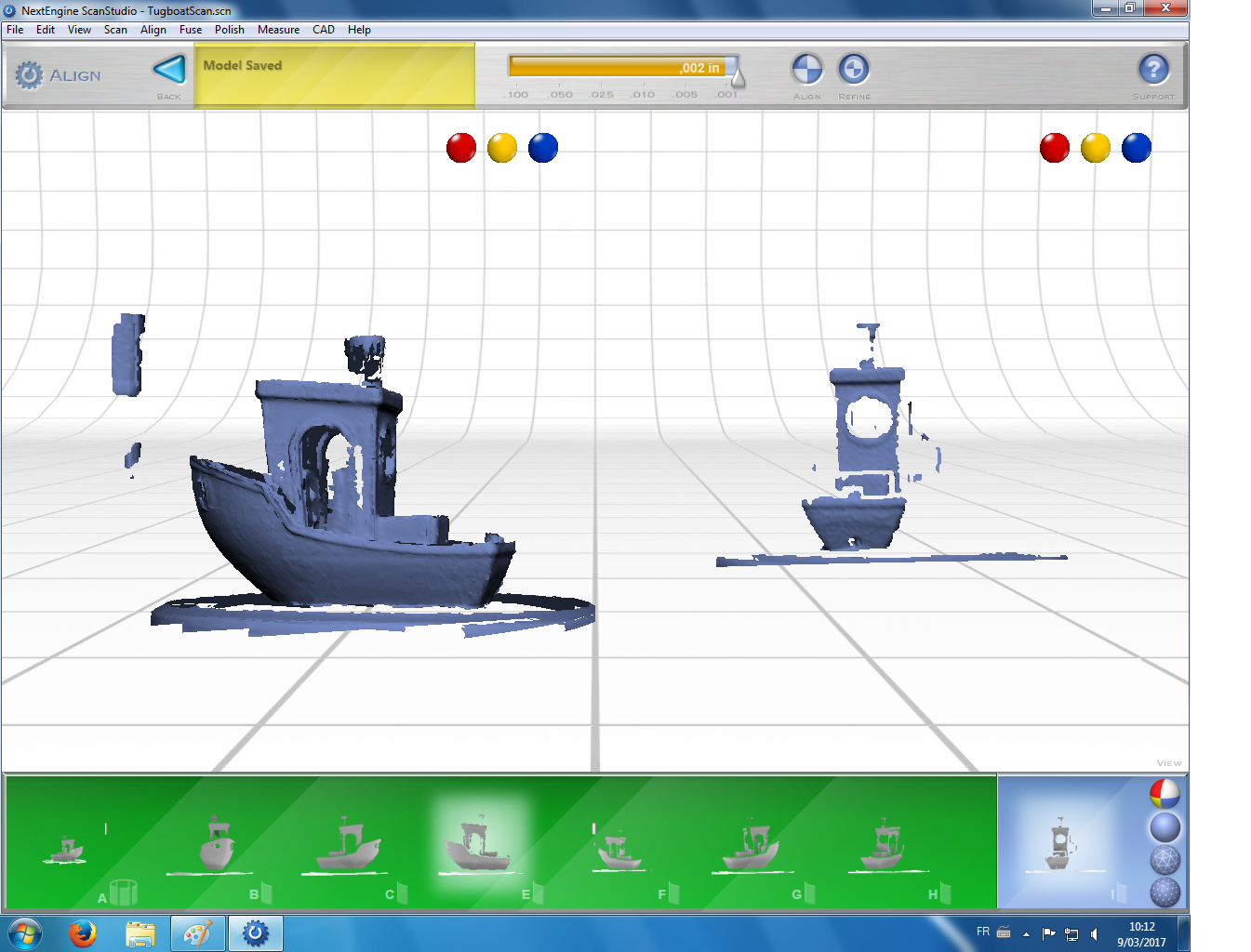
After having made all the scans of the Tugboat from different angles. The software is able to recompose the full 3D object.
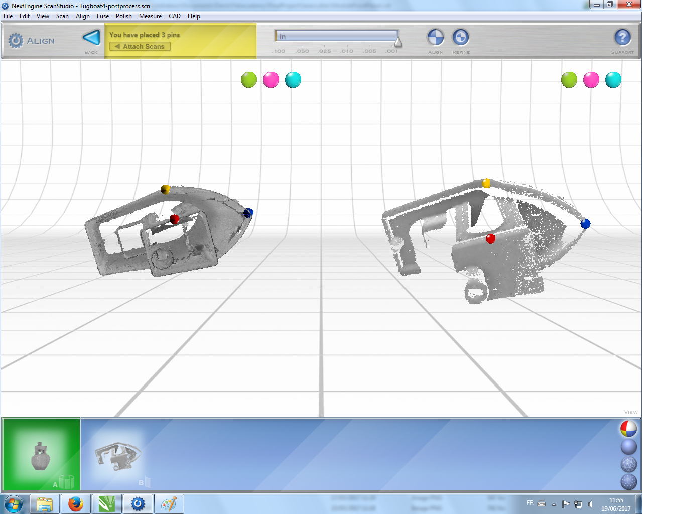
Sometimes the software needs a little help to align the scans. There is a way to do that using the "align" tool. Opening the two parts that have to be aligned, we can add pins on both models on parts that should be superimposed. Then by drag and dropping the thumbnail of the right scan in the lower part of the screen on top of the other one in the green area, we will see if the alignment works.
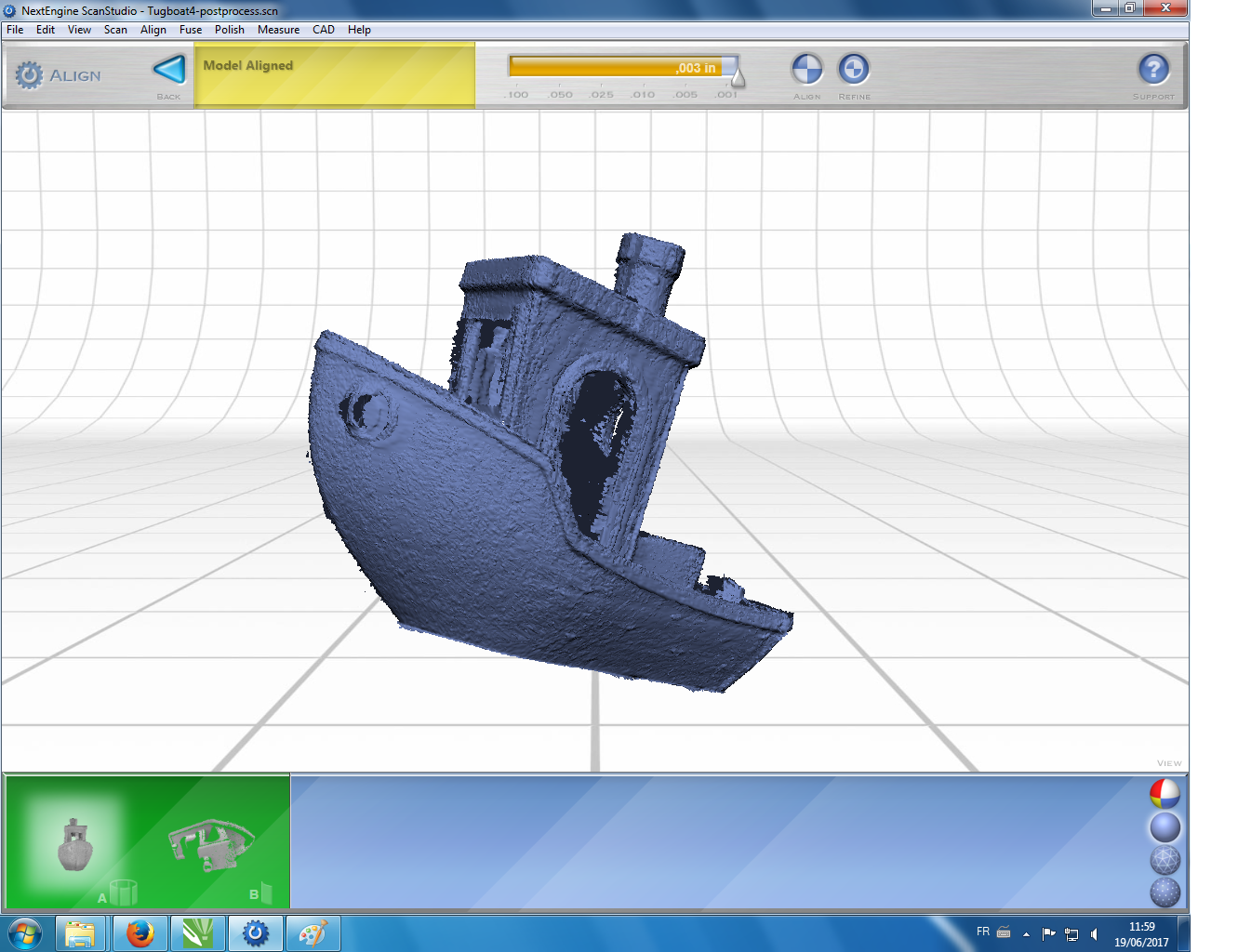
To improve the alignment, we can refine the model alignment using the "refine" tool.
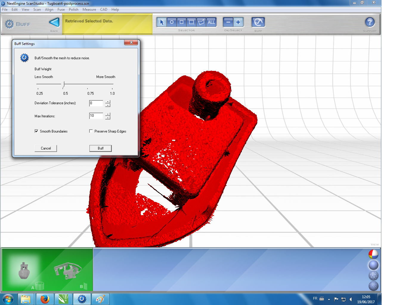
Smooth
The final assembled scan can be post-process. Here for example, I performed a smoothening of all the tugboat surfaces using the "bluff" tool. Holes in the surfaces can also be filled and the mesh can be simplified. This can be helpful if we want to 3D print again our tugboat.
Hero shot
Here is the final scan that comes from an assembly of multiple scans from the side and the top. Manual assembly of some of the scans was sometimes required and a smoothening of the surface of the final 3D object has been performed.

Designing and 3D printing a Tippe-Top (updated on 3/5/2017)
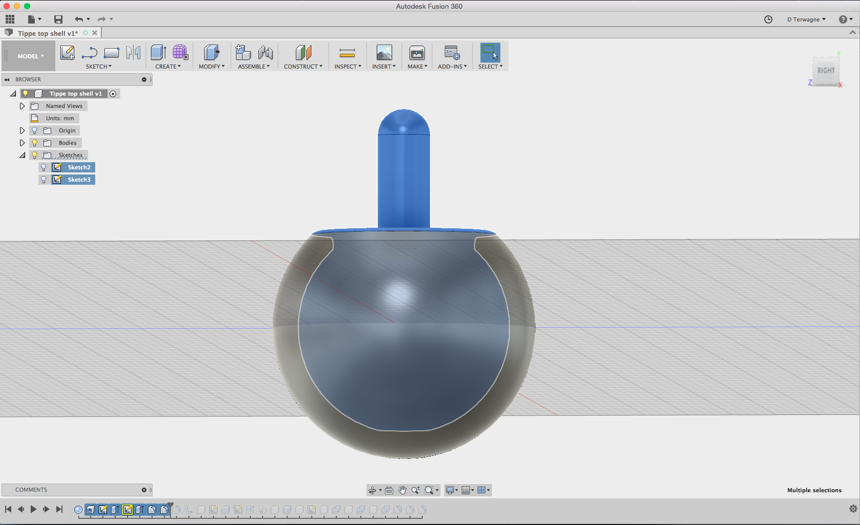
3D designing the tippe-top
For this part, having learned Fusion 360 during the Fabacademy, I decided to 3D print a Tippe-top with an outer shell that is difficult to make with something else than a 3D printing machine.
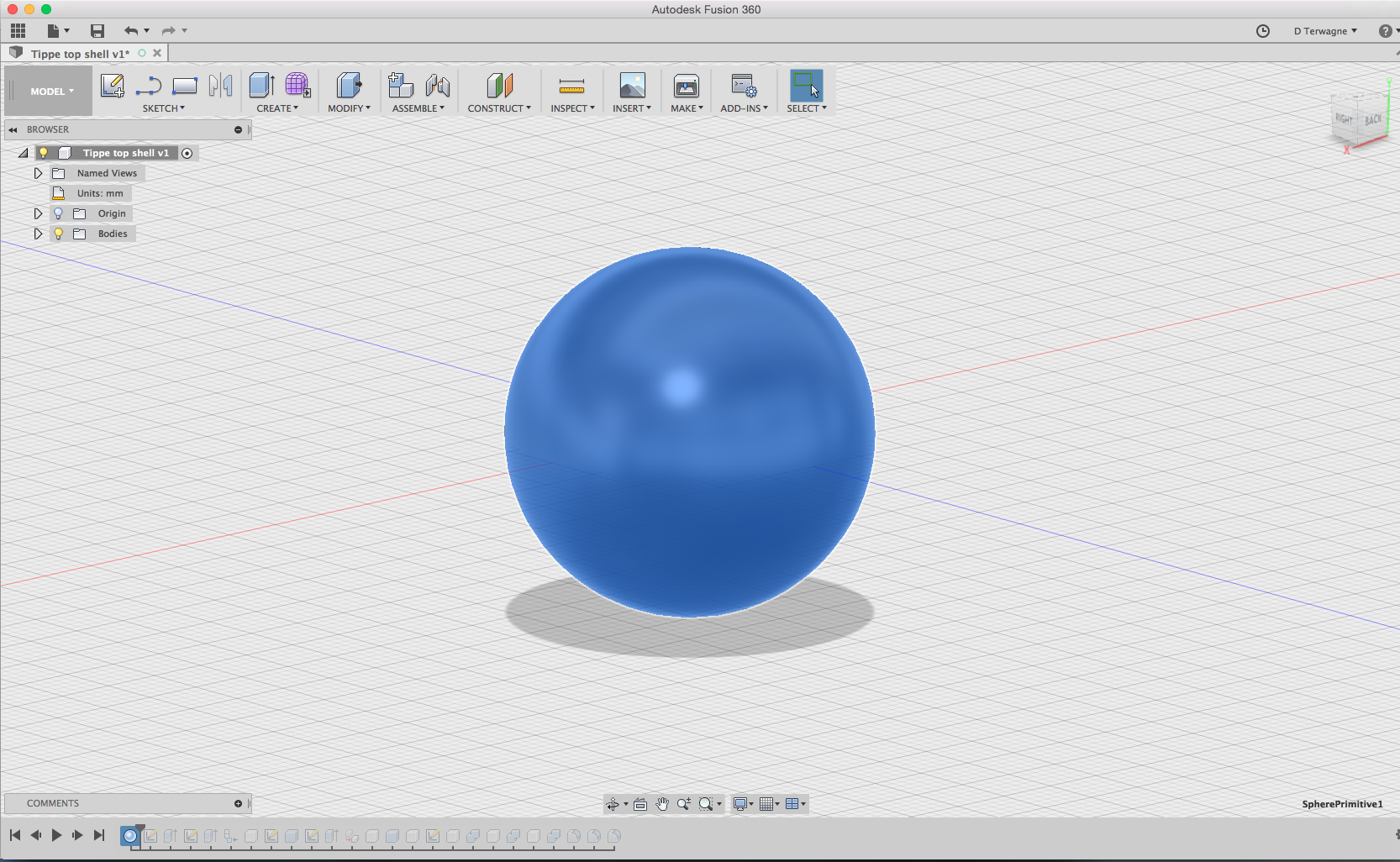
I started with a sphere.
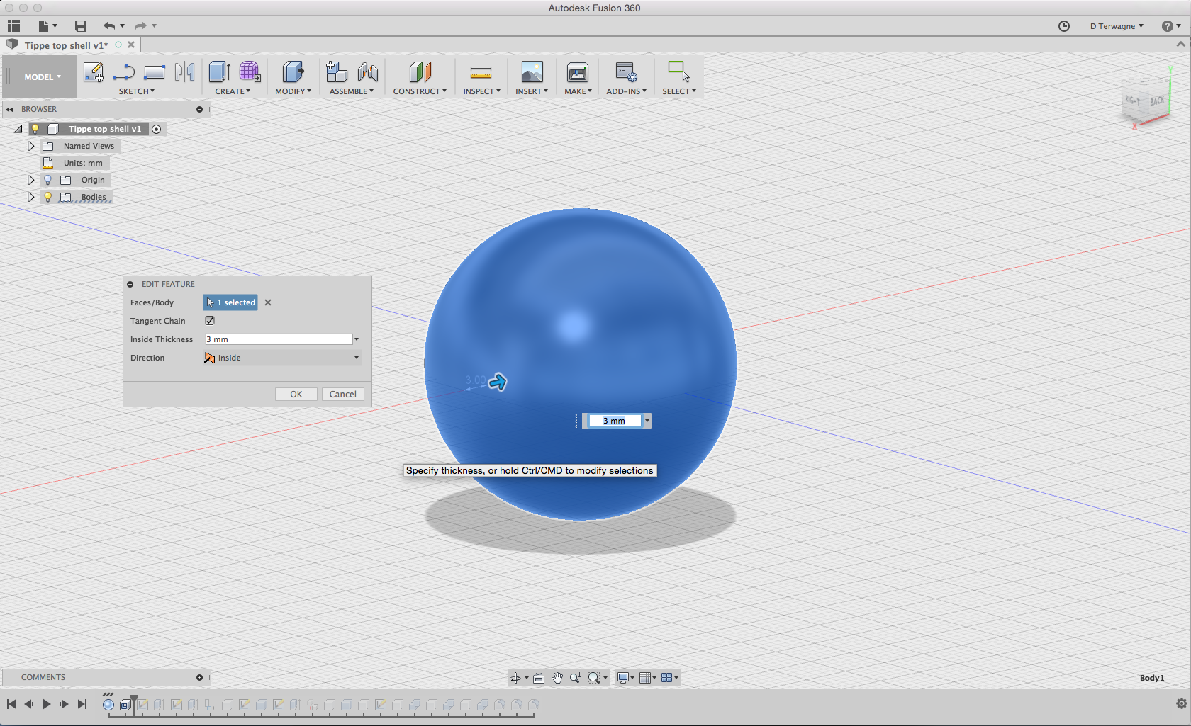
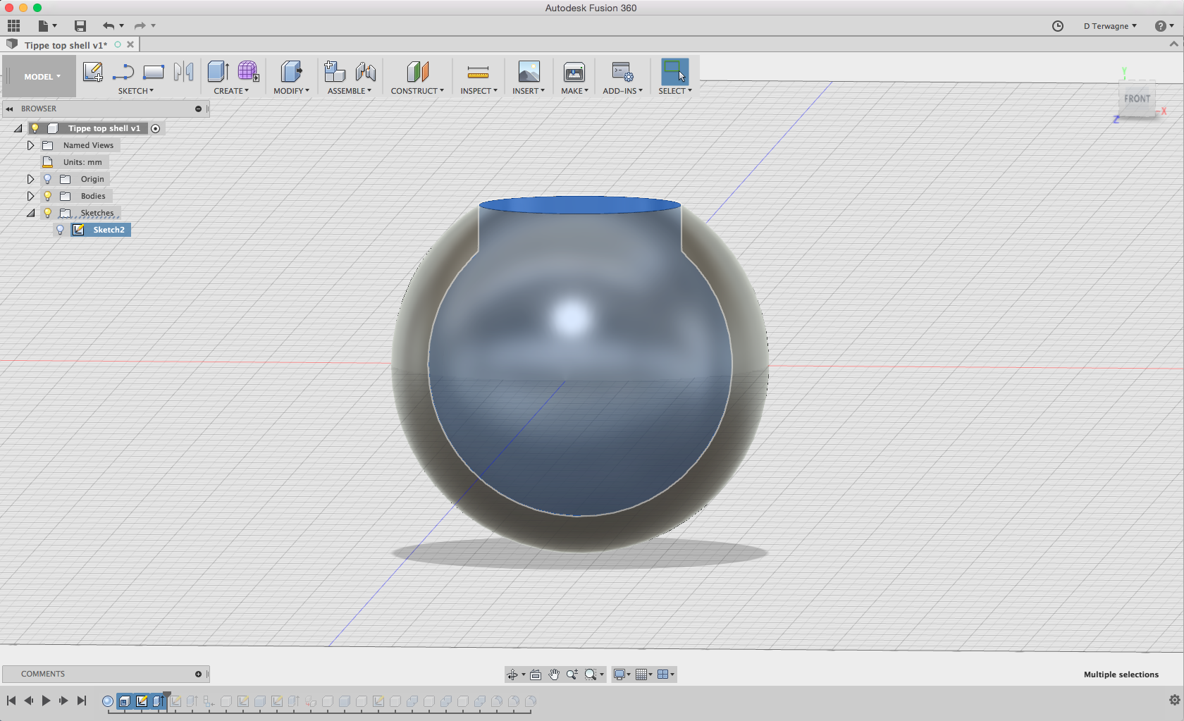
I then made a shell from the sphere.
I cut a cylinder through the shell.
Here is the side view with the inner shape that is revealed in blue.
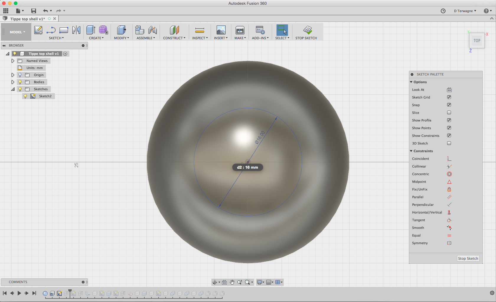
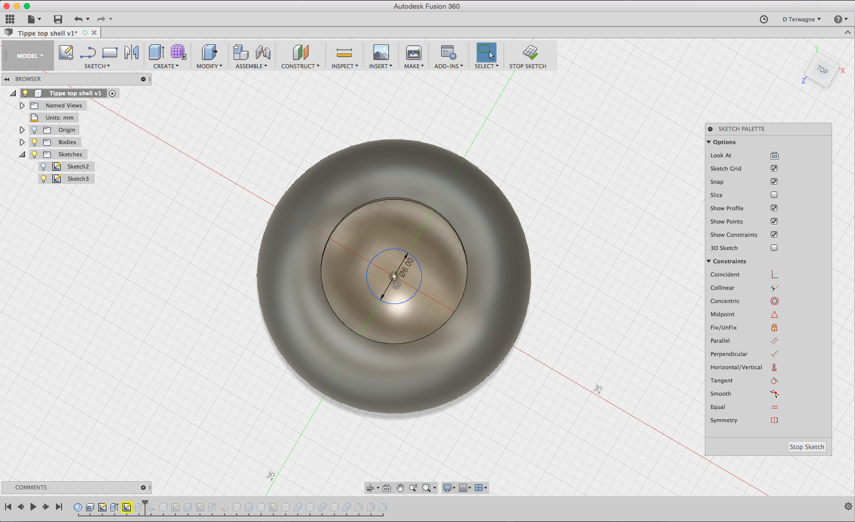
On a new schematic, I designed a disk.
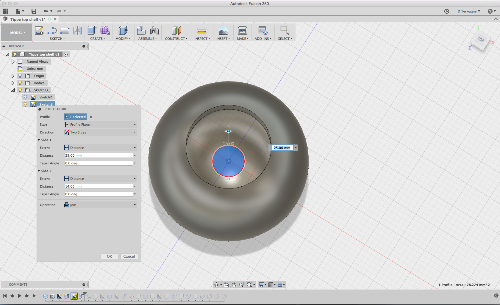
I extruded the disk, to make the handle of the tippe-top.
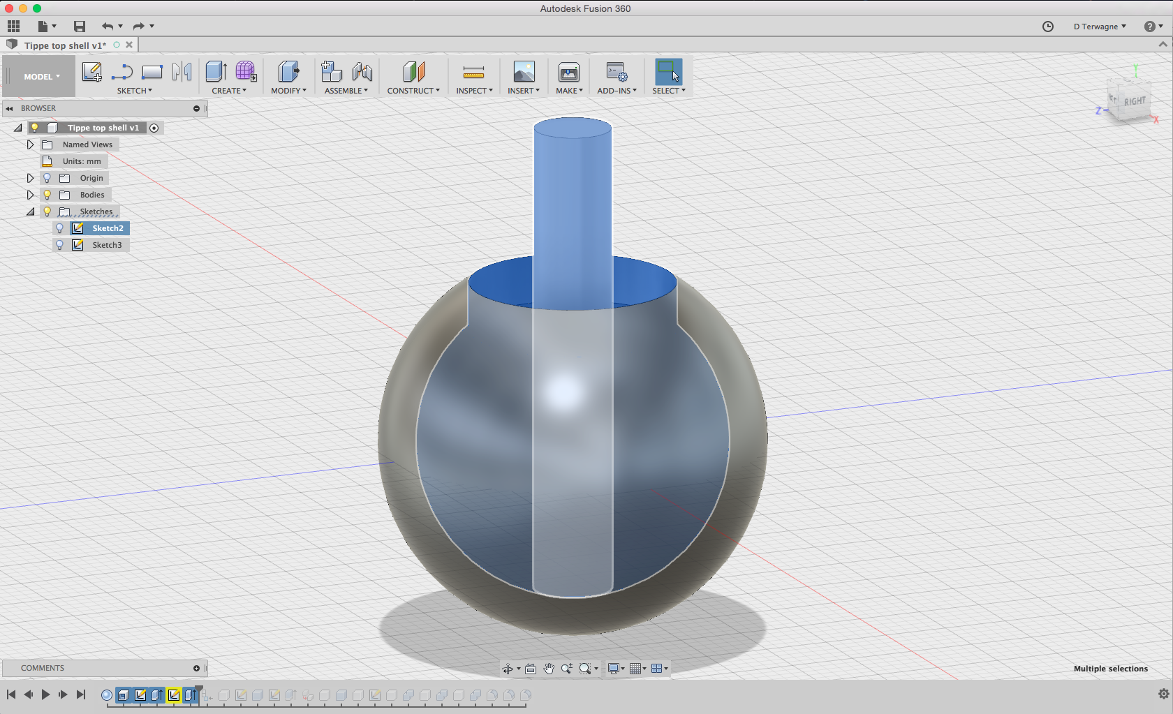
Here is the tippe-top with the extruded handle
I then made a filet on some parts of the design to finish the design
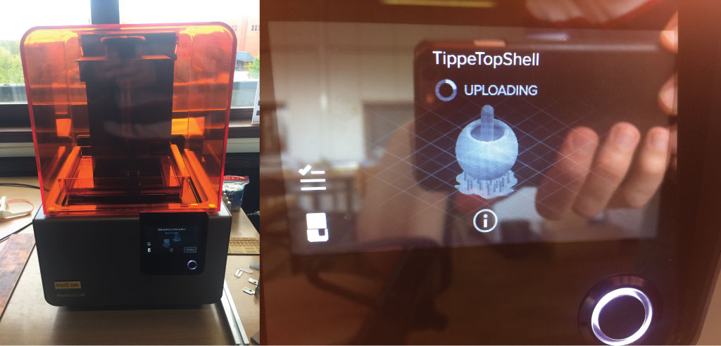
3D printing the tippe-top
I then exported a STL 3D file from Fusion 360 and 3D printed it on the Formlab printer using the same parameters as above (for the tugboat).
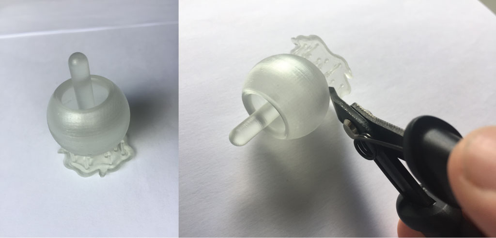
Here is the 3D printed part. We just need to remove the support poles by cutting and sand a little bit the bottom of the tippe-top to finish it and play with it.
Tippe-top hero shot
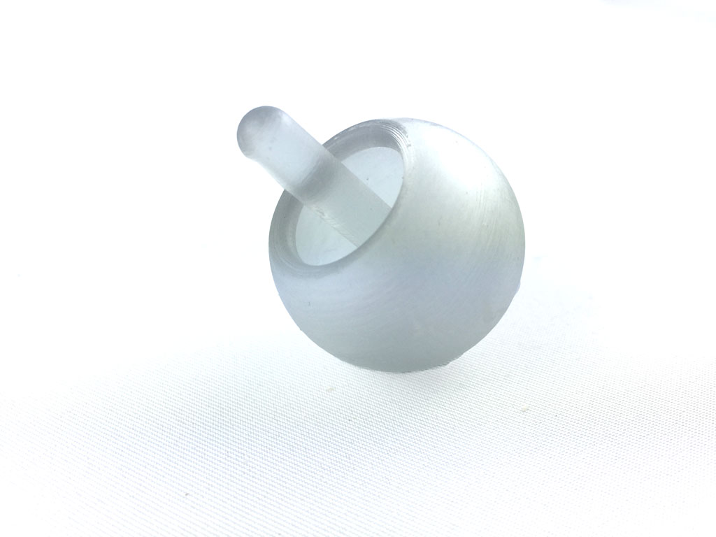
video
This tippe-top act like a simple spinning top and does not do the trick of the tippe-top which should flip over the small handle at some point. I guess this is due to the design of the tippe top. The center of mass should be higher so the top would be less stable and allow the flipping over. To be continued ...