Week 10 - Output devices
- Stepper motors from the MTM kit
- DRV8833 - Dual H-bridge motor driver
- A3967 Microstepping Driver with Translator
Softwares :
- Arduino IDE.
This week was the perfect week to learn about how to control stepper motors as we need them for the group project. I dug more deeper on how stepper motors work and how simple and double H-bridges are working. Also, I felt more comfortable with electronic component datasheets. I started to control the stepper motor with the board I designed in week 6 and I used some pre-written examples that I have adapted and changed along the week in order to control the stepper motor. What I've learned is to optimize how micro-controller pins are used and that you can assign them to multiple function (to allow the programing of the board and allow the program to work for example).
Preamble
For the group project, we decided to design and fabricate a drawing spider that uses two stepper motors. So, I took the opportunity this week to dive into the world of stepper motors control.
Controlling a stepper motor
Materials
To do that I used :
- A microcontroller board
- a dual H-bridge motor driver DRV8833
- a stepper motor from the MTM kit
Understanding the H bridge with DC motor control
Let start with a simple h-bridge to drive a DC motor. A H-bridge is a set of transistor that allow to control the flowing current in the motor as sketched below. When programming and controlling, we control the states of the different transistors. So we can let the current to flow in one direction or the other (forward motion or backward motion). We can also stop the motor by stopping the current to flow through the DC motor. The H-bridges act basically as amplifiers.

Dual H-bridges and stepper motors
To control a stepper motor, we need to control two sets of coils so we need 2 H-bridges. To do that we can use a chip like the one presented below the DRV8833. There is some logic integrated into that chip that allow the double H-bridge to function. With this dual h-bridge chip, we can either run 2 DC motors or 1 stepper motor.
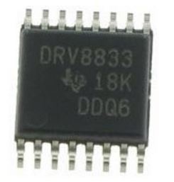
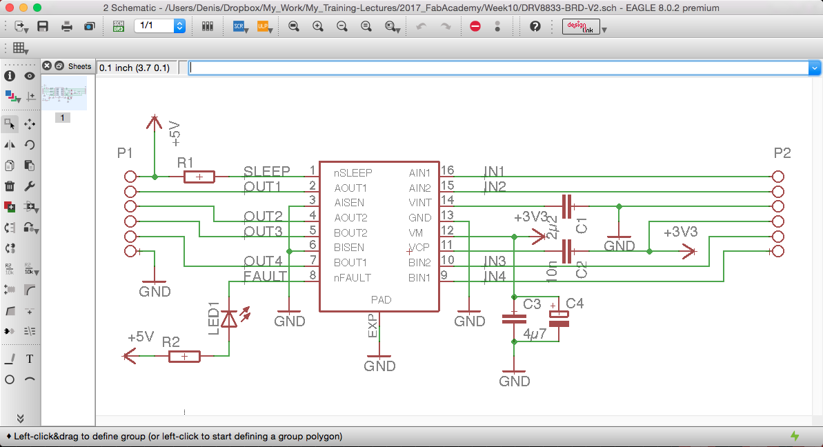
Here is the dual H-bridge motor driver DRV8833 that we used:
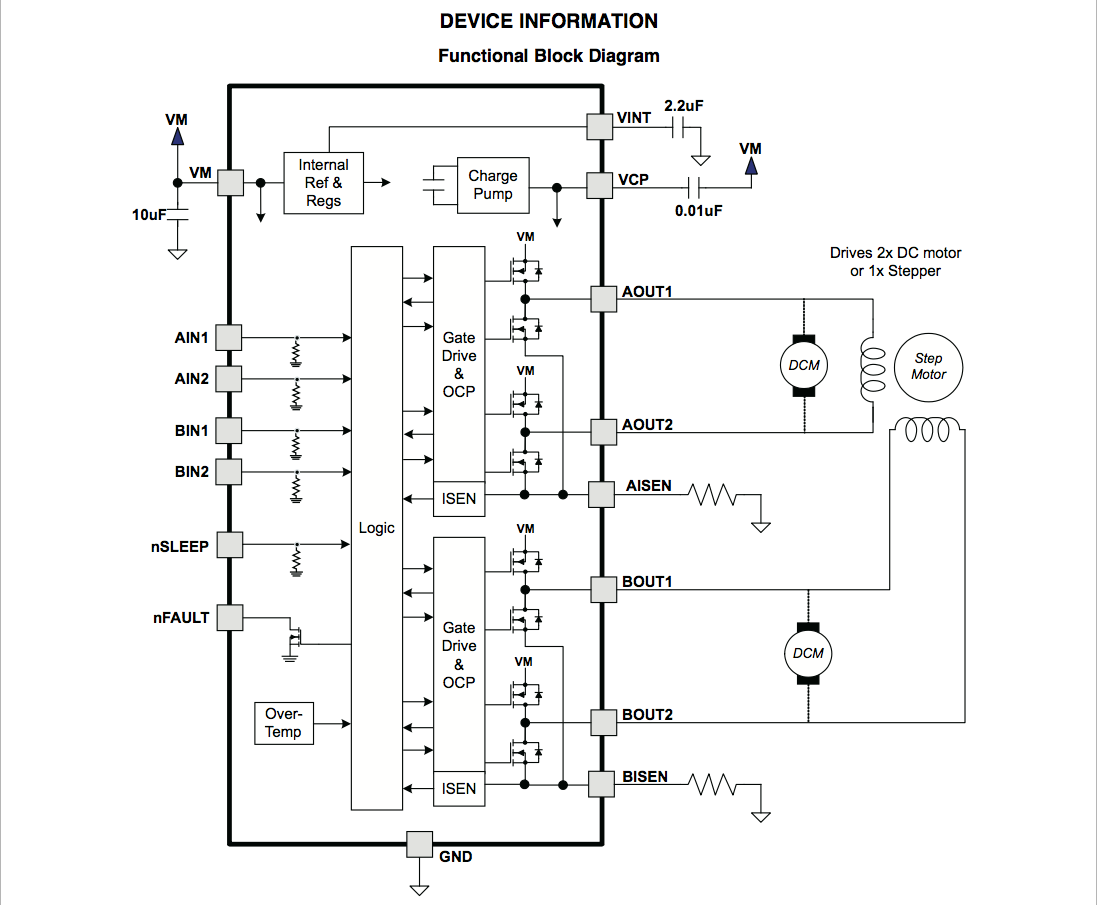
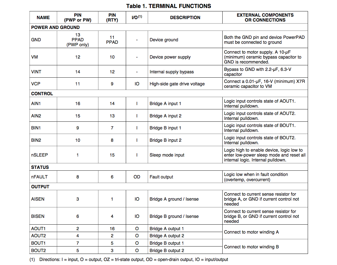
device information and terminal functions from the datasheet
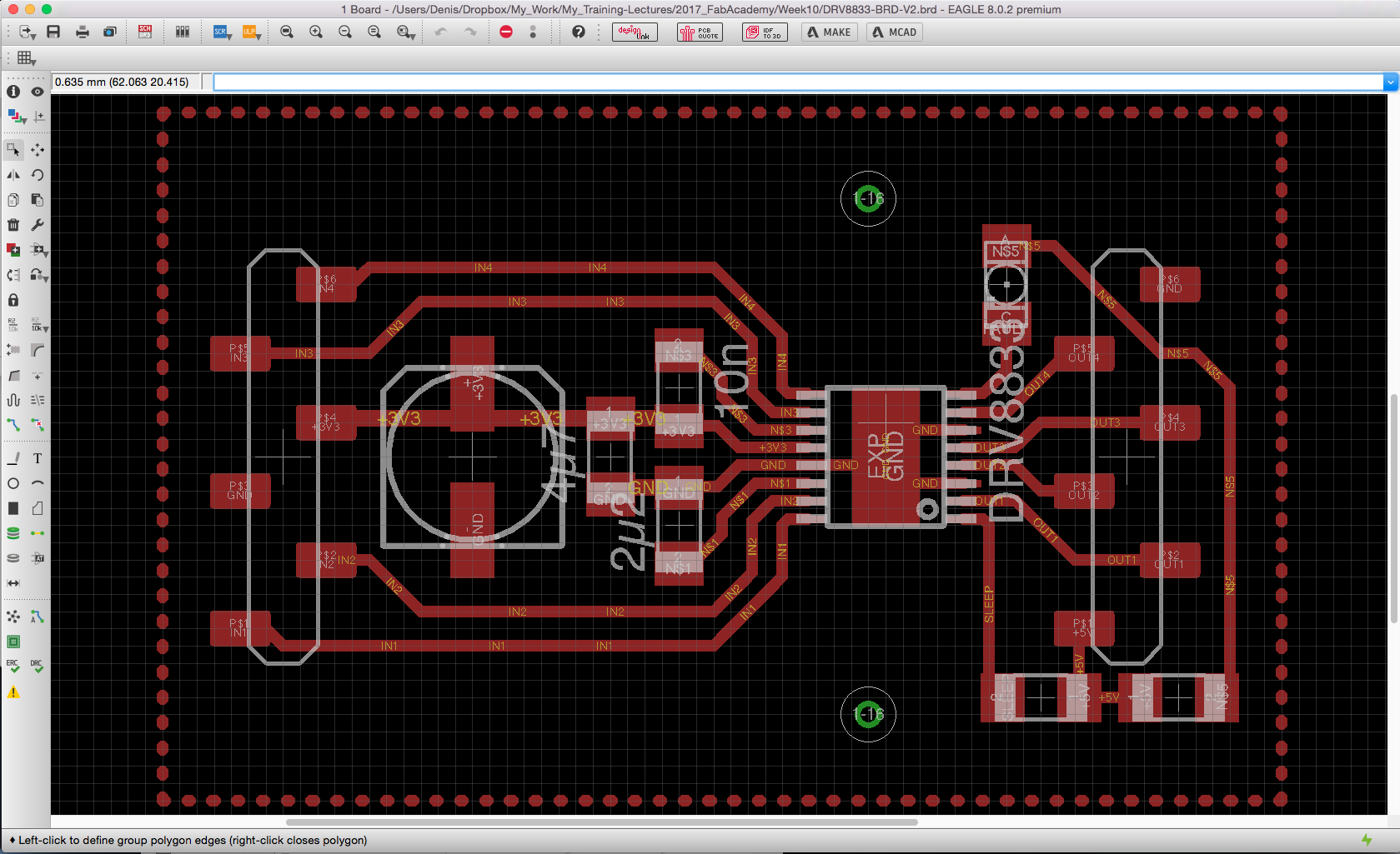
integrating the chip on a board
In the design of this board, we need to allow 4 input pins (IN1, IN2, IN3, IN4) that will control 4 output pins (OUT1, OUT2, OUT3, OUT4). We have to connect VM and GND pins to an external power supply to run the stepper motor. We can also connect the SLEEP pins to a high 5V voltage to enable the device (a low logic input put the device in a sleep mode).
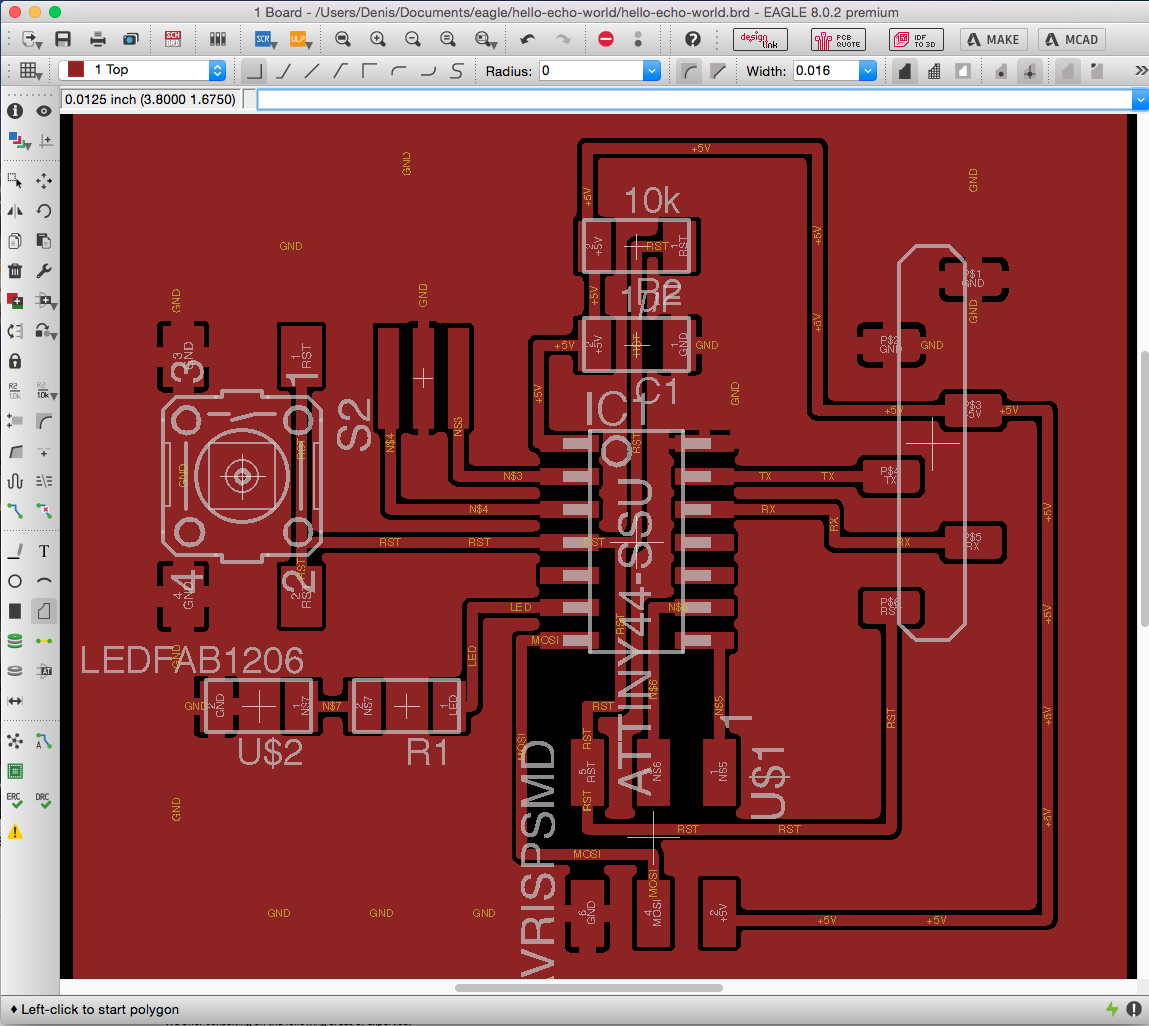
The microcontroller board
For this exercise, I chose to use the microcontroller board that we developed during week6. I need 4 output pins that I chose to be (N$5, N$6, RX, TX) which corresponds to microcontroller pins (8,9,12,13).
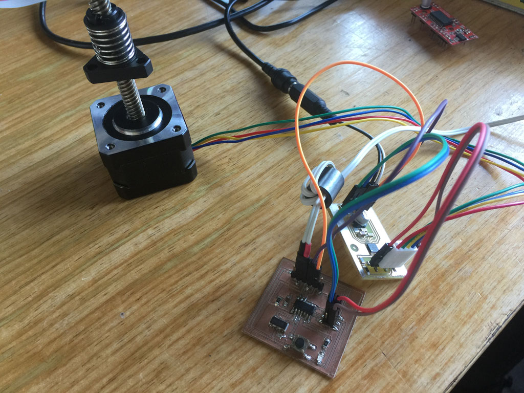
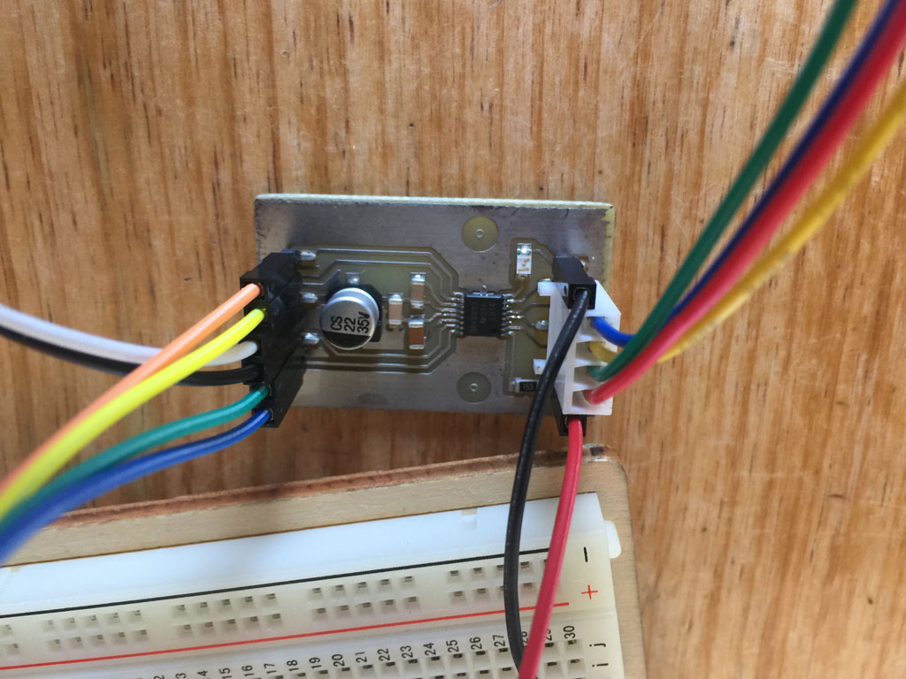
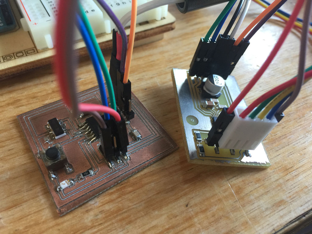
The microcontroller and the H-bridge
I have connected
- the 4 wires of the stepper motor to the driver (double H-bridge board).
- the board to the driver using 4 wires (green, blue,orange,violet) and the output pins (8,9,10,11).
- an external dc power supply (here 7.5V) to the ground pin and the 5V pin of the FTDI cable 6 header pins of the board (white cable) to power up the board.
- The board ground to the driver ground (brown wire).
- The sleep pin of the driver to 5V pin on the board (red wire).
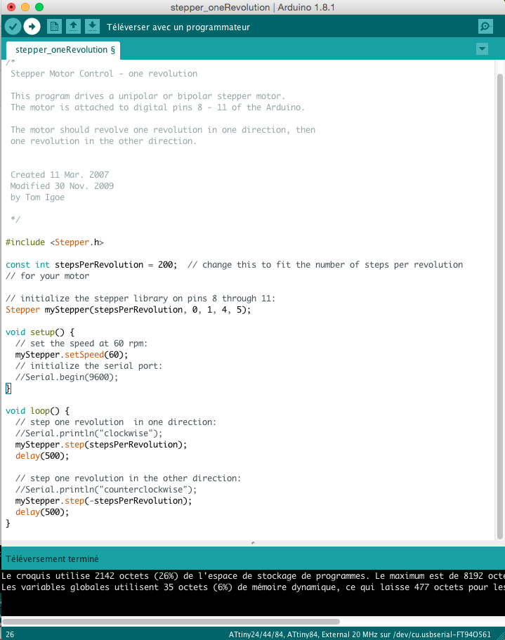
Programming the board
Here is the program I've used to control the stepper motor. When using the Arduino IDE, we need to translate the ATtiny84 pin numbers to the Arduino pin numbers. The ATtiny84 pins (8,9,12,13) correspond to the Arduino pins (0,1,4,5).
Digging in the Arduino libraries
To really understand what the function step(int) was doing, I searched for the Arduino libraries on my computer and found the code that is shown down here. We can clearly see in the comment section prior the code the different waveform that are sent through the 4 wires when the command is called.
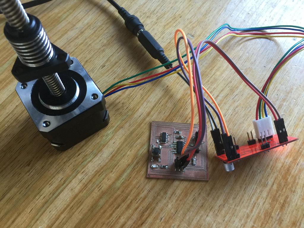
Video of the running board
Here is a video of the board running the program here above.
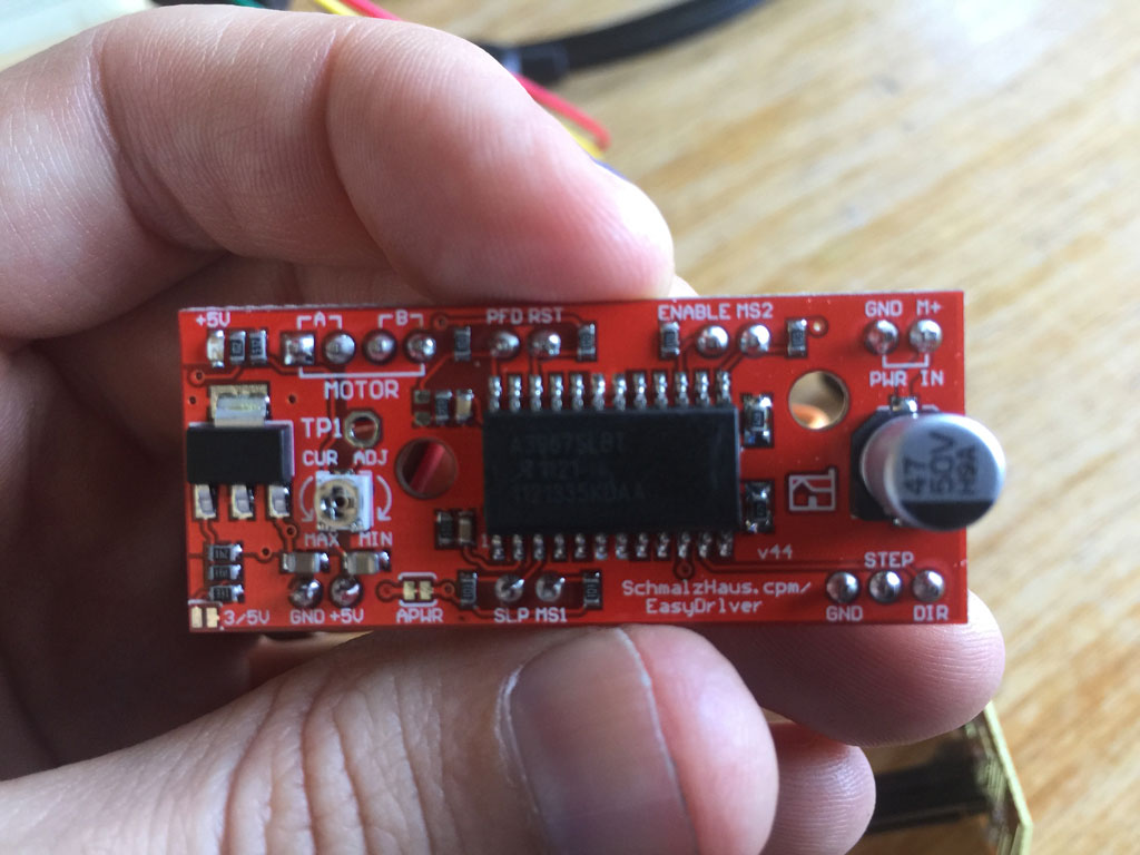
Testing a microstepper H-bridge driver
For this exercise, I wanted also to test another type of stepper motor driver that allow microsteps. It's a driver that has some logic encoded into it. An advantage of this driver is that the motor can be controlled using only 2 wires: one for the rotation diretion and the other one for the number of steps.
Inspecting the driver and reading the datasheet, we could understand the function of each pin.
Reading the stepper motor driver datasheet.
In this datasheet, it is important to check how the driver is meant to operate. The load supply is 30V so we can operate at maximum a 30V stepper motors. Logic supply voltage, it is the voltage required to power up the driver board.
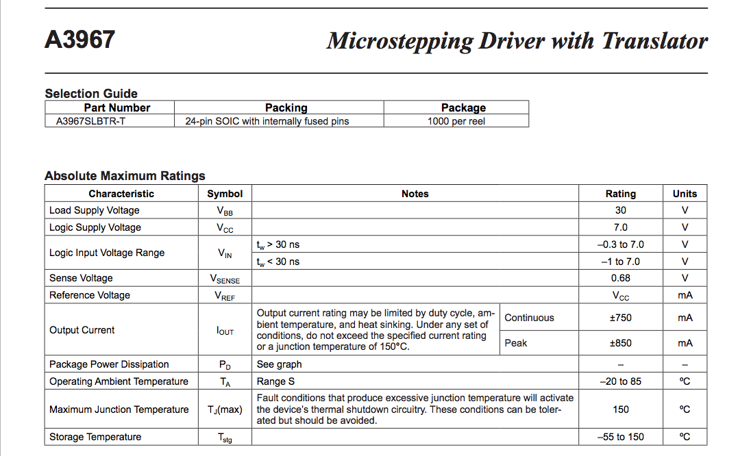
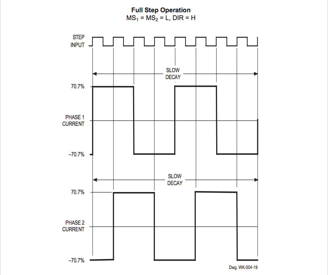
There are two logic pins (MS1 and MS2) that can be used to set the microstep resolution.

Here is an example. In full step operation, a 4 steps input will correspond to one motor step.
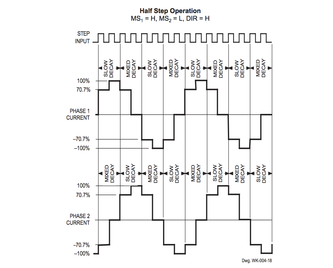
In half step operation. We need 8 logic steps to make a full motor step
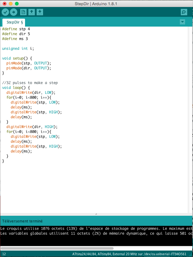
Programming and controlling the stepper motor for microstepping
Here is the program that I used to control the stepper motor.
Microstepping video
Here is a video of the motor that is doing microsteps.