Assignment
* Measure something: add a sensor to a microcontroller board that you have designed and read it.
Neil's class Summary
Design
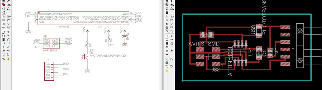
For this week assignment i chose to make a phototransistor board.
A phototransistor is a light-sensitive transistor that converts light into current, it changes its resistance based on the amount of light shining on it.
I based my board in
Neil's design.
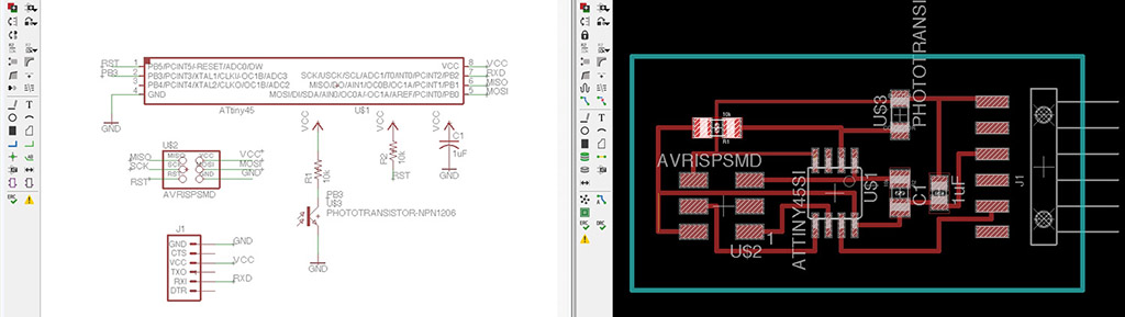 Here is the list of components.
Part Value                   Device                    Package  Description
C1   1uF                     C-USC0805                 C0805    CAPACITOR
J1                           ARDUINO_SERIAL_PROGRAMSMD 1X06-SMD FTDI connector footprints
R1   10k                     RESISTOR1206              1206     Resistor
R2   10k                     RESISTOR1206              1206     Resistor
U$1  ATTINY45SI              ATTINY45SI                SOIC8
U$2  AVRISPSMD               AVRISPSMD                 2X03SMD
U$3  PHOTOTRANSISTOR-NPN1206 PHOTOTRANSISTOR-NPN1206   OP1206
After running ERC and DRC tests, i exported the design directly to gCode by running a ULP script. For more information please follow
this link.
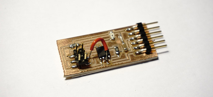
Milling and Soldering
The plate is very simple, the work of milling is short and the welding is not very complex.
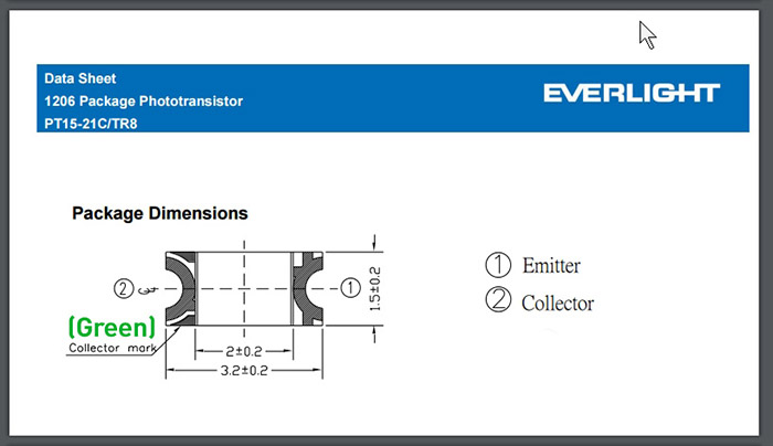
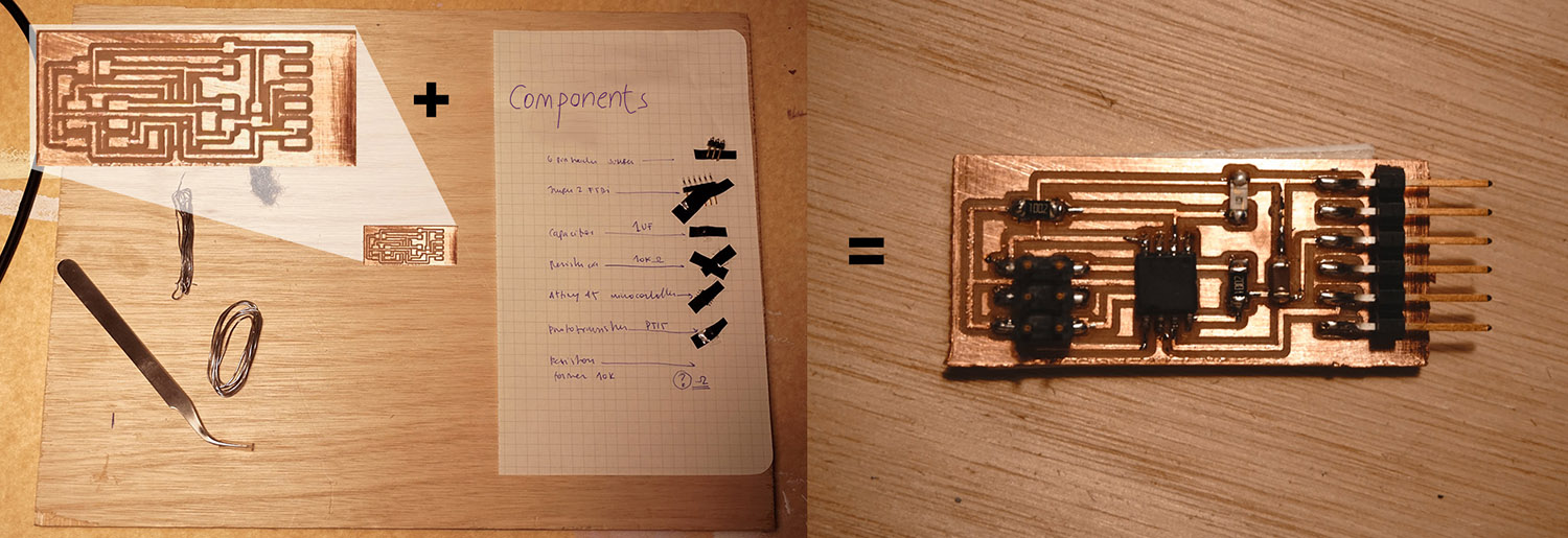 It was very useful to check in the
datasheet of the phototransistor the location of the emitter and the collector (green marks) so as to orient the component well at the time of welding.
It was very useful to check in the
datasheet of the phototransistor the location of the emitter and the collector (green marks) so as to orient the component well at the time of welding.
Programming: first try.
Following the steps of
Xavi Dominguez
(Fablab Barcelona). I plan to use
Neil's python code for visualizing and an upload a Arduino sketch for the serial communication between the board and the python code.
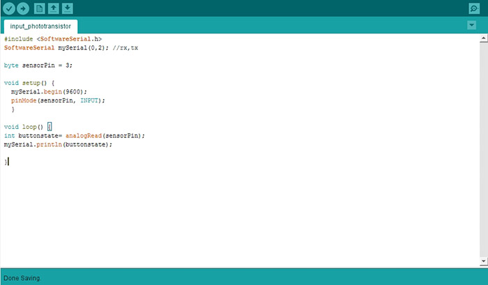 First, I tried to use my
FabtinyISP
but I can not make the Arduino IDE to recognize the device. It's strange because I've used it perfectly to program my
Hello board several times.
First, I tried to use my
FabtinyISP
but I can not make the Arduino IDE to recognize the device. It's strange because I've used it perfectly to program my
Hello board several times.
Then I tried to use an Arduino UNO configured as an ISP but I was not successful either.
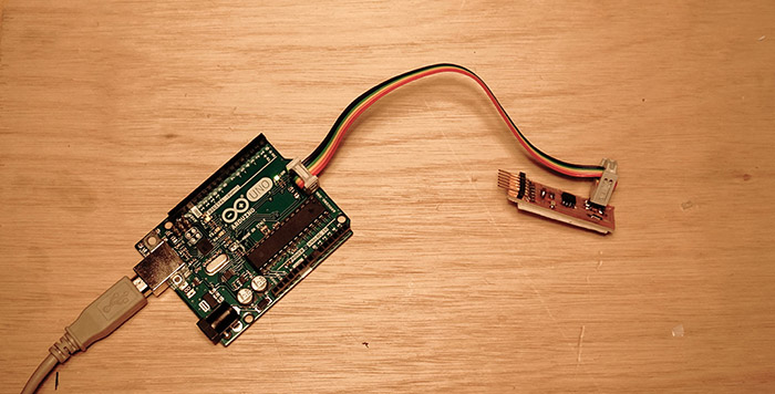
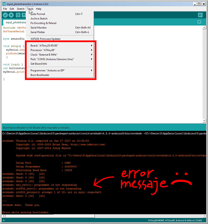 I checked the soldering, I rebooted the equipment, I changed the cables but I continue to receive the same error.
I will review the solderings again and try to program it directly from the terminal.
I checked the soldering, I rebooted the equipment, I changed the cables but I continue to receive the same error.
I will review the solderings again and try to program it directly from the terminal.
Programming: second try.
After checking the board solderings and connections to the pc several times, I decided to review the board design in Eagle and found a missing track due to poor track naming.
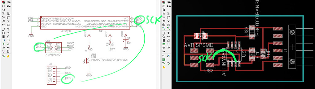 Here is the corrected design.
 And here the modified board with the missing track welded.
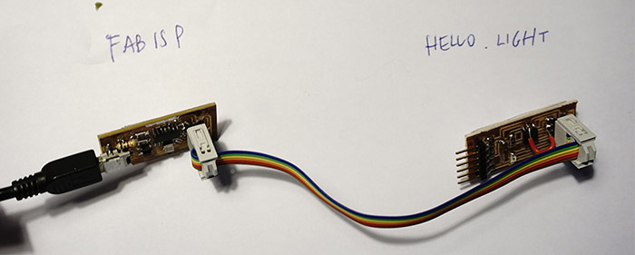
 To program the board I decided to use my FabISP USB connected to the PC and serially to the hello.light board.
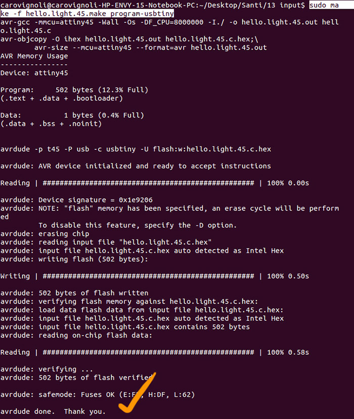
 And ran Neil's makefile through Ubuntu Terminal.
sudo make -f hello.light.45.make program-usbtiny
 Then I connected the hello.light board via FTDI cable to the PC and ran Neil's python script. You can check the device name from the terminal using the lsusb command. For me is /dev/ttyUSB0 .
python hello.light.45.py /dev/ttyUSB0
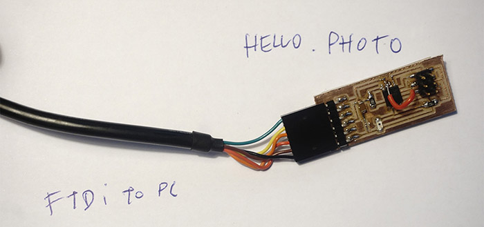
Here is the final result.
And here's a brief interpretation of Neil's Python code.
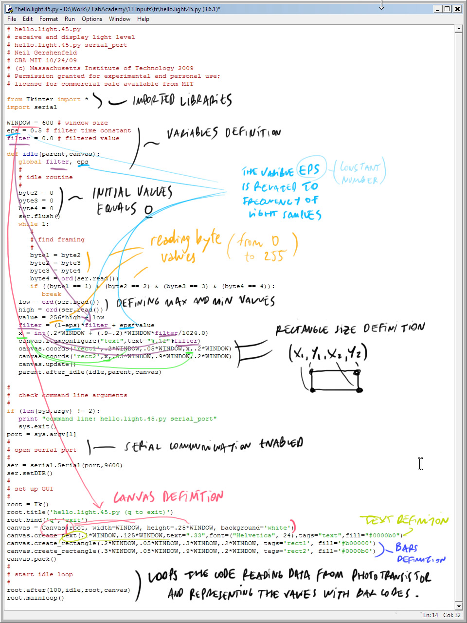 To visualize the readings of the phototransitor I directly ran the python code of Neil, I did not edit it. In the weekly assignment Interface and Application programming, with a little more time and programming experience, I played a bit with Neil's code to build and run my own Processing code.
Programming: third try.
In the first attempt i could'n program the microcontroller because of design problems during board's fabrication. In the second attempt, with the board working, and thanks to Neil codes, I managed to program the micro to transfer data via FTDI cable and using the python code to display the information of the phototransistor, now in this third approach, with a little more programming experience in Arduino IDE, I made a code that reads the value of the phototransistor, applies a filter and returns the light level as it is darker or brighter through serial monitor.
#include >SoftwareSerial.h>
#define RX 0
#define TX 2
SoftwareSerial mySerial(RX, TX);

// Value of low pass filter:
float filterValuePot = 0.3;
float filterValueLight = 0.3;

int photopin = A3;

int valuePhoto;

void setup() {
  mySerial.begin(9600);
  pinMode(valuePhoto, INPUT);
}

void loop() {

  int newValuePhoto = analogRead(photopin);   // reads the value of the phototransistor (value between 0 (+light) and 1023 (-light))
  valuePhoto = filterValueLight *  newValuePhoto + (1.0 - filterValueLight) * valuePhoto; //  phototransistor filtered value
  mySerial.print(valuePhoto);

  if (valuePhoto < 100) {
    mySerial.println(" - Very bright");
  } else if (valuePhoto < 300) {
    mySerial.println(" - Bright");
  } else if (valuePhoto < 600) {
    mySerial.println(" - Light");
  } else if (valuePhoto < 900) {
    mySerial.println(" - Dark");
  } else {
    mySerial.println(" - Very Dark");
  }
  delay(1000);
}
I used Arduino as ISP
to burn the program on the micro following this tutorial
Download the files.