Assignment
* Add an output device to a microcontroller board you've designed and program it to do something.
Neil's class Summary
Design
Thinking about some ideas that I have had for my final project I decided to design a circuit that can operate a small solenoid as output device (Thank you Alvaro for lending me that gadget). This smaller solenoid is designed to work directly with 5V. Here is the datasheet.
The first thing to do the design was to look for some examples of similar and found a pair very useful:
here and here.
These are the components to be used:
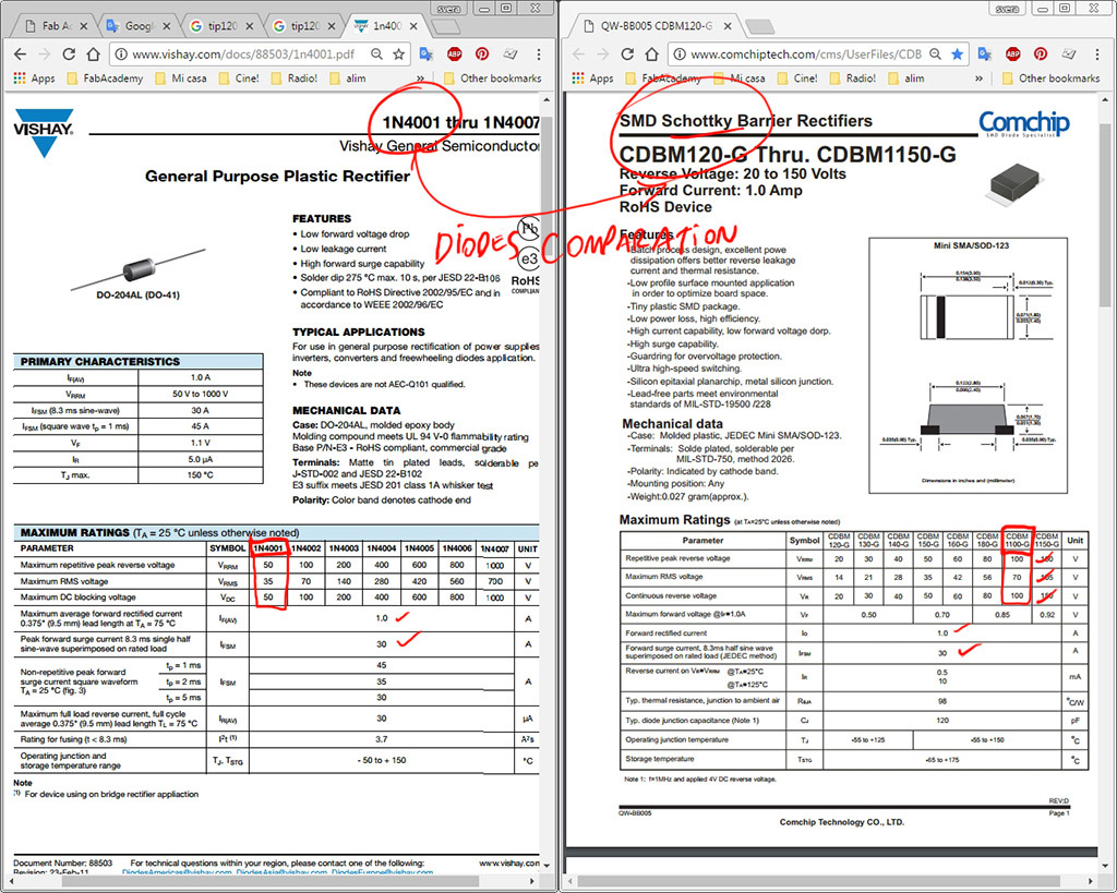
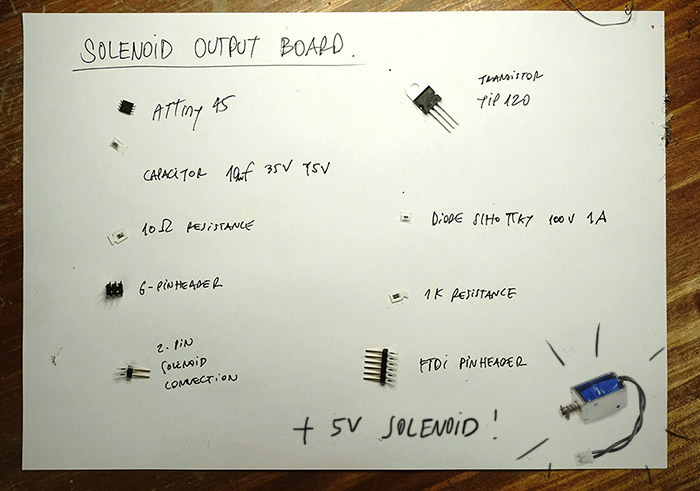 I used a TIP120 transistor and a Schottky 1A 50V diode, I verified that this diode had similar characteristics to the 1N4001 diode, frecuently used in these kind of cases.
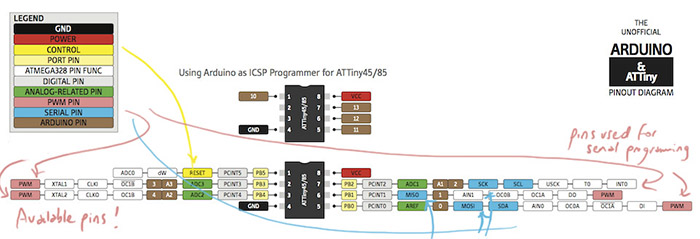
 Since the solenoids, as well as the motors, can be operated at different intensity, I must provide an output pin with PWM mode timer function on the ATTiny 45 microprocessor.
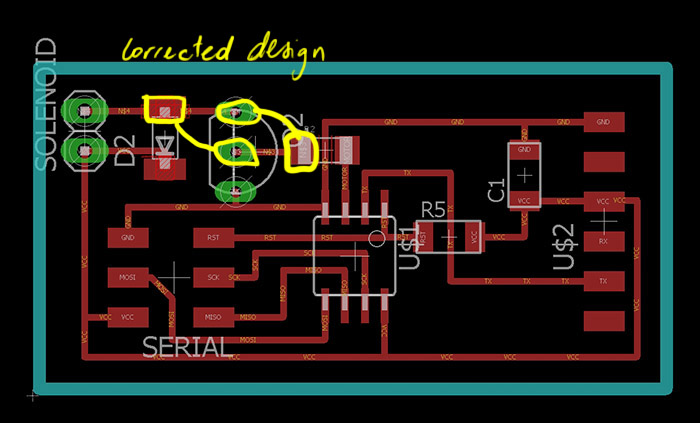
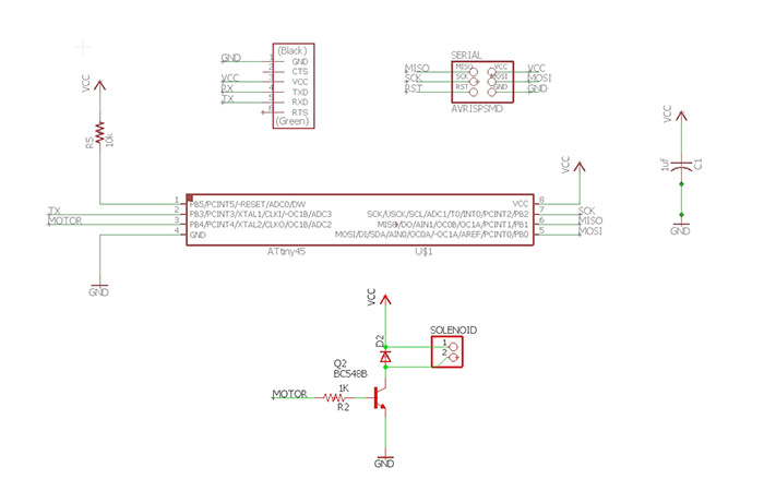
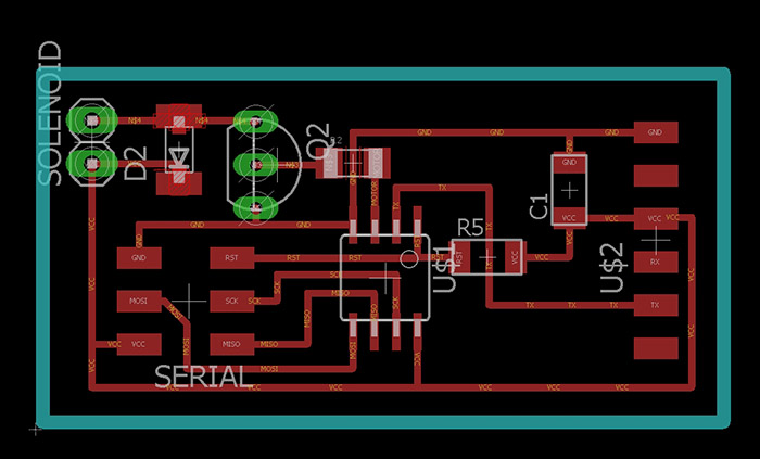
 Here is the final design solution in Autodesk Eagle.
Assembly
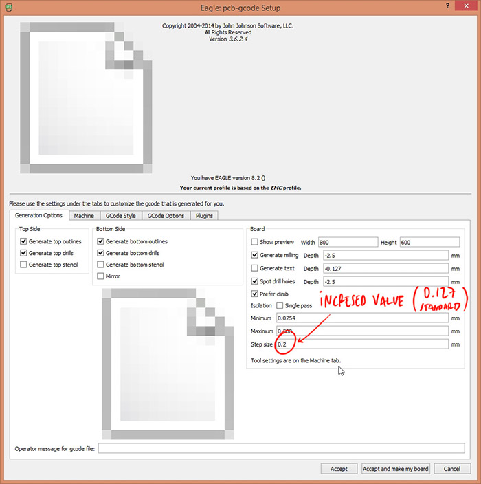
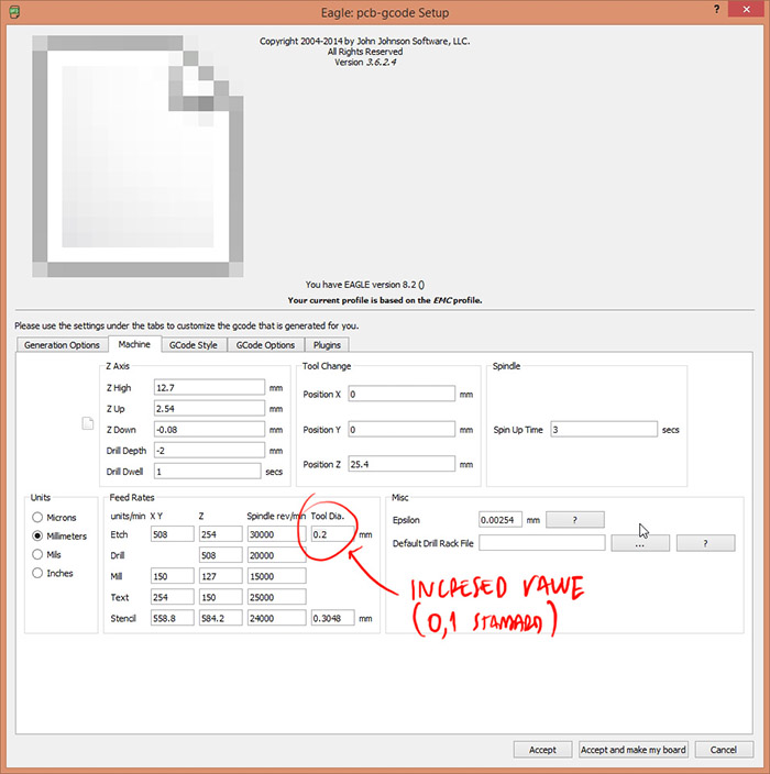
After exporting the Eagle files to standard G-code (tap files) following these instructions and using the following ULP configuration:
 milled the board with our local Gava Milling Machine. Here is the soldering process and a short video of the result.
Programming
For this week assignment programming, i decided to test programming m my board using an Arduino UNO as an ISP. The steps to follow are:
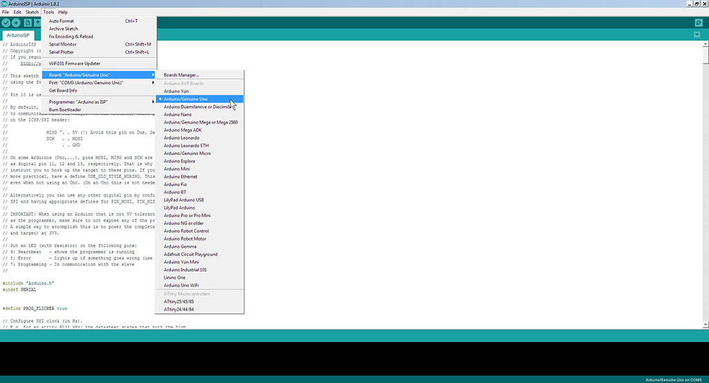
1. Connect the Arduino UNO via USB, open Arduino IDE, load the "Arduino as ISP" sketch (under File / Examples) and then in Tools set the board as "Arduino/Genuino UNO" and choose the COM port to which it is connected.
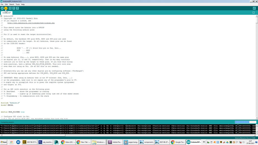
 2. Verify and Upload the sketch to the Arduino board.
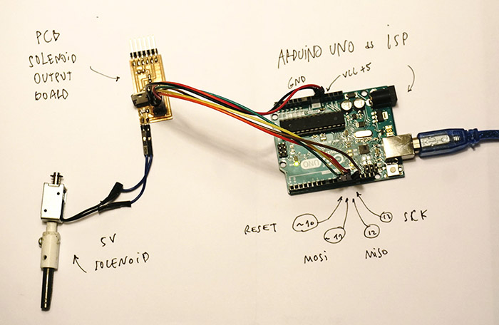
 3. Then connect the solenoid output board to the Arduino.
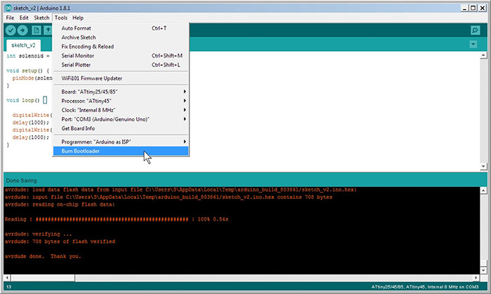
 4. Open the sketch with the program that will be uploaded to Attiny 45, then in Tools choose "ATtiny25/45/85" as Board, "ATtiny45" as Processor, Clock: "Internal 16Mhz", the COM port (same as used previously) and "Arduino as ISP" as programmer, finally run the bootloader.
 5. Now Verify and Upload the sketch to the ATiny45 board.
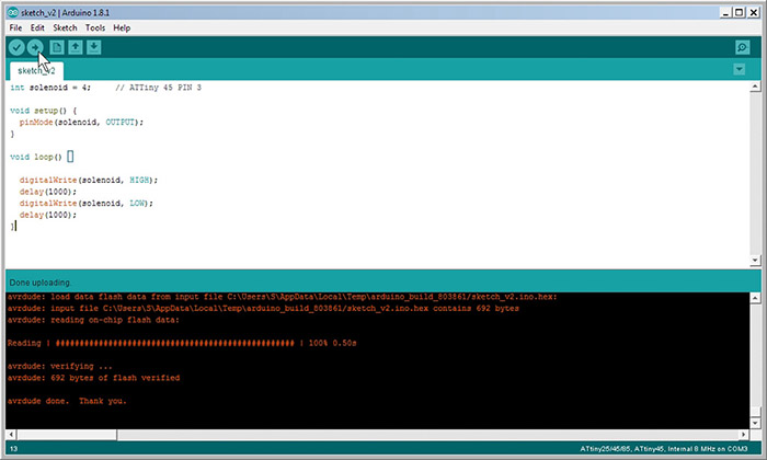 Here is the simple piece of code i used:
int solenoid = A2;     // ATTiny 45 PIN 3

void setup() {
  pinMode(solenoid, OUTPUT);
}

void loop() {
  analogWrite(solenoid, 127); //analogWrite() is on a scale of 0 to 255, analogWrite(255) requests a 100% duty cycle (always on), and analogWrite(127) is a 50% duty cycle (on half the time)
  delay(1000);
  digitalWrite(solenoid, LOW);
  delay(1000);
}
I have been reading some information on how to use the variation of power (PWM) to test it in the solenoid and thus avoid possible increase of temperature in the device. Using analogWrite an analog value can be written to a particular pin. I considered 127 as the initial test value.
Even though the programming was successful, I still have not been able to run the circuit. I will recheck the connections and components used.
Download the files.
Update
After reviewing the design I discovered an error in the use of the components. In Eagle's schematic design I used a BC548 transistor and at the time of welding I switched to a TIP 120 because of its better emitting capacity. At that moment I forgot to compare their respective pins.
![]() And there I think the problem is. Bridging the circuit in the following way would make it work.
And there I think the problem is. Bridging the circuit in the following way would make it work.