
Assignment objectives:
* Make an in-circuit programmer by milling the PCB.
Neil's class Summary
Milling: first approach.
After our
weekly class on electronic production with Neil
, we were led by Carolina, our local instructor, to the basic understanding of circuits: how do they work, its components, the milling options for boards and the final programming for the FabISP.
At the local FabLab we don´t count with the Rolland mill equipment suggested as default tool for milling the PCB. Instead, we were introduced to our local handmade milling machine, named by our team as "Gava Milling" in homage to Martin Gava, its creator, our skillful autodidact electronics maker at
Sinergia Tech.
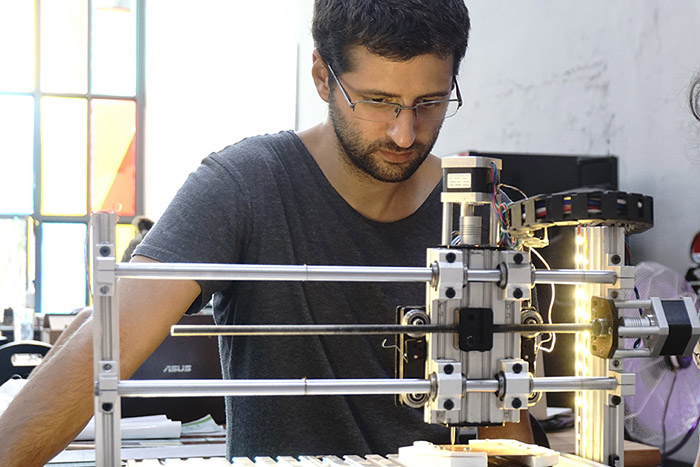 Martin told us about the fabrication process, its components and its capacities.
Although the machine is still at testing process, we learned how to work with it using
CNC-GCode-Controller
java application. It runs under commandline in universal GCode language.
After tested some G and M codes (
here is a complete list of codes
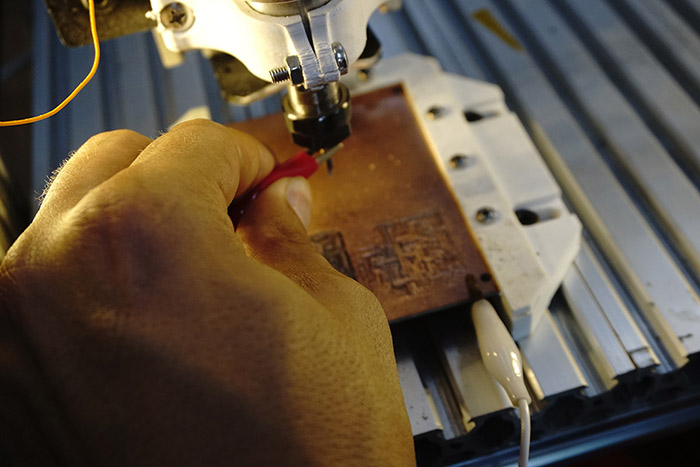
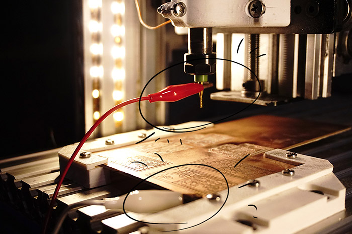
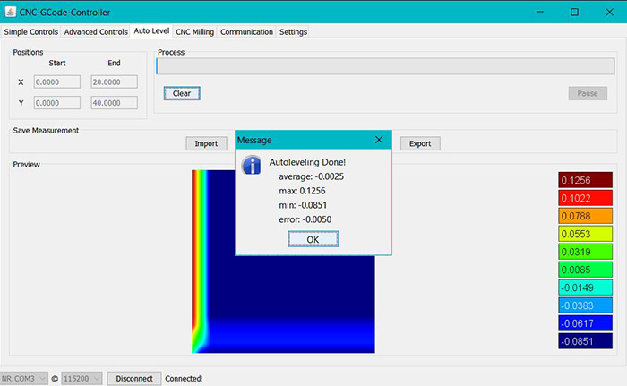
) we learned how works the leveling process: the white switch grabs the PCB board, the red one grabs the mill and the circuit closes before starting the process.
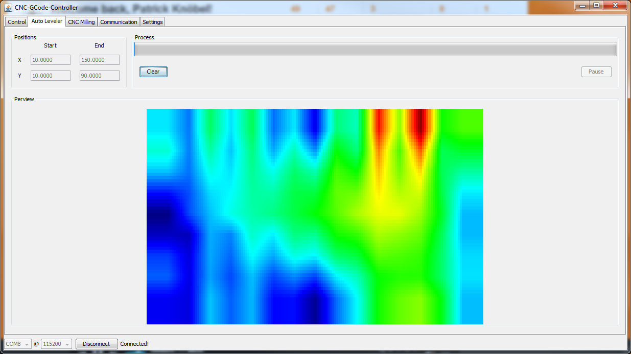
 The application allows to set a rectangular grid of measure points over the board in order to have full control over the milling height, the result is a gradient map showing the differents heights.
 The testings in the new milling machine are supposed to be finished in the next days so we will be using it along the rest of the course, for now we will look for an alternative option to mill the FabISP.
Milling: second approach.
We were invited to visit
Vacodir
in Montevideo city, a technologic wholesaler where
Marcelo Berruti
(our Blender specialist) is working, in order to test the new ZMorph equipment and mill our FabISP PCB board.
You can check the specs of the multi-tool printer
here
.
It has tremendous flexibility for desktop users, it allows to 3d print, mill, cut and engrave by simply switching printer heads, however it seems to have a fairly complicated manual leveling procedure.
Zmorph printer is driven by
Voxelizer
application. Voxelizer only allows to import two type file extensions: gcode and dxf, so we rasterize the PNG file of the
generic ISP solution
and we also include a cool V-sign suggested by Mercedes.
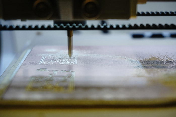
After configuring the position of the pcb board into the printer's table, we set the material thickness, cutting depth and pointer offset.
 Let´s mill!
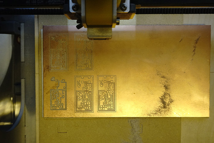
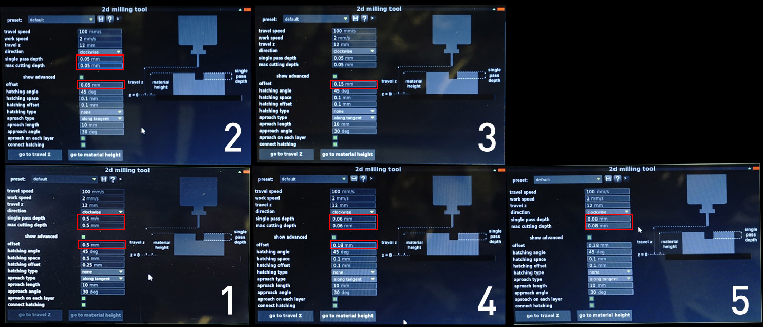
 We milled a total of five different tests.
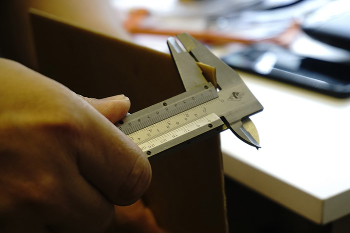
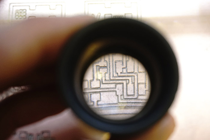
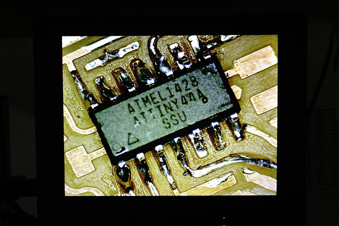
 It is very useful to use a lens for a detailed view of the quality in the traces of the board.
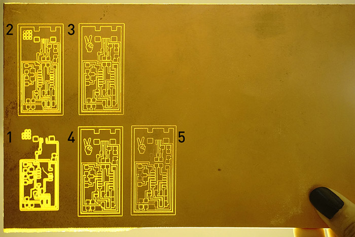
 We also check the milling tests putting some backlighting.
 Here are the parameters we used.
 Zmorph did its part but soldering would have been extremelly difficult because the milled offset wasn't really enought
Gava milling machine: step-by-step usage.
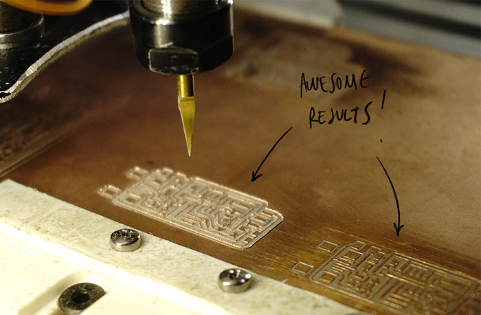
Finally we were able to mill the boards in our local machine built by Martin Gava.
This machine works with universal g-code so fab-modules was not used or needed here. We decided to use the
FabOptimus design, created by
Ali Shtarbanov, for our personal ISP. We downloaded the
design files in
Autodesk Eagle
formats (.sch, .brd) and exported to g-code following these instructions.
We developed a brief manual for the use of the machine. These are the steps to follow:
1. Open
CNC-GCode-Controller
and go to the "Settings" palette, "Import" button. Download and select
CNC settings.ois.
2. With the milling machine powered off, connect the USB cable to your PC. In CNC-GCode-Controller select the port (COM), the connection speed (115200 baud) and then press "Connect".
3. Turn on the milling machine.
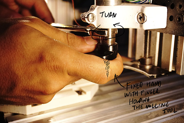
4. Changing the endmill. First, from the "Simple Controls" pallete move the tool to a convenient location for manipulation, then loosen the splindle by using the two keys and avoiding at all times the endmill from fall. To place the new milling tool, take the same precautions.
5. Put the copper laminated board in the machine.
6. Setting x and y to zero. Using "Simple Controls" palette move the tool to the location of the board that we want to derermine as the origin of x and y. Then under "Communication" palette run the command:
G92 X0 Y0and use
M114
To verify the relative position of the pointer (should return X = 0.0000, Y = 0.0000).
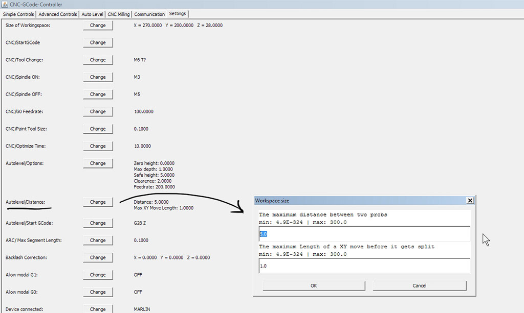
7. Setting z to zero. In the "Auto Level" palette, we introduce the dimensions of our pcb board. ("Start" X = 0, Y = 0, "End" X = distance, Y = distance) We can vary the distance between points to be relieved from the Settings palette, "Autolevel" / "Distance", "The maximum distance between two probs".
 Now put the electrodes, one on the copper laminated board and the other in the endmill.
 Now press "Start" button. Wait until the autolevel process is complete. Then remove the electrodes by avoiding touching other metal surfaces and making sure they keep securely attached to plastic surfaces.
CNC-GCode-Controller should return something like this:
IMPORTANT! During the milling process the PC can not be disconnected from the USB cable and can not be turned off or into sleep (doble check your PC Power Options before start).
8. For the milling the board, we go to the "CNC Milling" palette, then "Load File" (etch.tap files for milling traces, mill.tap files for exterior cuts and drill.tap files for drills), then "Optimize". By selecting differents values from the "Layers" list it is possible to previsualize the job (positive values correspond to movements above de plate and negative values to below ones). By clicking on "Mill" the milling process begins.
 And here is the result.
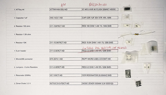
Assembly
After checking the list of materials to be used we found that we did not have surface mount 1.5 k resistances, so we decided to use a thru-hole component available in the local market.
 At the time when we were soldering the PCB board, we had the honor of having the help, knowledge and passion of
Alvaro Cassinelli
, our wise, visionary and experienced technology guru. He introduced us to a deep view of the circuits. We observed in detail the quality of the welds in the Attiny44. Thanks for the journey Alvaro!
At the time when we were soldering the PCB board, we had the honor of having the help, knowledge and passion of
Alvaro Cassinelli
, our wise, visionary and experienced technology guru. He introduced us to a deep view of the circuits. We observed in detail the quality of the welds in the Attiny44. Thanks for the journey Alvaro!
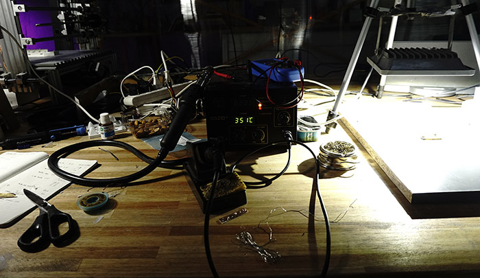
 At the time of welding remember to do it from the inside out, starting with the larger components towards the smaller ones, checking, as you progress, that the connections work properly. The recommended soldering temperature is 350 °C.
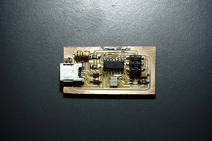
 The solder went fine and here is the pcb board result.
Programming
Programming was the most difficult task. As we count with a USBasp programmer, first thing to do is download the drivers for Windows 7 from this site.
Secondly, install the necessary software for AVR programming. I was not very lucky with WinAVR or Cygwin for Windows 7. Then i tried to use Arduino as ISP following this and this tutorial but didn't work neither, so I directly used avrdude and GCC software under Ubuntu following this tutorial. These are the steps:
Open Terminal and type:
sudo apt-get install flex byacc bison gcc libusb-dev avrdude
Then type:
sudo apt-get install gcc-avr
- type "y" when asked to do so by your system
Then type:
sudo apt-get install avr-libc
Then type (may already be installed):
sudo apt-get install libc6-dev
Download and unzip the Firmware:
Move to the desktop
cd ~/Desktop
Download the firmware from the Fab Academy Electronics Production page.
wget http://academy.cba.mit.edu/classes/embedded_programming/firmware.zip
Unzip the firmware
unzip firmware.zip
Then made the connections for program the FabISP
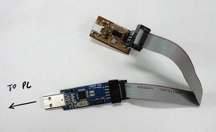 And edited the Makefile located in the firmware directory previously downloaded, by changing the programmer name in line #17 to USBasp in my case.
AVRDUDE = avrdude -c USBasp -P usb -p attiny44
Back to firmware folder location in Ubuntu's Terminal type:
sudo make clean
Wait for the response and then type:
sudp make hex
Wait for the response and then type:
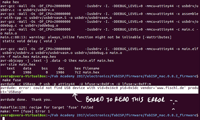
sudo make fuse
At this point I got several error messages similar to this one:
 After running several "Smoke tests" and running the process on another PC of our local FabLab and the programming was successful!
 You can check its usage in Input devices week 13 assignment.