Procedure:
0. Assignment
1. What I Need
2. What I Will Do
3. Board Designs (sketch + board)
4. My Final Boards
5. How Dows The USART work?
6. Programming: Strategy
7. Programming: Code
8. Problems Accounted
9. Download Files
0. Assignment
Design and build a wired &/or wireless network connecting at least two processors
Learning Outcomes:
Demonstrate workflows used in network design and construction.
Implement and interpret networking protocols
Have you...
...described your design and fabrication process using words/images/screenshots?
...explained the programming process/es you used?
...outlined problems and how you fixed them?
...included original design files and code?
The ouput board will have more modification, as now I will be using a Nema 14
Stepper Motor which will need more volts to work.
This means:
-using an external supply VCC (12 volts)
-adding a component: regulator ZLDO1117
-adding a 2x2 SMD Pins to connect the board with Serial Communication
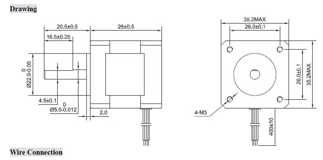
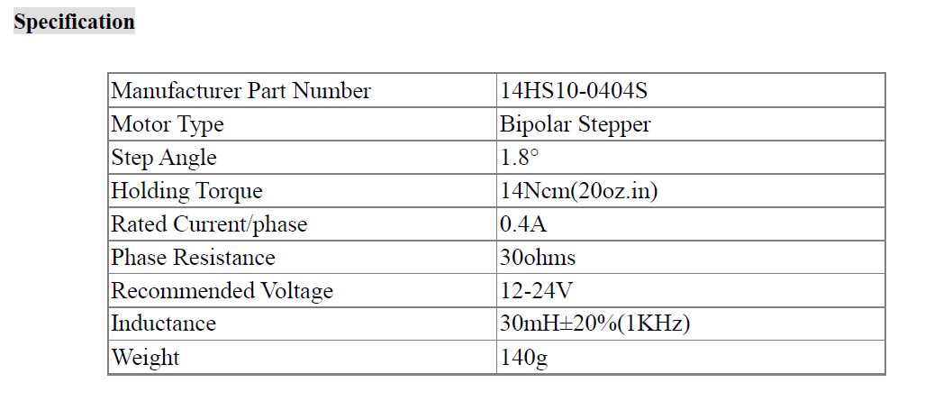
Nema 14 Stepper Motor
The motor I will be using is 'Nema 14 - Stepper Motor':
It is a hybrid bipolar Nema 14 stepper motor:
-1.8 degrees step angle (200 steps per revolution).
-Each phase draws 0.4 A at 12 Volts, allowing for a holding torque of 14Ncm (20oz.in).
ZETEX Regulator - ZLDO1117
Maximum Current Capability: 1A
Operating Voltage: 1.2 V - 18 V.
2. What I Will Do
For this week's assignment, I will build a wired network with serial communication
with two slave boards + the computer. Looking forward to my final project, I need
this type of communication to connect my input devices at the base of
the lamp with the stepper motor at one side.
Therefore, theses boards are based on the input and output boards I have designed
weeks ago, having small changes to satisfy the needs of my final project.
My strategy is to speak to the boards and activate the one that I want. I will be
doing this by using numbers and calling each one of them.
Once I succeed, I will go one step forward, while developing my project, to
activate the stepper motor to move one direction or another depending on the
sonars.
Let's go for it!
3. Board Designs (sketch + board)
Based on my last two boards (input and output board), I have created these new
boards for my final project including Serial Communication between
boards possible.
Going back:
Boards
Input
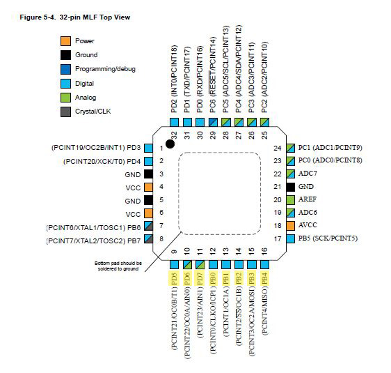
For my input board, I needed to add a second sonar to my board. As before I was
using the ATmega 168 mcu, I had a look to which pins I could use: I am already
using PB1, PB2, PB3 and PB4, plus now I will be using PD5, PD6, PD7,
PB0.
Atmega 168 Data Sheet:
This will be added next to the previous 1x04 long pad of the input board.
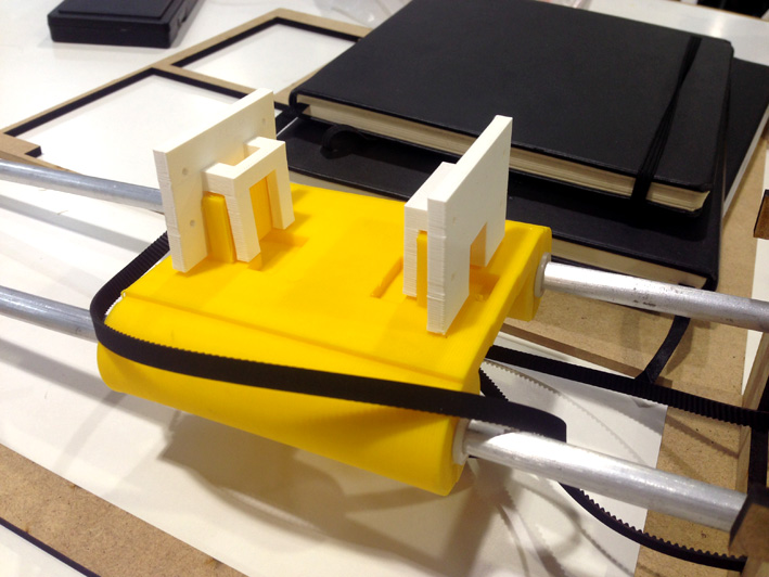
Apart of adding more components, I need to make the board slimmer, as on the
prototype will have a smaller space to be placed (just in the middle
of the yellow slider).
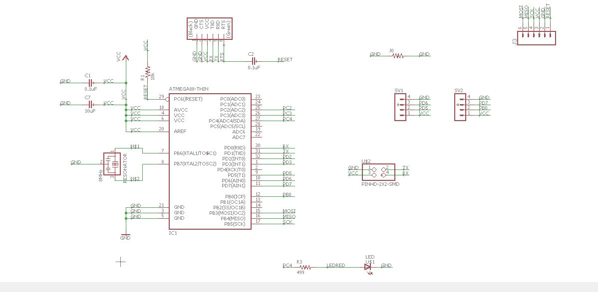
My Schematic Board
My Board with my new sonar connection + 2x2 SMD for the serial connection + thinner.
Final P.PNGs
Differences from the Input Board:
-Above, the serial connection is done with a 2x2 SMD pin, just in front of the vertical FTDI Header.
-At the right-hand side, the 1x06 has been turned 90 degrees to make the board slimmer.
-At the bottom, the second 1x04 connected to the second sonar.
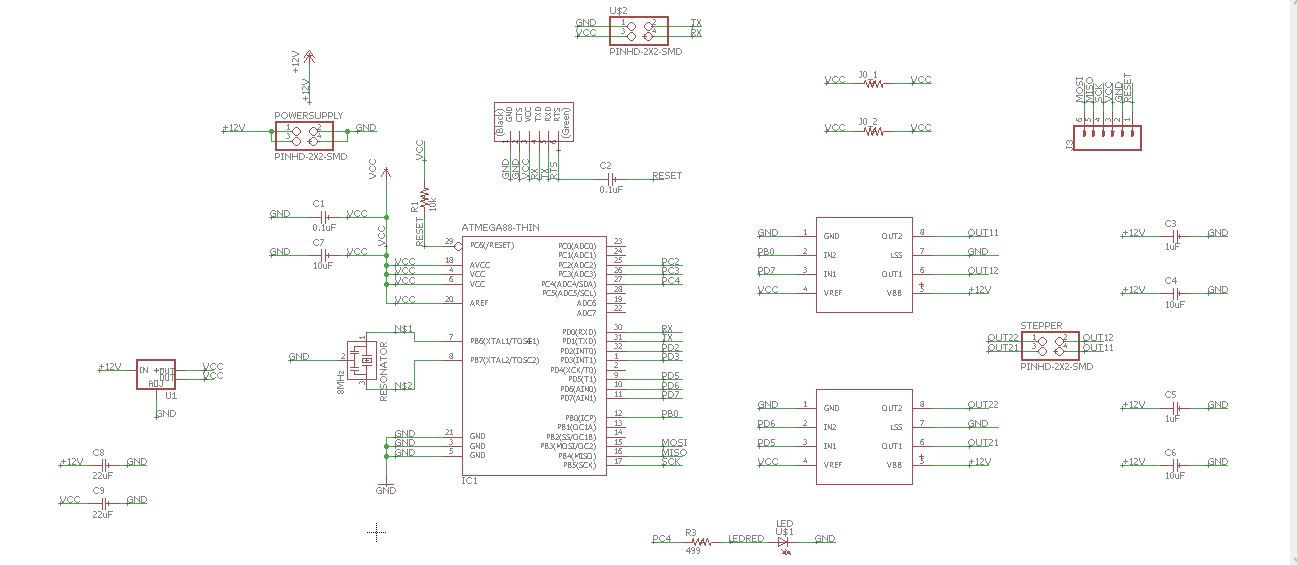
Output
For the outputs, as I am adding more components, the regulator is connected,
the 2x2 pin 12 volt supply is also connected and the 2x2 serial pin connection
as well.
My Schematic on Eagle Software:
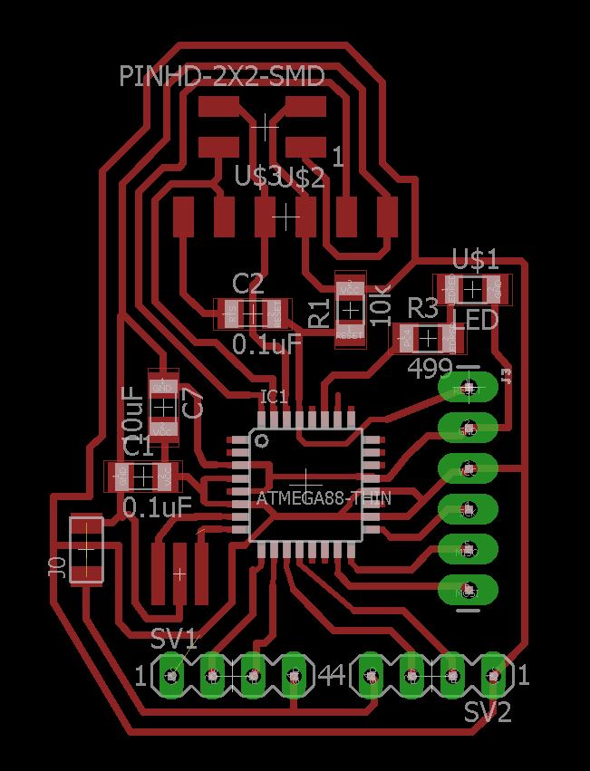
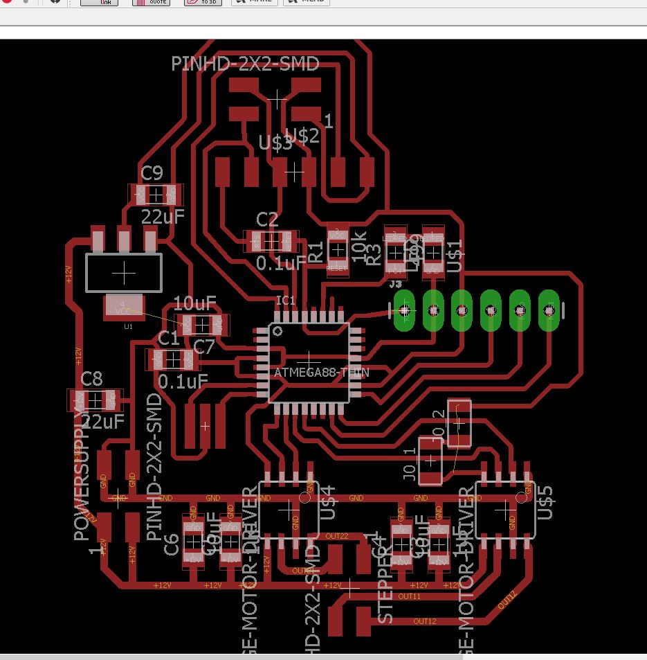
My Board:
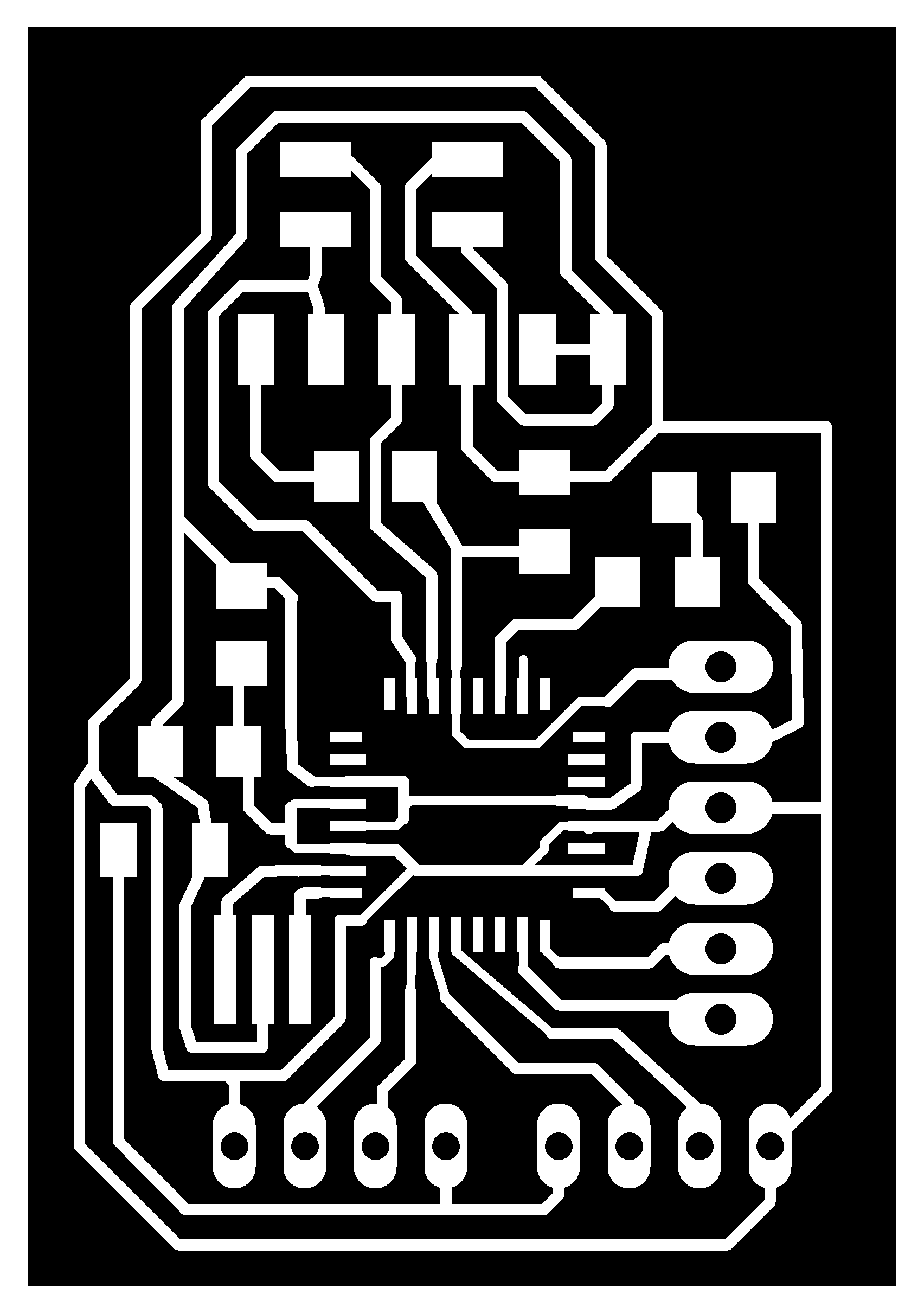
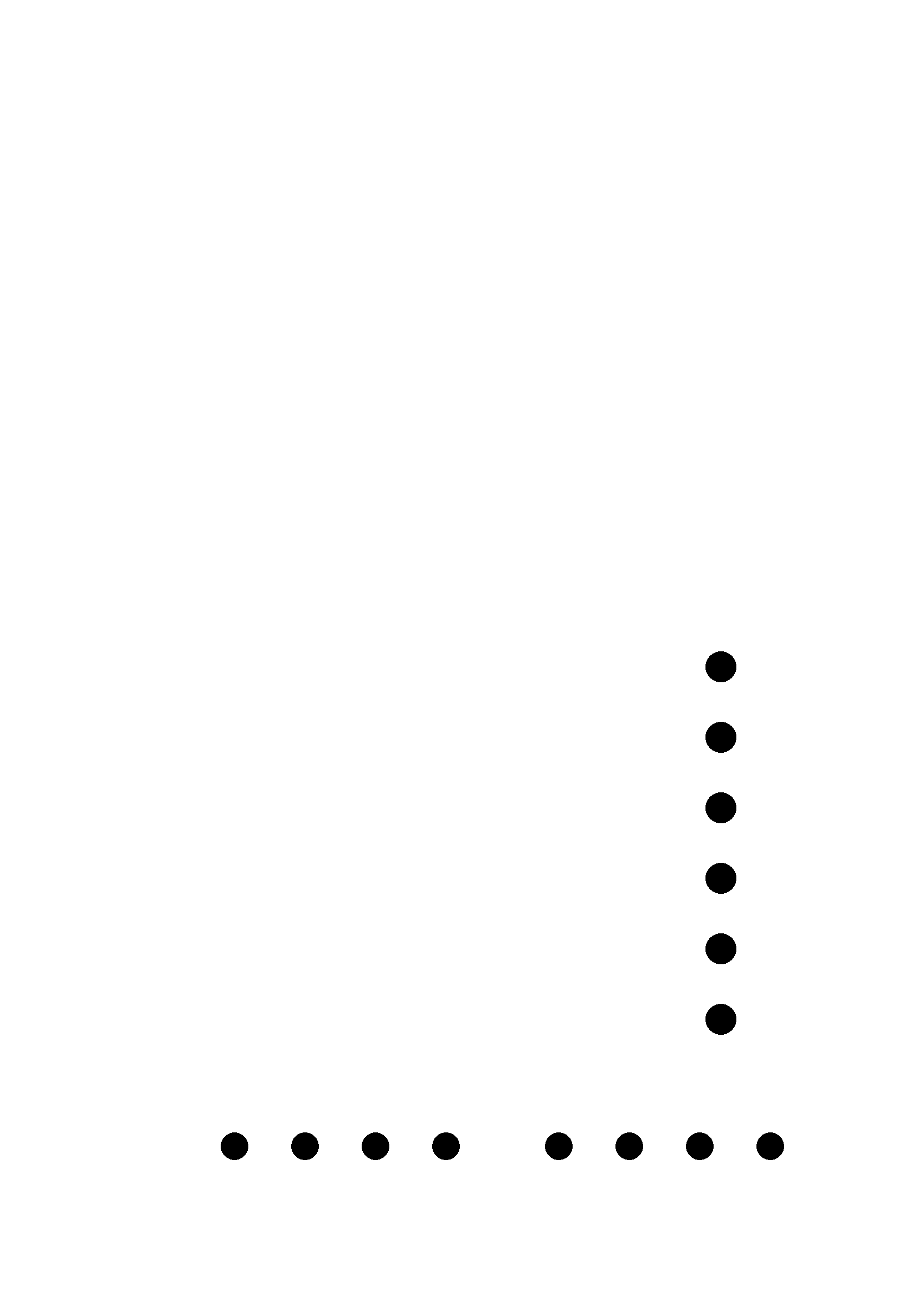
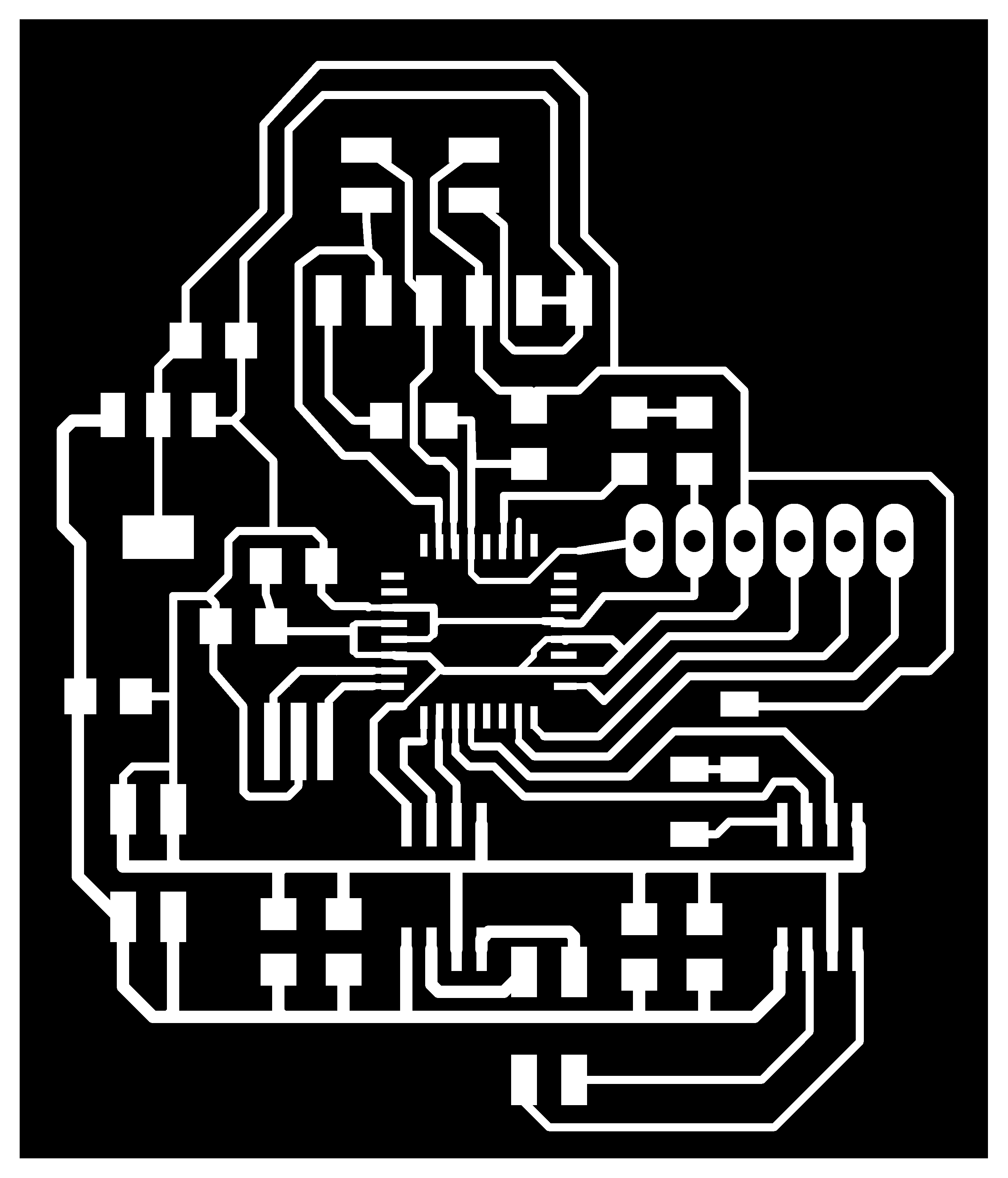
Final P.PNGs
Trace Width Website Calculator:
The lack of time made me go very quickly and forgot to take some pictures while
milling the boards. I followed the same process as in inputs, output,
electronic design and electronic production. Repeating the same process,
with several previous errors learnt such as with the Atmega 128 and 328
mcus and the modela.
Everything was perfect, with a little bit of rush as I had not much time, but very efficient.
Electronic Production
Electronic Design
Input Devices
Output Devices
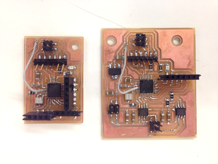
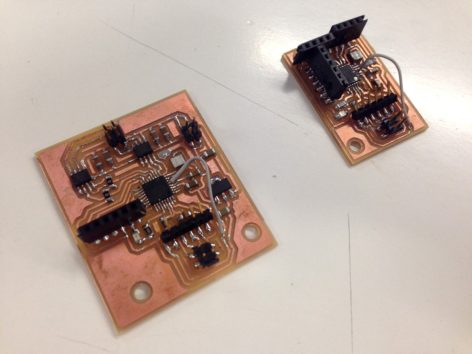
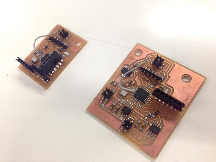
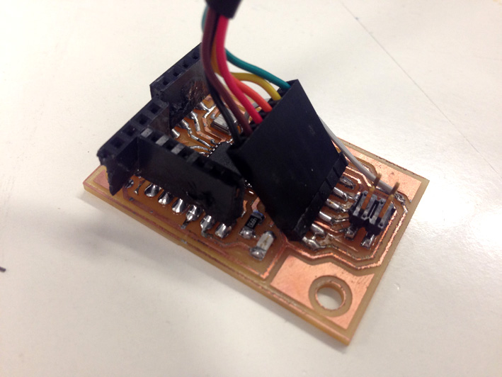
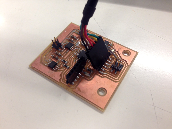
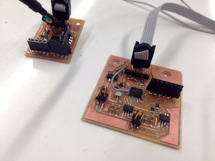
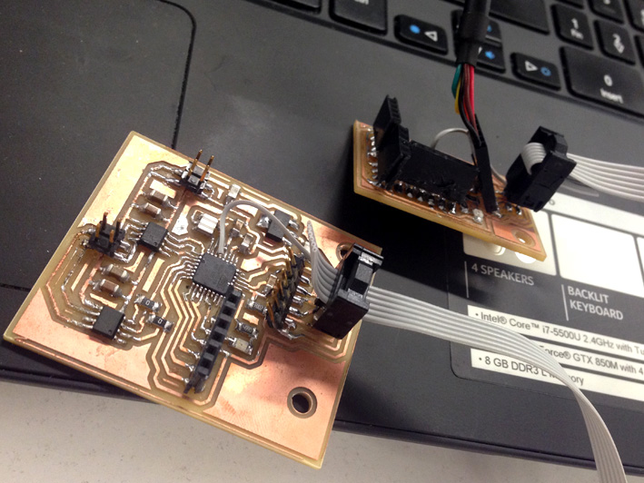
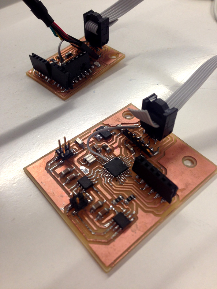
4. My Final Boards + All Components Soldered
While I was soldering, I had problems with certain mcu's pins, having to create
one bridge on each board to connect several traces. After making sure
everything has been correctly connected, I could take the next step to
create my serial communication.
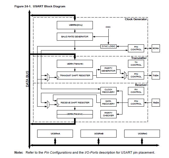
5. How Dows The USART work? (Universal Synchronous Asynchronous Receiver Transceiver)
This type of serial interface device can be programmed to communicate asynchronously
or synchronously with two or more boards together and communicate with
one another. There is a 'Master Board' which speaks to all the rest
(named 'Slave Boards'), calling the one the master orders.
IMPORTANT
It is important that all mcus have the same language, same baud rate and the same interpretation of ASCII data.
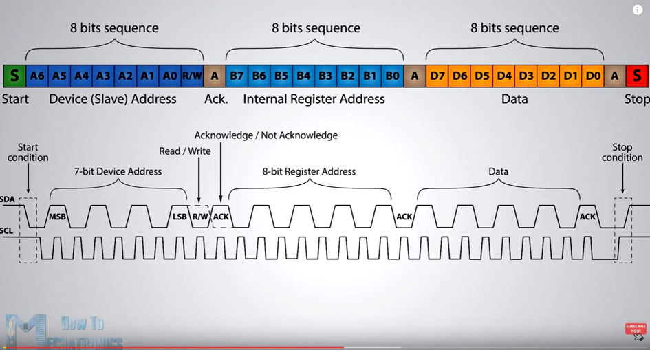
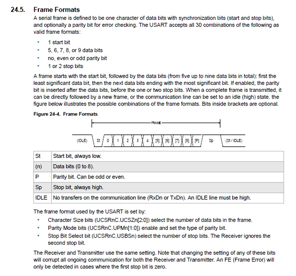
¿How does it start and finish?
The USART in synchronous mode transmits data in frames. Characters must be provided on time until a frame is complete.
Here is a diagram explaining the frame sequence:
Every frame that is used has a 'Start Bit' and a 'Stop Bit', which have been expresses and in green on the diagram.
In order for the USART to work correctly using serial communication, the pin that
transfer the information of the slave board need to be tri-stated, so
they can modify its mode (from input to output and vice versa), so when
a slave board is answering back, it is not interrupted by other signals
made by other slave boards.
Here is the ATmel 128 Block Diagram:
6. Programming: Strategy
The program I wanted to make is based on Neil's and code to create a new behaviour when the slave boards answer.
My idea is to connect two slaves boards to my computer and call them. Each one of them should receive the information, and the one selected must execute the next program:
-Turn on the red led 3 times.
-The one that does not activate must turn the led on once, quicker.
Tri-state Logic Defintion:
The tri-state mode allows an output pin to remove effectively the output signal from the circuit, avoiding bus contention.
(bus contention: a state of the bus in which more than one device on the bus attempts to place values at the same time.)
The main use for this is to have several outputs connected to a serial communication bus sharing the same output lines. As a reminder, the bus communication only can listen at one device at a time, at a certain baud rate).
Tri-stating The Pins On My Board
The way I have tri-stated the pins is as follows:
-I declare pin 1 as variable Tx.
-I digitalWrite the Tx pin as LOW, with no voltage in it continued by specifying to be an output.
-Change its mode as an Input (Remember my Tx pin is connected to the Rx of the computer). It is important to be a Input to make sure no signal travels through this path and messes up other Tx signals from other boards.
-Then, if the character read through serial communication corresponds with the id of the board, change number 1 pin to output and transmit a message followed by turning on 3 times the red led.
On the other hand, I turn on the red led by digitalWrite HIGH the red led pin.
It is important to say that the input board (the board to which I connect 2 sonars), has an id = 1 while the output board has an id = 2.
Once I successfully connect these two boards, I will be able to connect my project together and start programming for it.
Commands I have used on this code
declaring integers and characters: 'INT', 'CHAR'
Serial.begin (9600): having a baud rate of 9600 on each board.
digitalWrite: for both Tx pin and the red led
pinMode: to make the red led pin an output and change back and forth the Tx pin from Input to Output.
conditional function: if(); if there is serial communication, enter the if, if not, do nothing.
else: if it does not enter, flash the led quickly making sure it has received the character.
Serial.available(): check if there is any character on the serial communication.
Assign the variable 'encendido' to what it has been read from the serial communication.
Serial.println (): print back on the serial monitor which motor is active.
Videos Of How The Boards Behave Separately
We can see how both boards have been programmed by taking a look to their behaviour.
Input Board - Id board: 1
First I enter number 1 on the screen monitor, followed by turning on the red
led 3 times. Secondly, I enter the number 2, followed by a quick flash, meaning
that the board has received the data but it does not correspond to
its id.
Output board - Id board: 2
First I enter number 1 on the screen monitor, followed by a quick flash, meaning
that the board has received the data but it does not correspond to its
id. Secondly, I enter the number 2, followed by turning on the red
led 3 times.
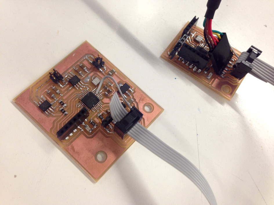
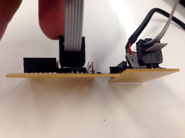
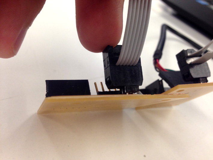
Both Boards Connected Together
Once I have all boards connected together with the computer, I start testing them.
Videos - Networking
The video showing my strategy: calling board number 1 first, then call board number 2 second.
On this second video, I call number 1 first, then number 2, then number 3 and number 4. Back to number 1 and repeat.
7. Programming: Code
Slave 1: Input Board
//slave 1 - ref in; IF OF THIS BOARD: 1
int encendido = 0;

int id = '1'; // id 1
int Tx = 1; // pin Tx

const int led = A4; // declaring blue led on a4 pin


//setup
void setup() {

Serial.begin(9600);  //baud rate 9600

  pinMode(led, OUTPUT); //activation led

}


//loop
void loop() {

// Tx in tristate: it becomes an input
digitalWrite(Tx, LOW);
pinMode(Tx, OUTPUT);
pinMode(Tx, INPUT);

digitalWrite(led, LOW);
//reading serial communication

char data;

     if(Serial.available()){
          encendido= Serial.read();
             if(encendido == id){
               pinMode(Tx, OUTPUT);
              Serial.println("Node 1: ACTIVE - Node 2: not active");
              digitalWrite(led, HIGH);
              delay (500);
              digitalWrite(led, LOW);
              delay (500);
              digitalWrite(led, HIGH);
              delay(500);
              digitalWrite(led, LOW);
                delay(500);
              digitalWrite(led, HIGH);
              delay(500);
              digitalWrite(led, LOW);
                delay(500);
              }
             else  {
              digitalWrite(led, HIGH);
              delay (50);

              }
       }
  }
Slave 2: Output Board
//slave 2 - ref out; ID OF THIS BOARD: 2
int encendido = 0;

int id = '2'; // id 2
int Tx = 1; // pin Tx

const int led = A4; // declaring blue led on a4 pin

//setup
void setup() {

Serial.begin(9600);  //baud rate 9600

 pinMode(led, OUTPUT);   //activation led's pins


}


//loop
void loop() {

// Tx in tristate: it becomes an input
digitalWrite(Tx, LOW);
pinMode(Tx, OUTPUT);
pinMode(Tx, INPUT);

//all leds off
digitalWrite (led, LOW);

//reading serial communication

char data;

     if(Serial.available()){
          encendido= Serial.read();
             if(encendido == id){
               pinMode(Tx, OUTPUT);
              Serial.println ("Node 1: not active - Node 2: ACTIVE");
              digitalWrite(led, HIGH);
              delay (500);
              digitalWrite(led, LOW);
              delay (500);
              digitalWrite(led, HIGH);
              delay(500);
              digitalWrite(led, LOW);
                delay(500);
              digitalWrite(led, HIGH);
              delay(500);
              digitalWrite(led, LOW);
                delay(500);
              }
             else  {
              digitalWrite(led, HIGH);
              delay (50);

              }
       }
  }
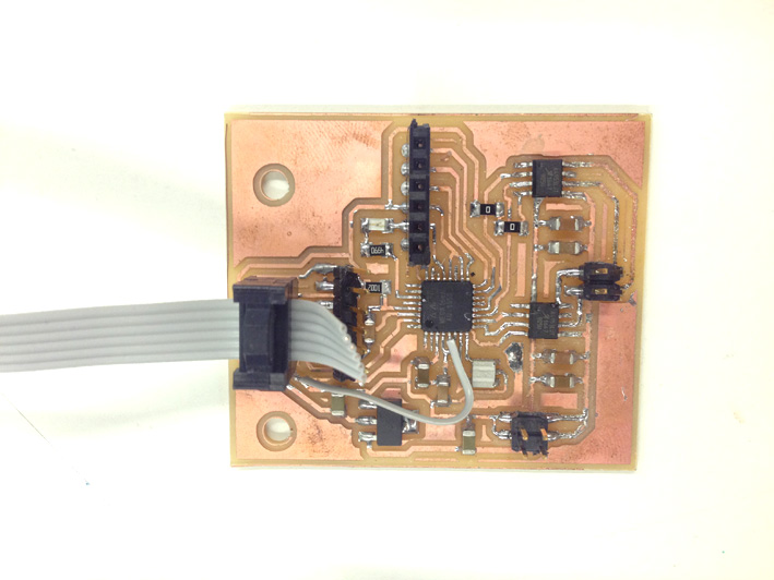
8. Problems Accounted
Electronic Bridge
While I was soldering the board, I accidentally broke some copper where
the mcu pins are placed. I had to create on each board a bridge with an
additional wire.
The result:
Printing On My Serial Monitor
Although the serial communication was successfully done, knowing that both boards
received the data sent and activating the one that has been ordered from the
computer, I had a minor problem. The data sent back does not appear on the serial
monitor. It is a minor problem with ASCII data.
IMPORTANT: During the Project Development page, this has been resolved with no more issues accounted.