Procedure:
0. Assignment
1. Safety Data Sheet (MSDS) + Technical Data Sheet (TDS)
2. Materials I Need
3. Coupon - Design It
4. Coupon - Creating It
5. Coupon - Building It
6. Coupon - Conclusions
7. My Composite - Designing the Mould
8. My Composite - Creating the Mould (CNC Machining)
9. My Composite - Physical Mould
10. My Composite - Building It
11. Problems Accounted
12. Download Files
0. Assignment
Read the material safety data sheet (MSDS) and technical data sheet (TDS) for the resins that you are using
Design and fabricate a 3d mould and produce a fibre composite part in it.
LEARNING OUTCOMES
Demonstrate workflows used in mould design and construction.
Select and apply suitable materials and processes to create a composite part.
HAVE YOU...
...shown how you have made your mould and created the composite.
...described problems and how you fixed them.
...included your design files and 'hero shot' photos of the mould and the final part.
...Read and linked to the material safety data sheet (MSDS) and technical data sheet (TDS) for the resins that you are using.
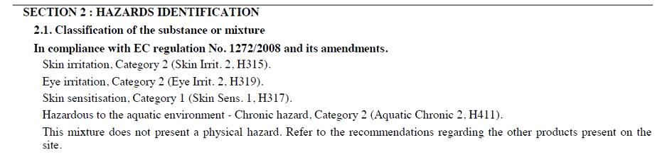
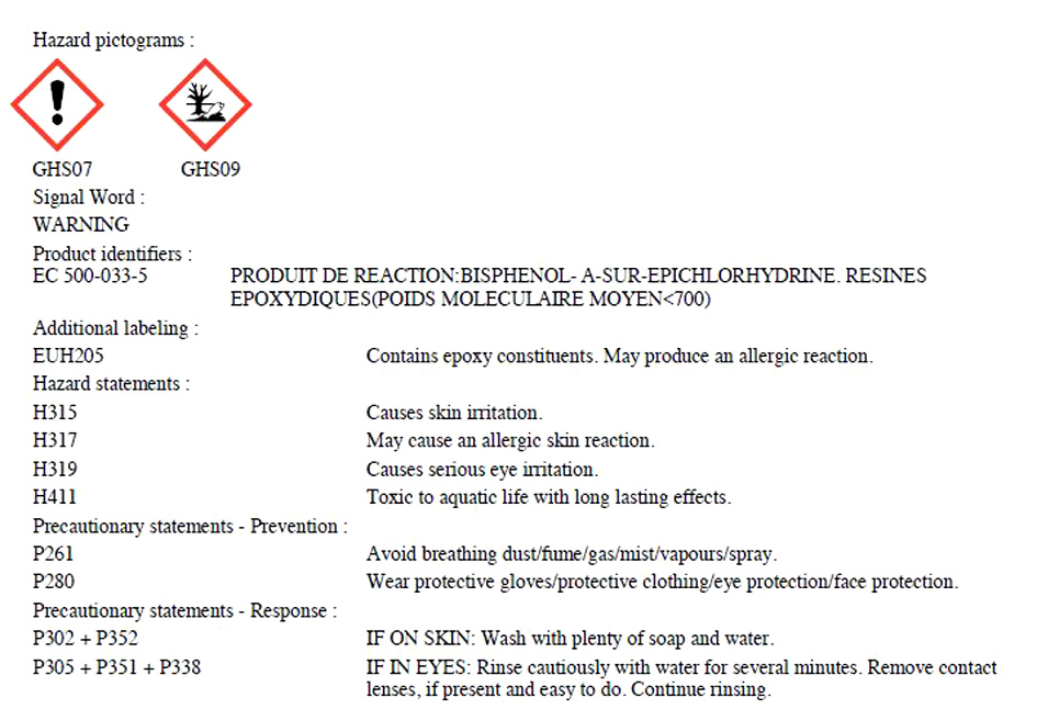
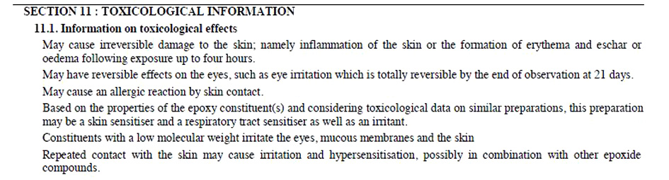
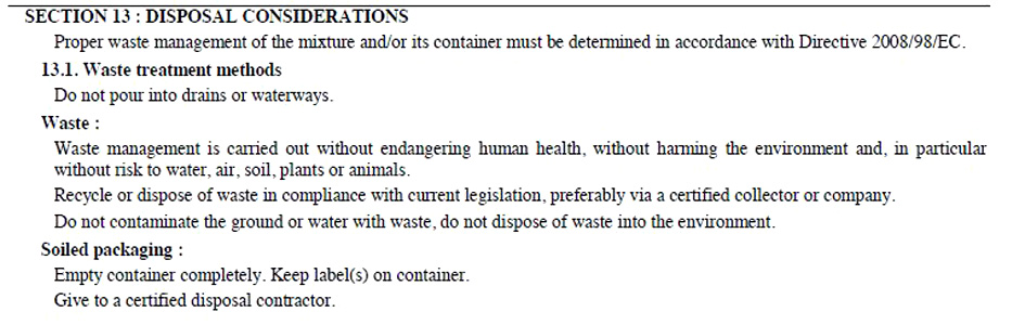
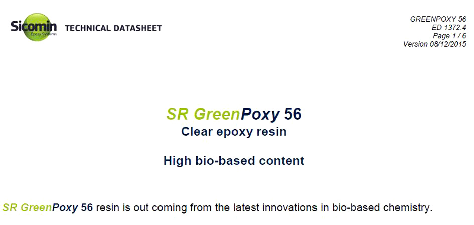
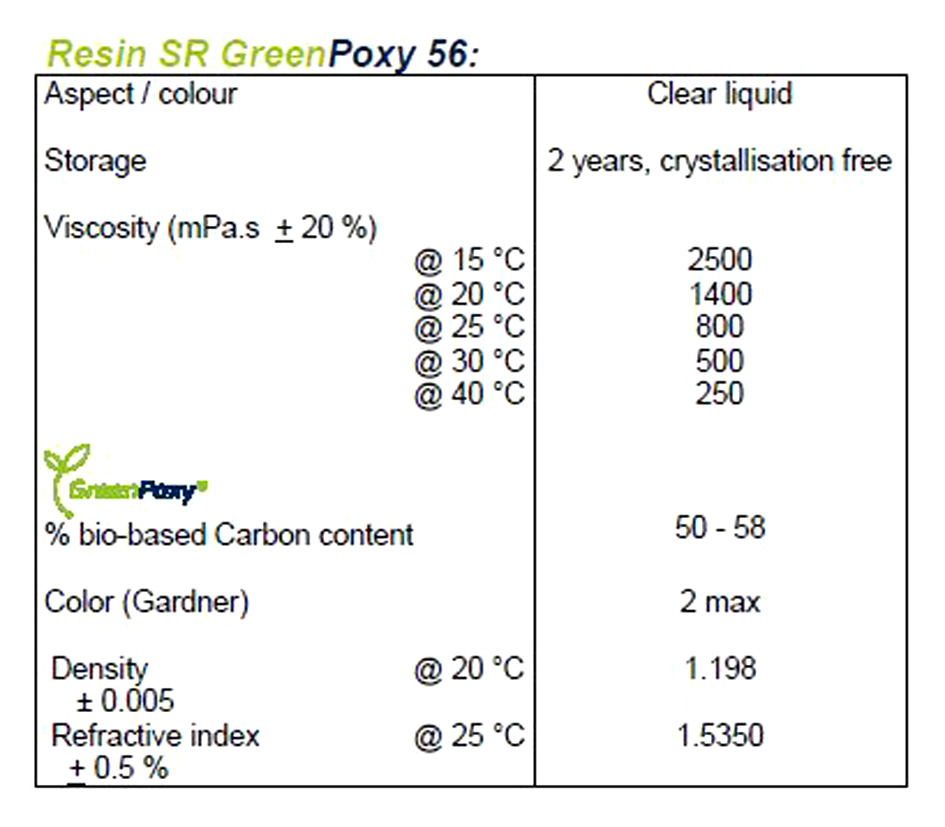
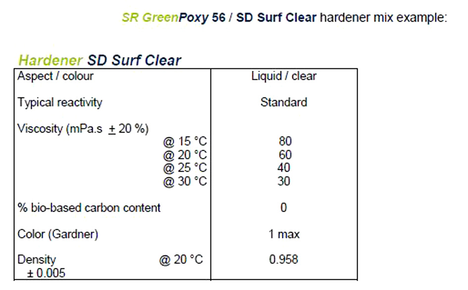
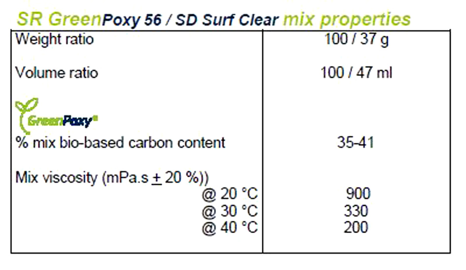
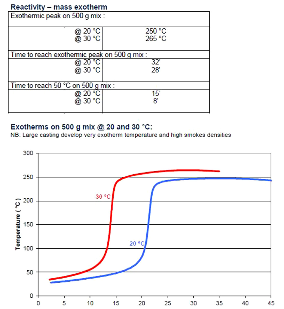
1. Safety Data Sheet (MSDS) + Technical Data Sheet (TDS)
With a 500 grams of mix at 20°C and 30°C atmospheric temperature:
-the exothermic peak reaches 250°C / 265°C.
-time to reach exothermic peak: 32 minutes/ 28 minutes at 30°C.
-time to reach 50°C, 15 minutes/8 minutes.
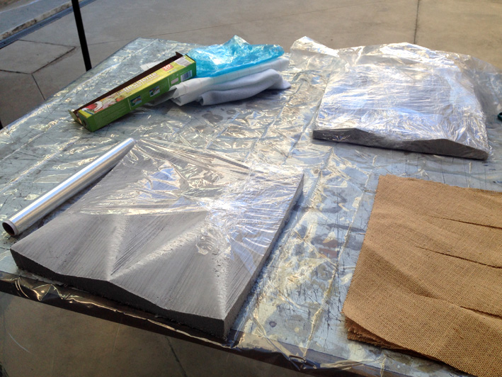
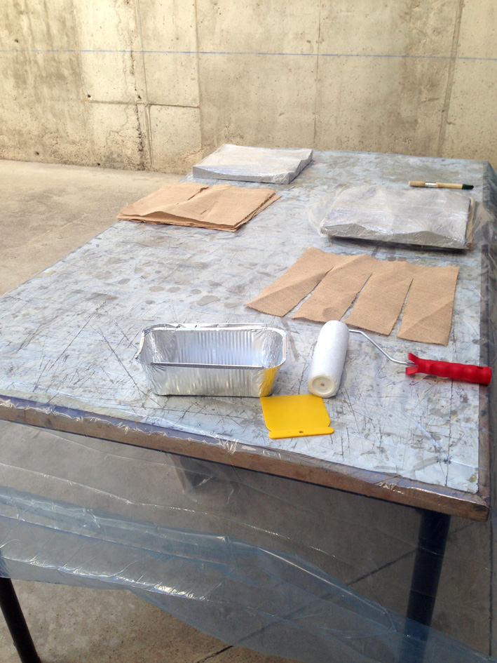
2. Materials I Need
-Medium Density Wood 3mm/4mm
-Natural Fibre
-Scale
-GreenPoxy 56 Resin
-Acetone
-2 small Plastic Cup (each time using resin)
-1 Big Plastic Cup (each time using resin)
-2 Pairs of Gloves
-1 Brush
-1 Roller
-Plastic Film
-Tape
-1 Aluminium Tray
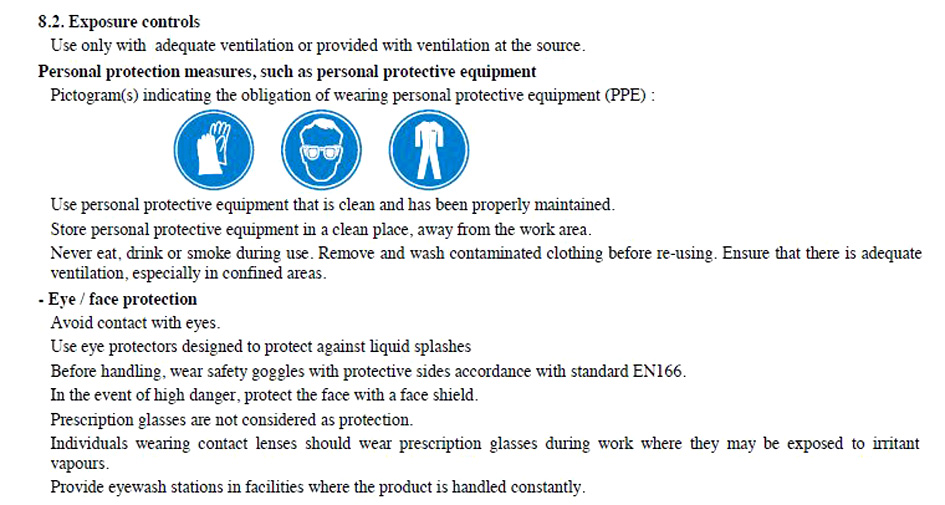
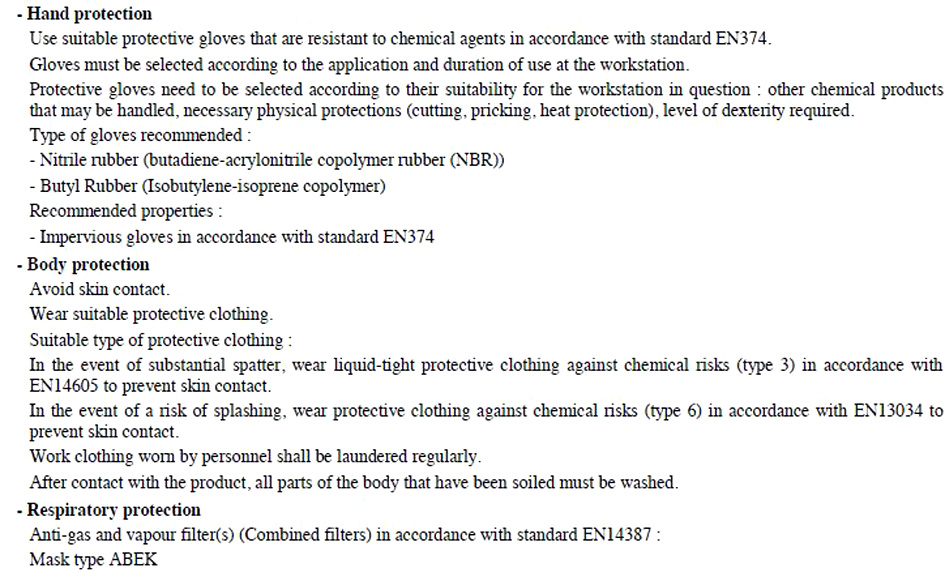
-Protective Glasses
-Face Protection
-Body Protection
-Breathing Protection
-Vaseline
-Weight
-Exterior Well Ventilated Area
-CNC Machien
-Lasercutter Machine
-Water
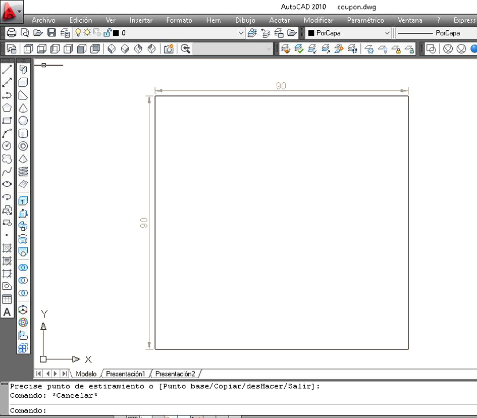
3. Coupon - Design It
Before starting with the design, first I want to go through the whole process of designing, creating and building
my own composite with a small coupon 9x9cm.
I want to experiment with a 10 layer composite made out of natural fibre and GreenPoxy 56. By the time I started to
make my own composite, my colleagues did already two of them. To change the way we made them, as Dani and
Álvaro had problems with the ratio resin : natural fibre, I discussed with my instructor to raise the quantity
of resin used.
Dani and Álvaro used a 50:50 ratio (resin : natural fibre) having some problems with not having enough.
This time, I will be using 100 : 50 ratio and see what happens.
My colleague's website where their coupon's experiment is explained:
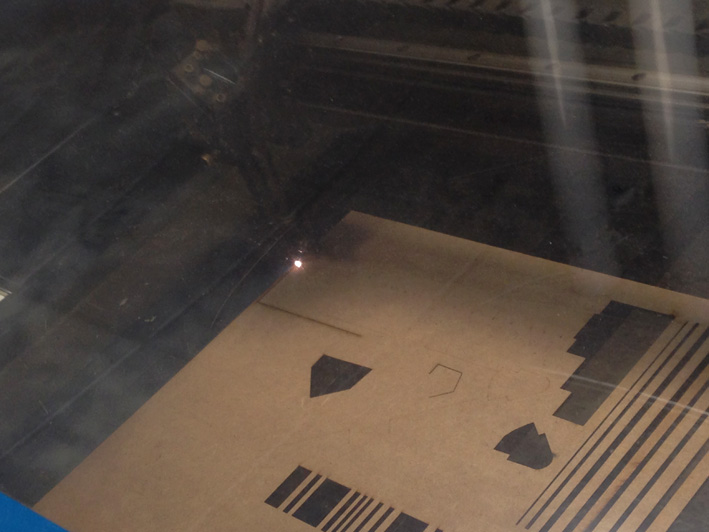
Preparing the dxf file and getting ready to cut it.
Let's go to the Lasercutter machine.
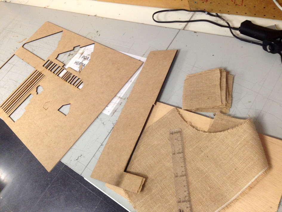
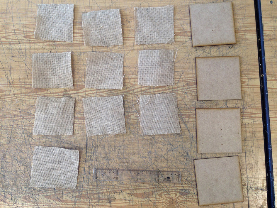
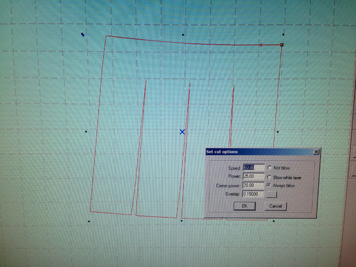
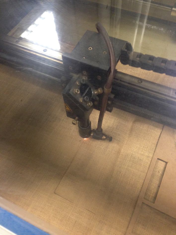
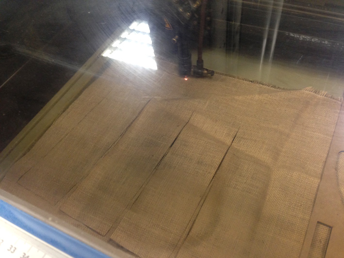
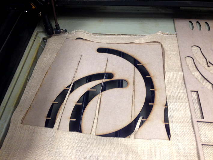
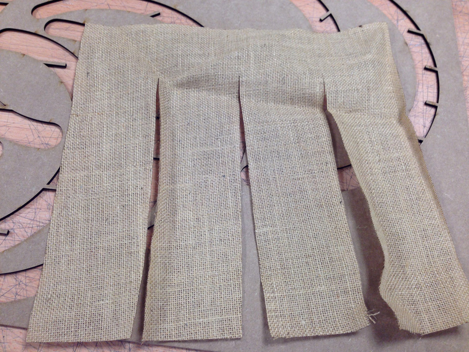
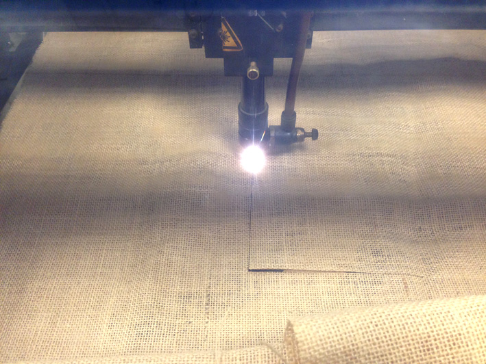
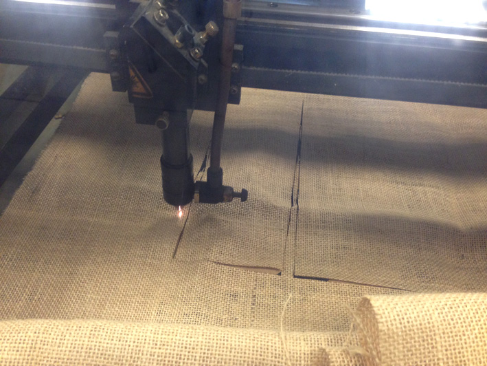
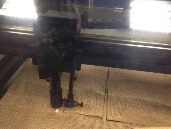
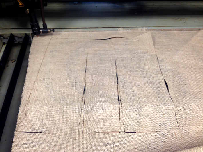
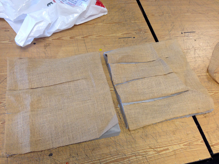
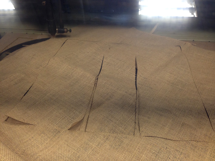
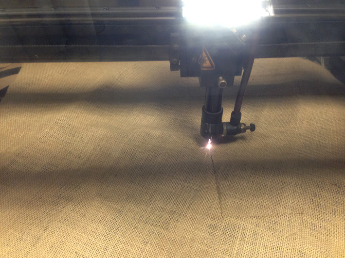
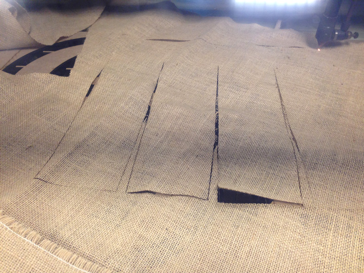
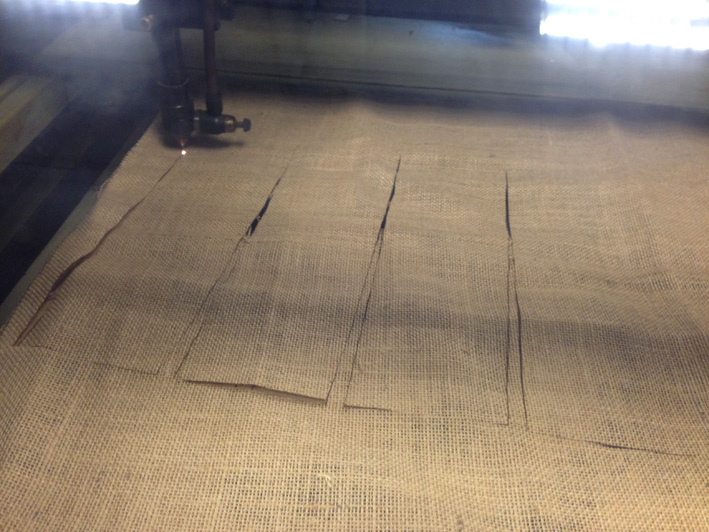
4. Coupon - Creating It
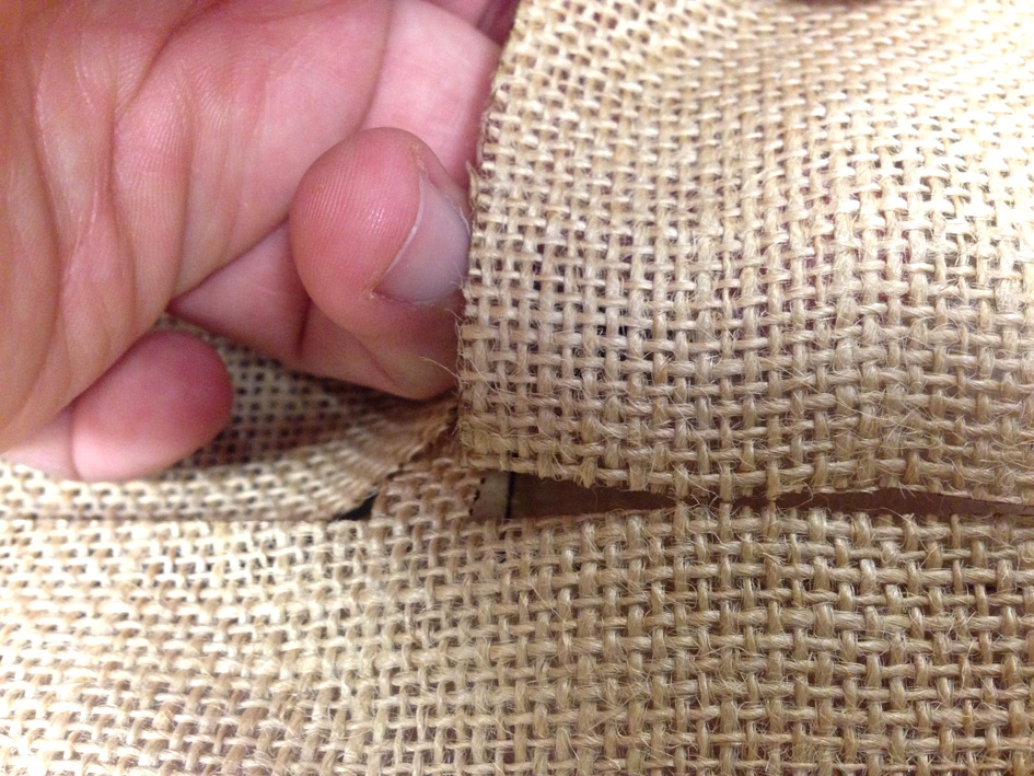
As they are very small pieces, it was very quick to cut:
Preparing the material: medium density wood for formwork + natural fiber cut
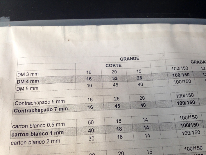
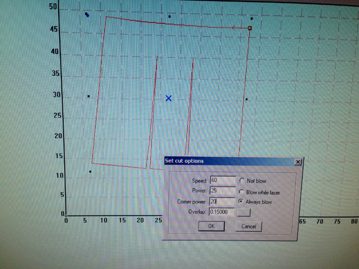
Parameters used for the natural fiber:
Speed: 60
Power: 25
Corner Power: 20
Parameters used for the medium density wood 3mm:
Speed: 16
Power: 20
Corner Power: 15
Result
Everything is ready to start using the GreenPoxy 56 resin.
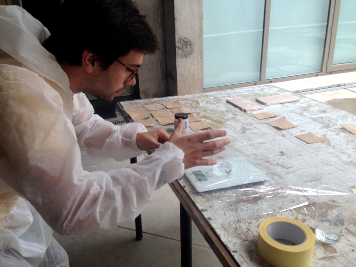
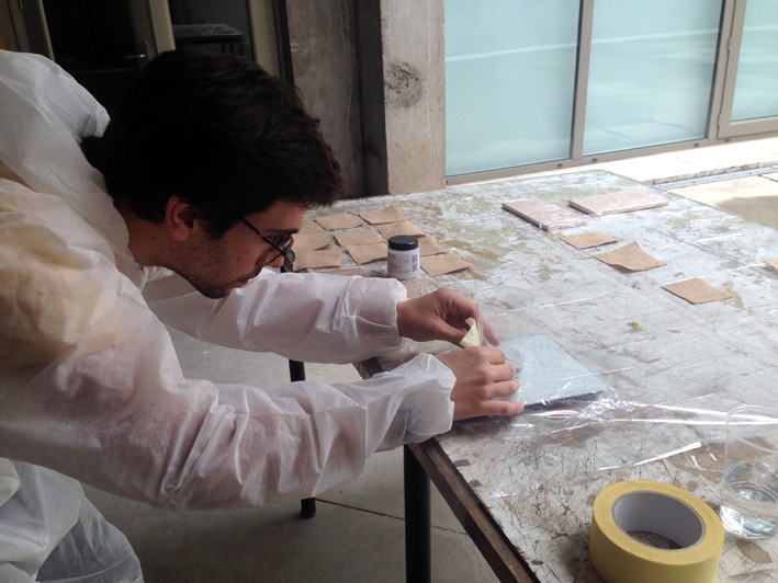
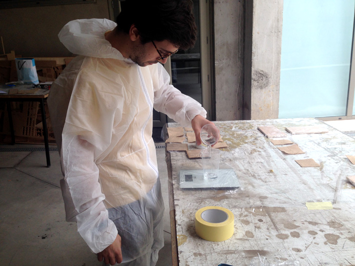
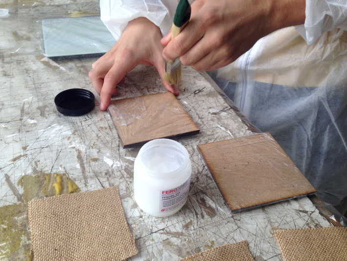
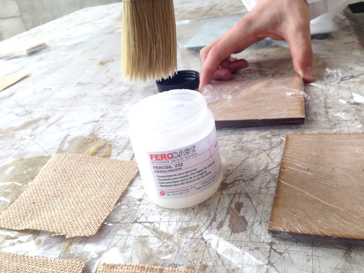
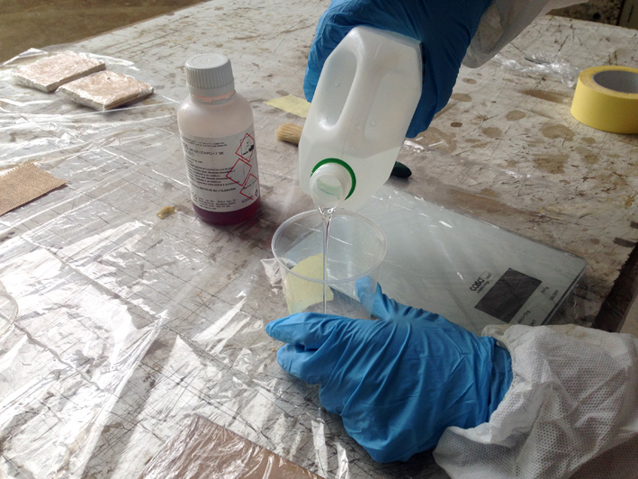
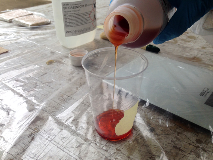
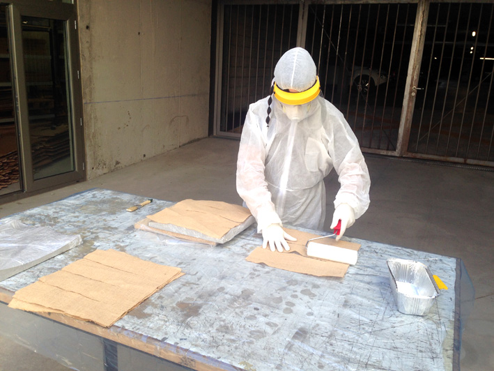
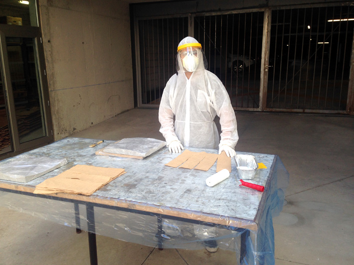
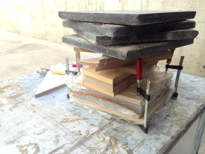
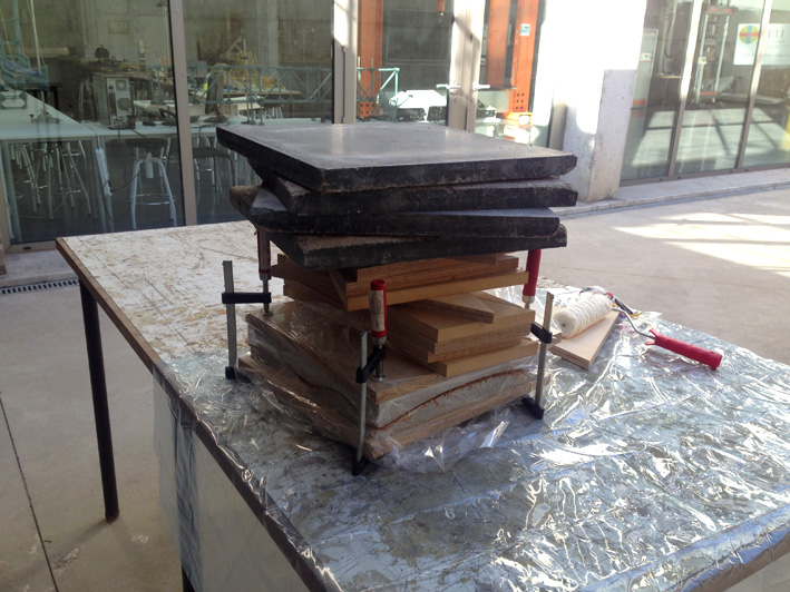
5. Coupon - Building It
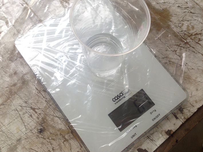
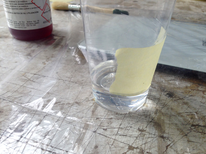
Getting Everything Ready - Calculating Quantity of Resin Needed by Volume
Total Volume:
Coupon: 9x9x0.8cm= 64.80 cm3 (0.8cm corresponds to the coupon's height; each layer is 0.8 mm: 10 layers x 0.8mm = 8 mm).
As mentioned before, instead of using the 50:50 ratio for that amount of volume, I dicussed with Dani, Álvaro and my
instructor to try and double the amount of resin corresponding to that proportion. In the end, we will have
twice as much volume of resin related to the fibre used.
Having a total volume of 64.80 cm3, 32.40cm3 corresponds to fiber. Applying what has been said the paragraph above,
I will need 64.80 cm3.
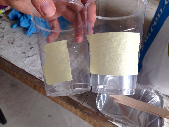
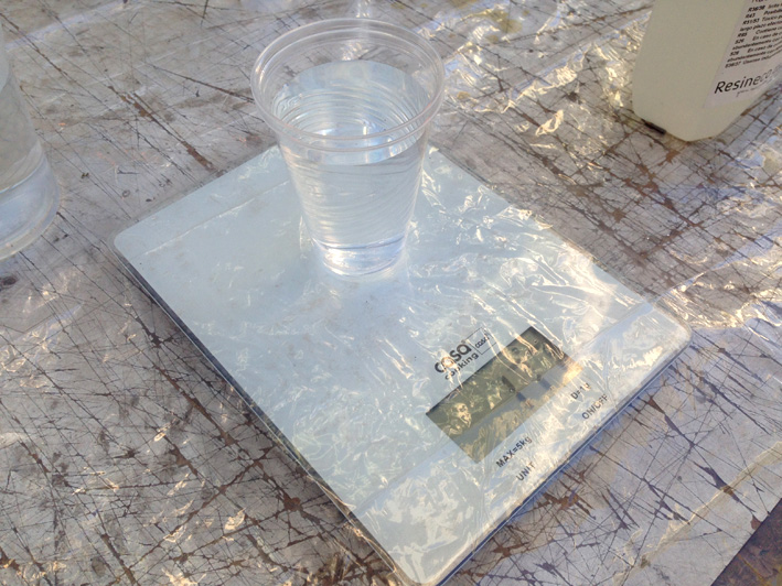
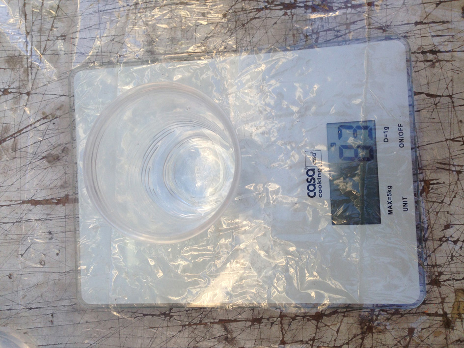
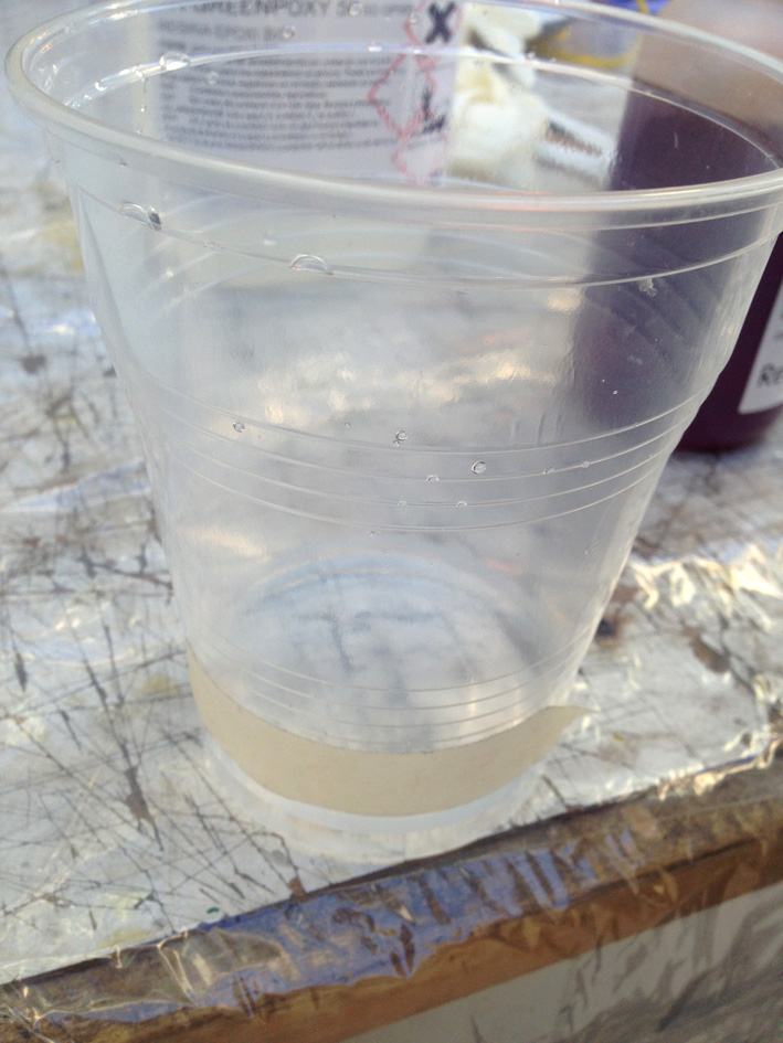
With water, we calculating the volume needed inside the cup and marked it with tape.
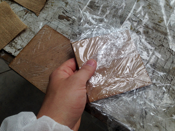
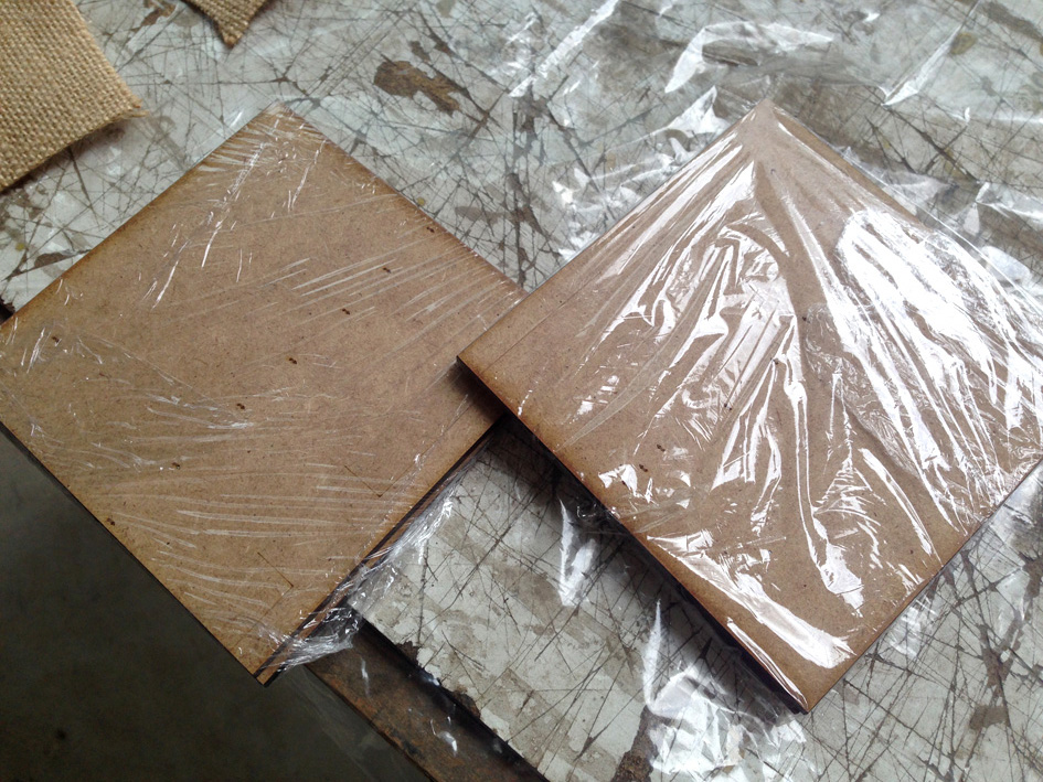
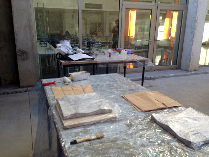
Starting to protect the MD formwork with plastic film + vaseline:
Gloves ON
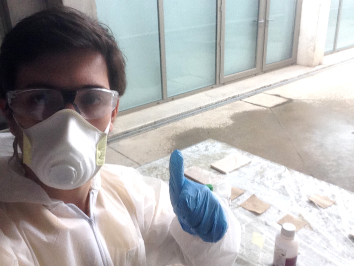
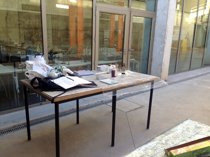
Getting Ready To Use Resin: Protection ON
Starting With The Mixture
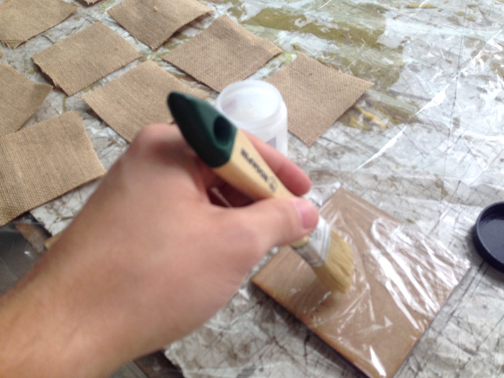
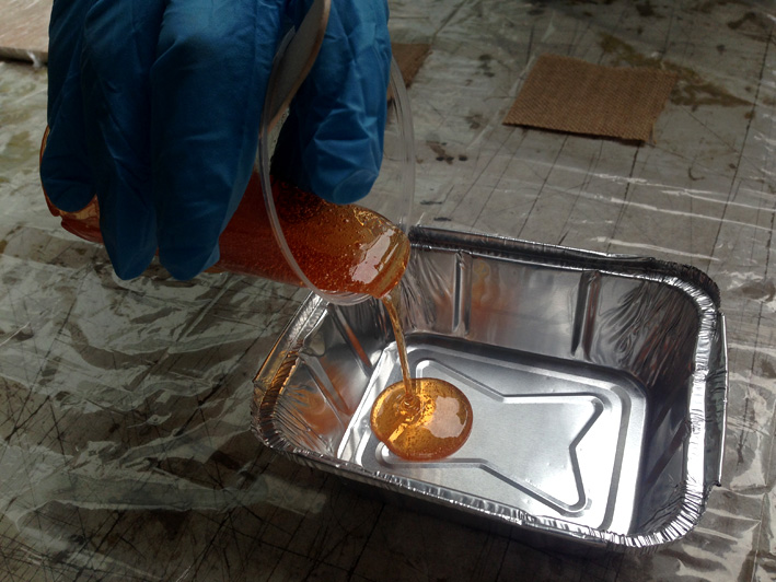
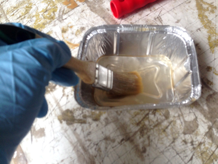
Once mixed, pour into the aluminium tray and start creating my composite:
As we were two and the chemical reaction gave us just a few minutes to do everything, no pictures were taken
during the process.
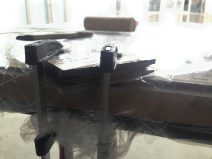
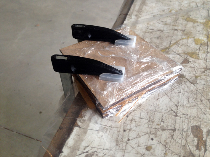
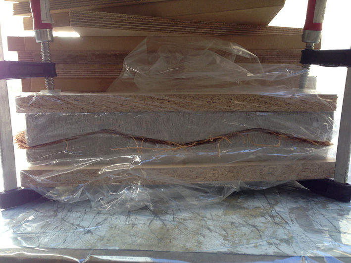
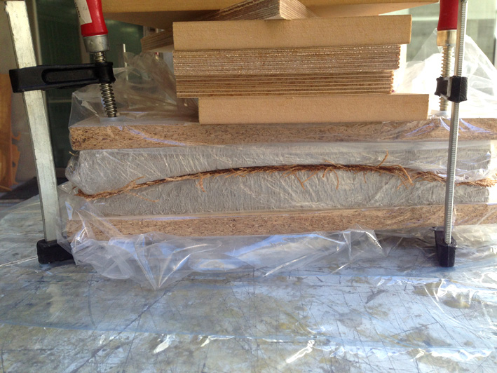
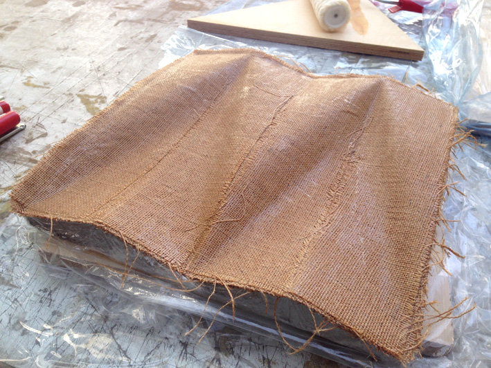
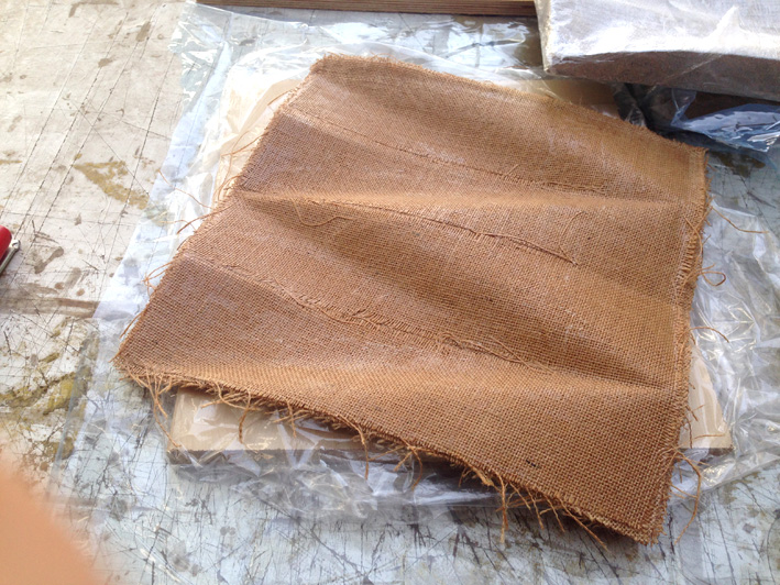
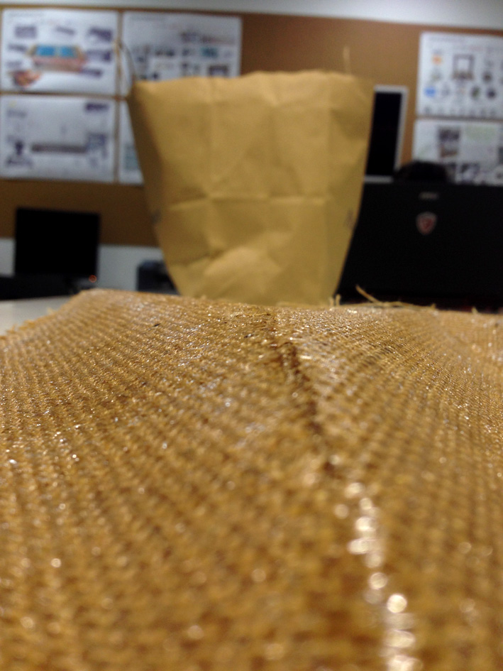
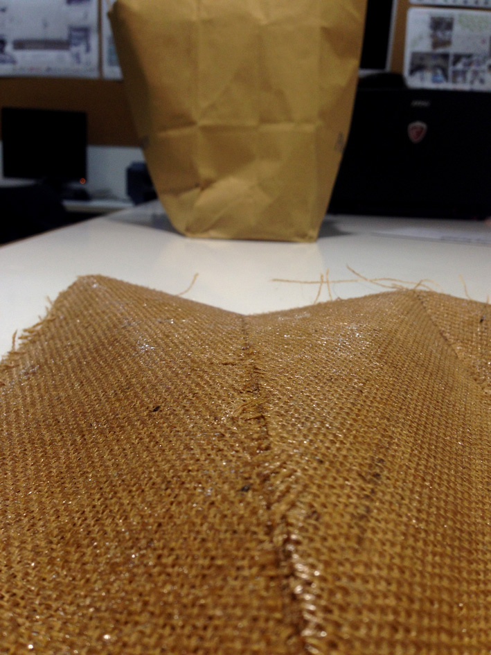
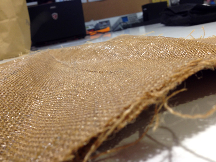
Once finished and having everything compressed, let it cure:
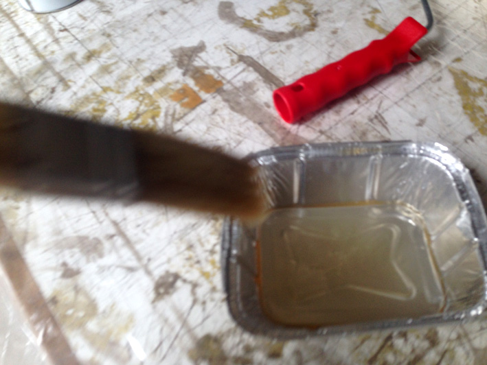
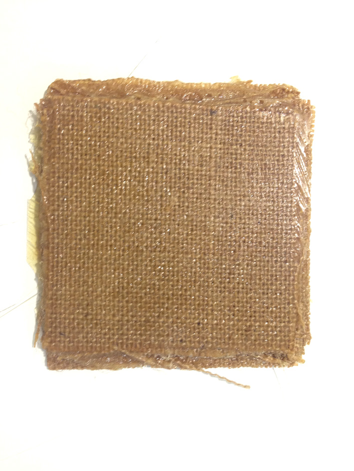
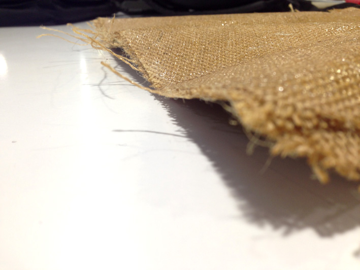
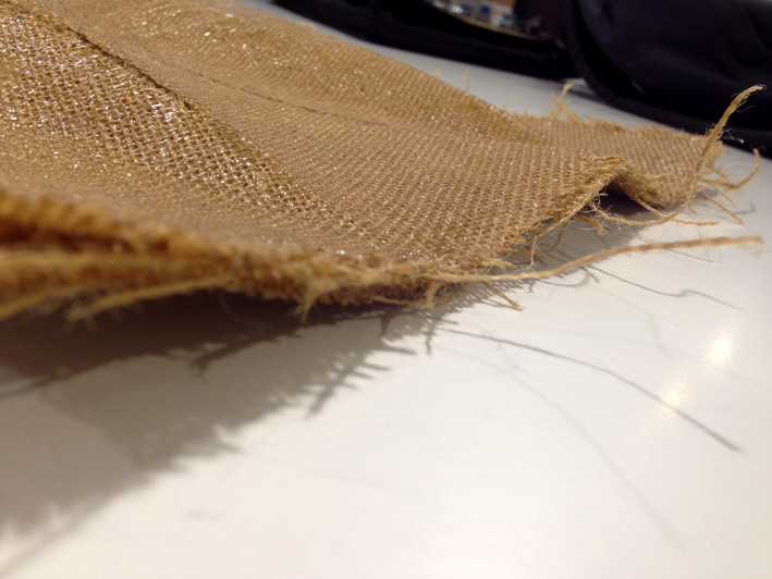
Acetone Cleaning
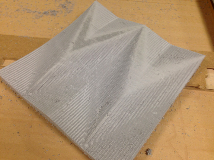
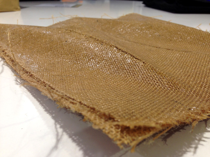
Final Result
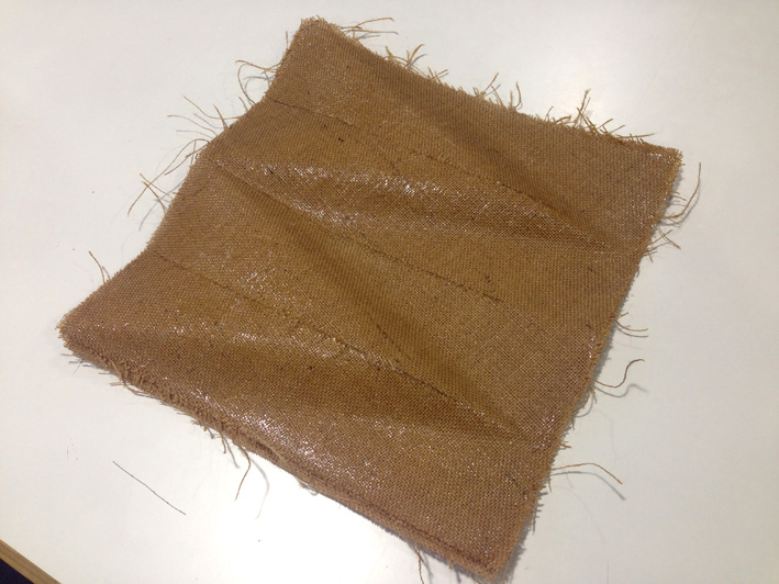
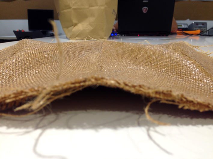
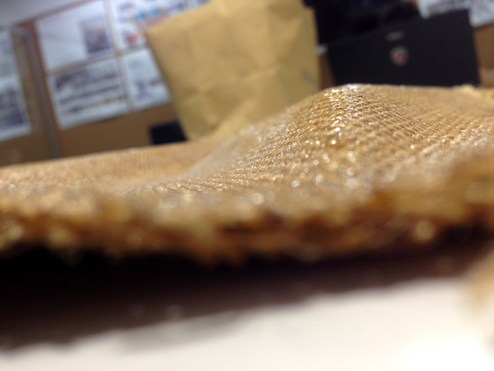
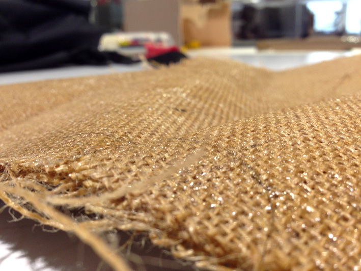
6. Coupon - Conclusions
Too much resin. It may not appear on the picture, but in reality, there is resin at the edges of the coupon without having
any natural fibre in it. It is much harder than my colleague's coupon, but there are more ways of using less
resin to have the same result.
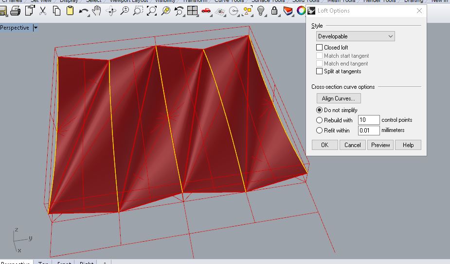
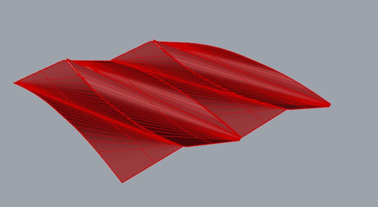
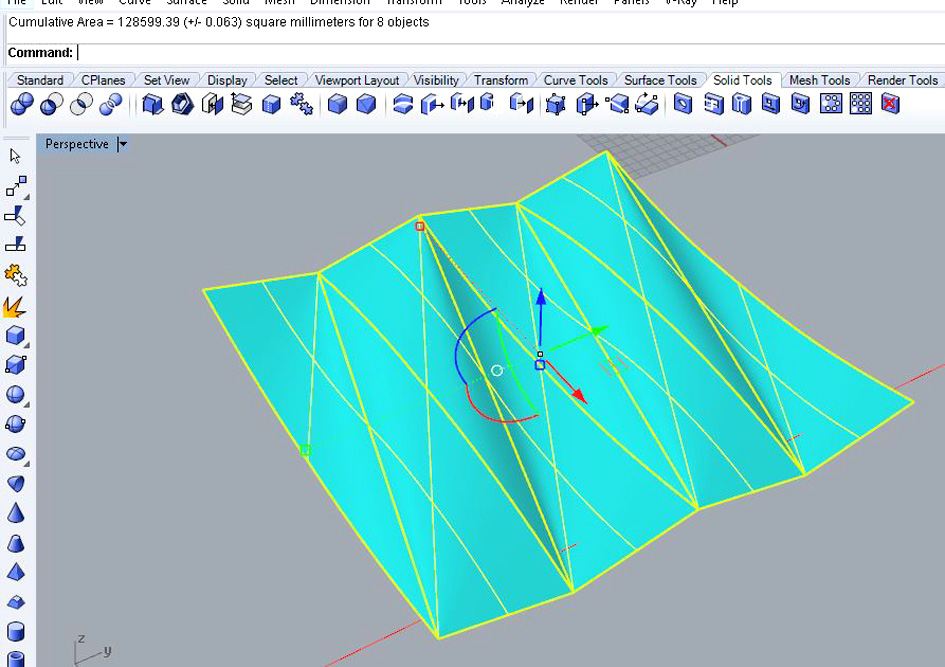
7. MY COMPOSITE - DESIGNING THE MOULD
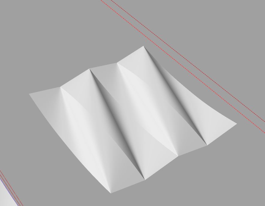
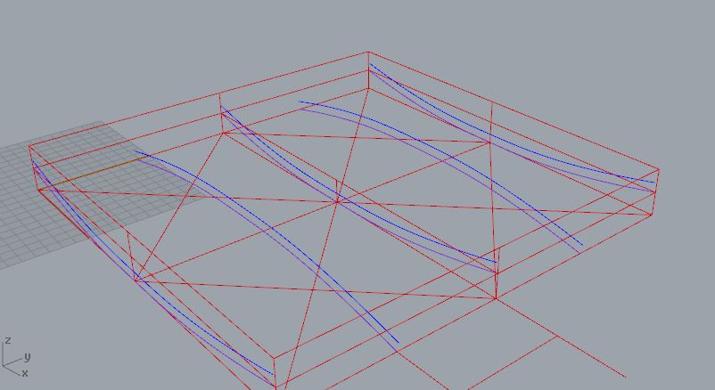
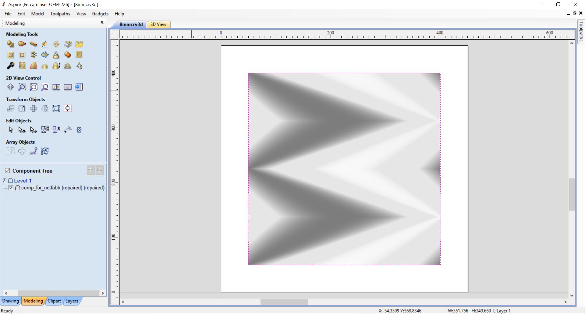
For this assignment, what I wanted to fabricate is a surface made out of epoxy resin and natural
linen fibre. This surface had to have different slopes symmetrically back and forth to analyze
how a composite is done with it.
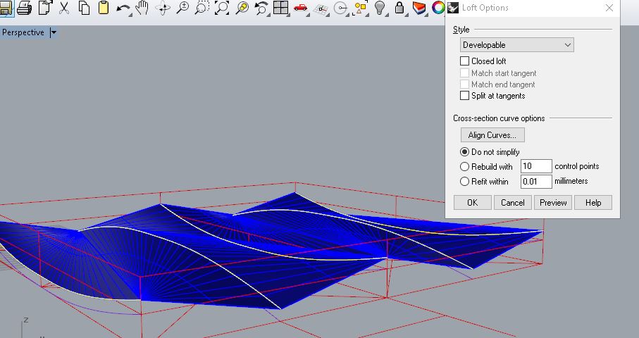
To design it, what I did was to create the main curves of the design and then used the command 'loft'
to create the surface.
I wanted it to be a two-sided closed mould. Therefore, I needed to create
two different parts, the offset one from the other the width I considered. The thickness of the
composite I estimate it to be 8mm. The thickness of my natural fibre is about 0.8mm each layer,
and having 10 layers, that will be about 8mm.
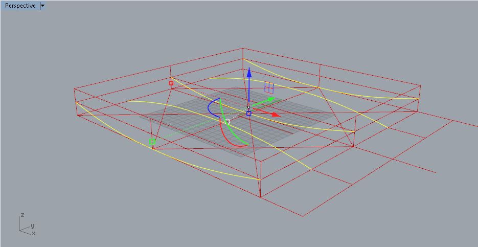
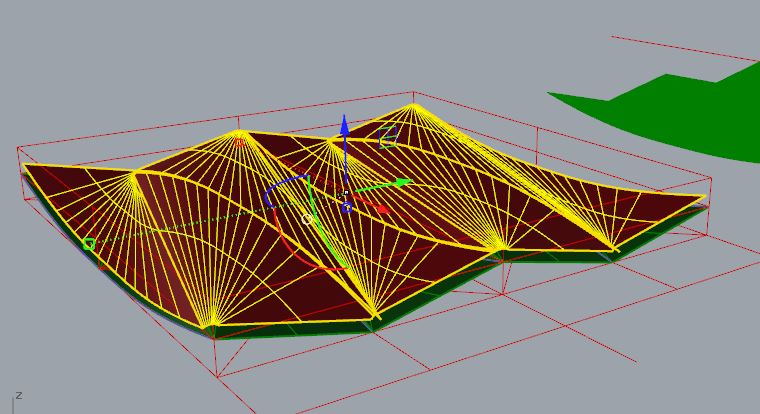
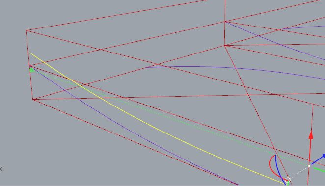
Creating the Second Layer
What I did then was to select the surface I just did and make an offset of 8mm .
It did not work. The offset surface broke, not putting together the different parts that the surface was made out of.
What I realised is that to have a nice clean surface, I needed to re-do the surface, but with the master curves I used before with an 8mm offset.
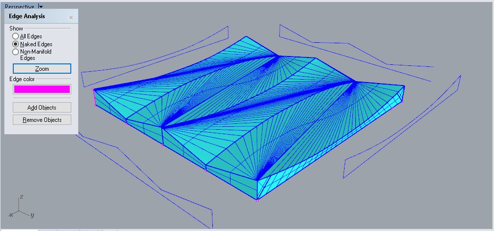
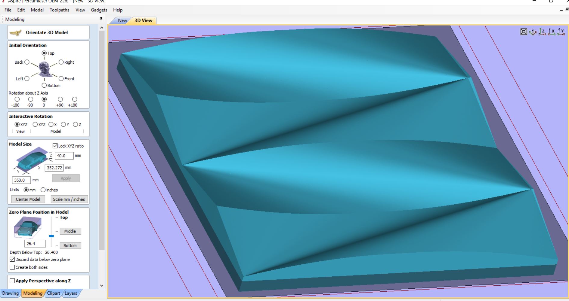
Once I had both surface ready, I needed to have a closed mesh and get ready for Aspire to make the adjustments needed for the CNC Machine.
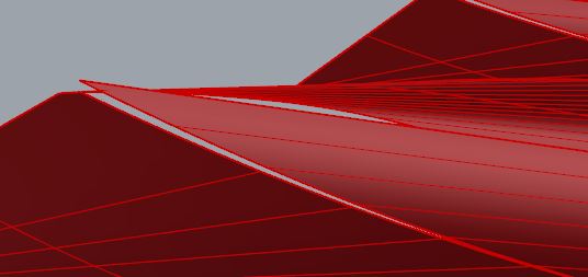
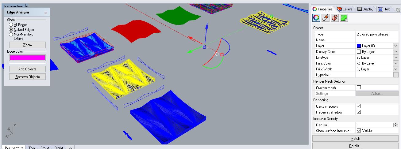
Problems While Designing - Closing The Mesh
The main problem I had to create my mesh was to actually close it! What I did was to play on
Rhinoceros with different commands to see if they closed the mesh, but most of them I was unlucky.
First I tried to use the command: 'Silhouette' from a surface, to use those curves to build the different planes on the perimeter.
It did not work.
The I used all the different commands on Rhinoceros: 'Loft', 'Planar Curves', 'Sweep 2 Rails'
(this one helped me to close one of the meshes), 'Surface from Planar Curves' , 'Surface from Network
of Curves', 'Surface from 2,3, or 4 edge Curves', 'Patch', 'Extrude Straight' from a surface (this did
not work too).
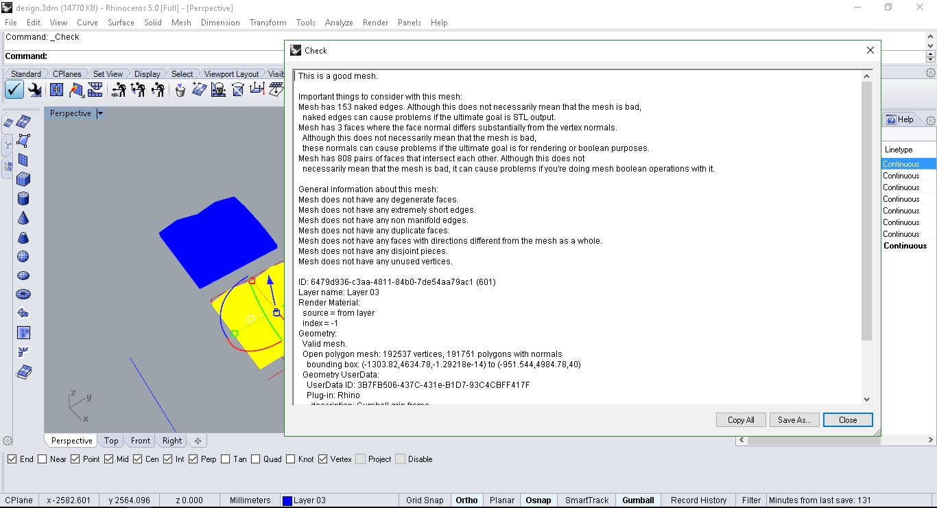
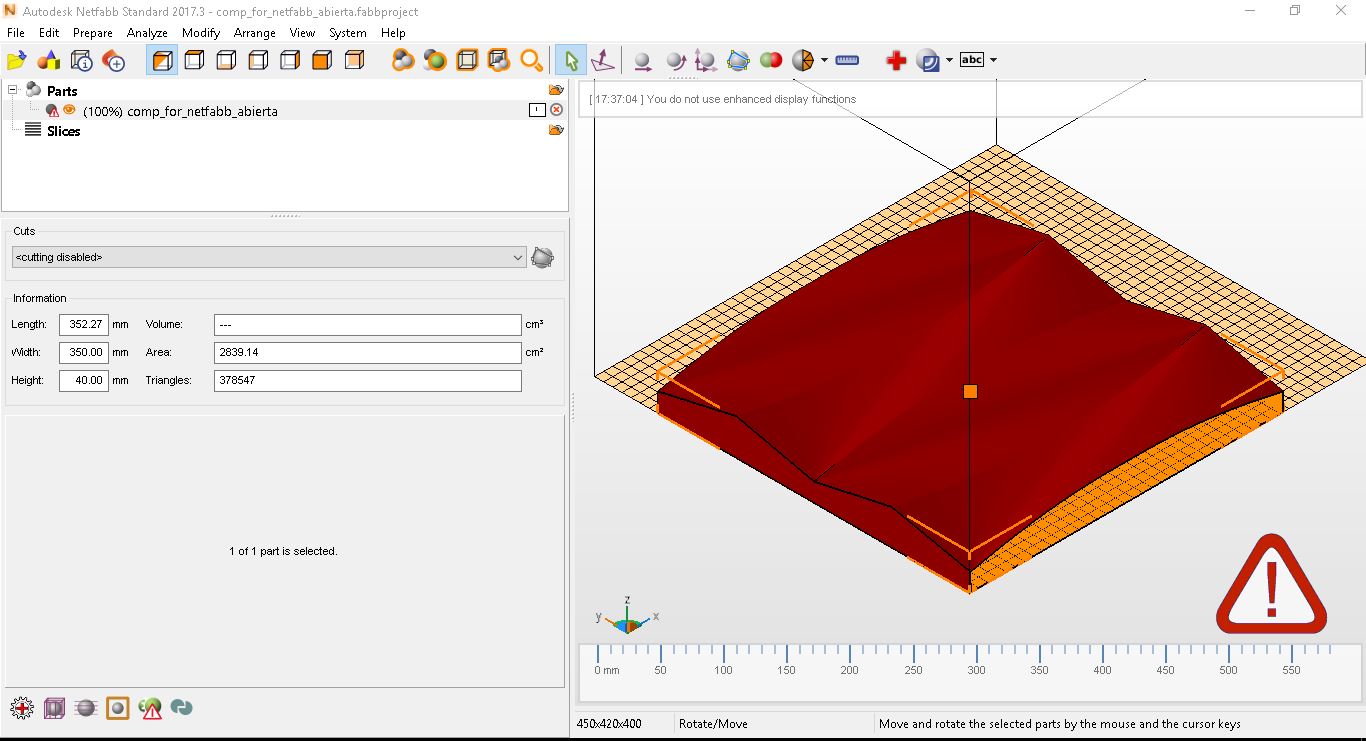
In the end, I spoke to my instructor and helped me by installing Netfabb from Autodesk and closing
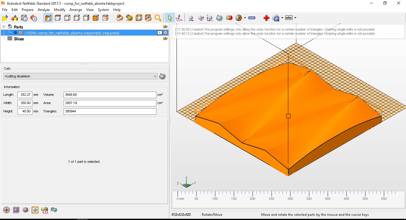
the mesh in a few minutes.
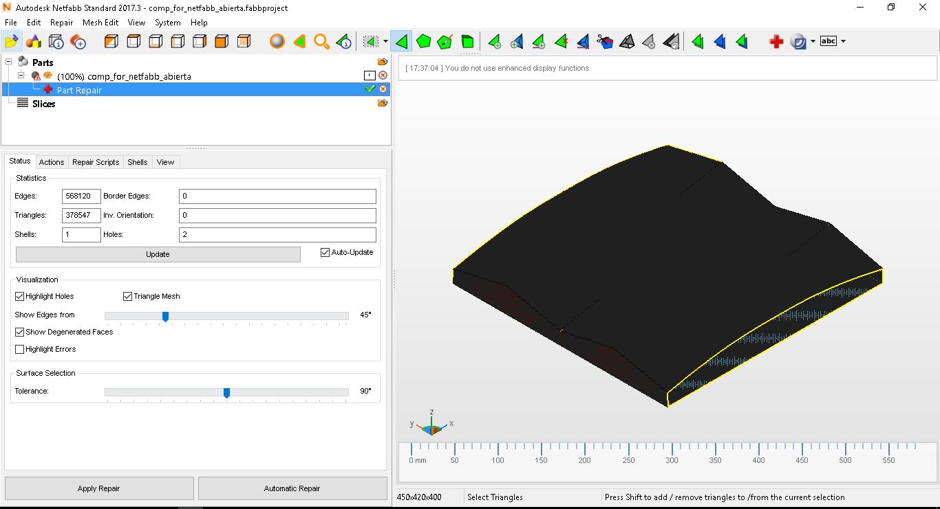
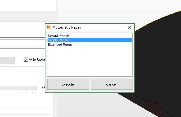
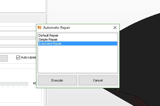
In red = mesh not closed, with a sign alert at the low right hand side corner.
Press command ' Part Repair', and 'Automatic Repair'--> 'Simple Repair'. It helped, but still it did not close the mesh. Then, I selected 'Extended Repair'.
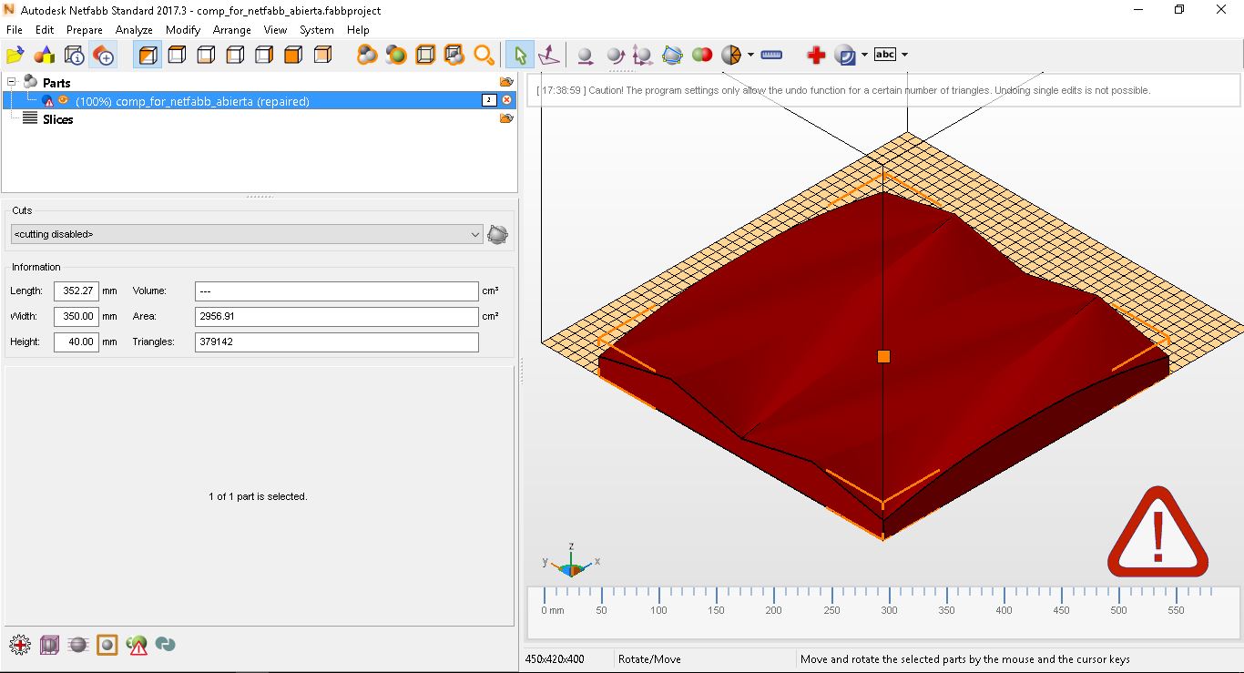
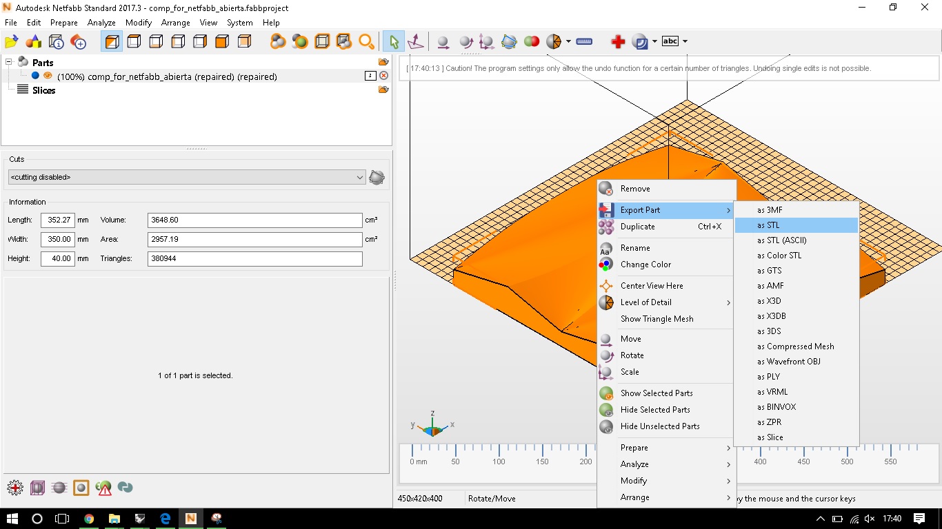
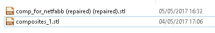
The mesh turned orange as it was closed, export as STL and get ready for the CNC program.
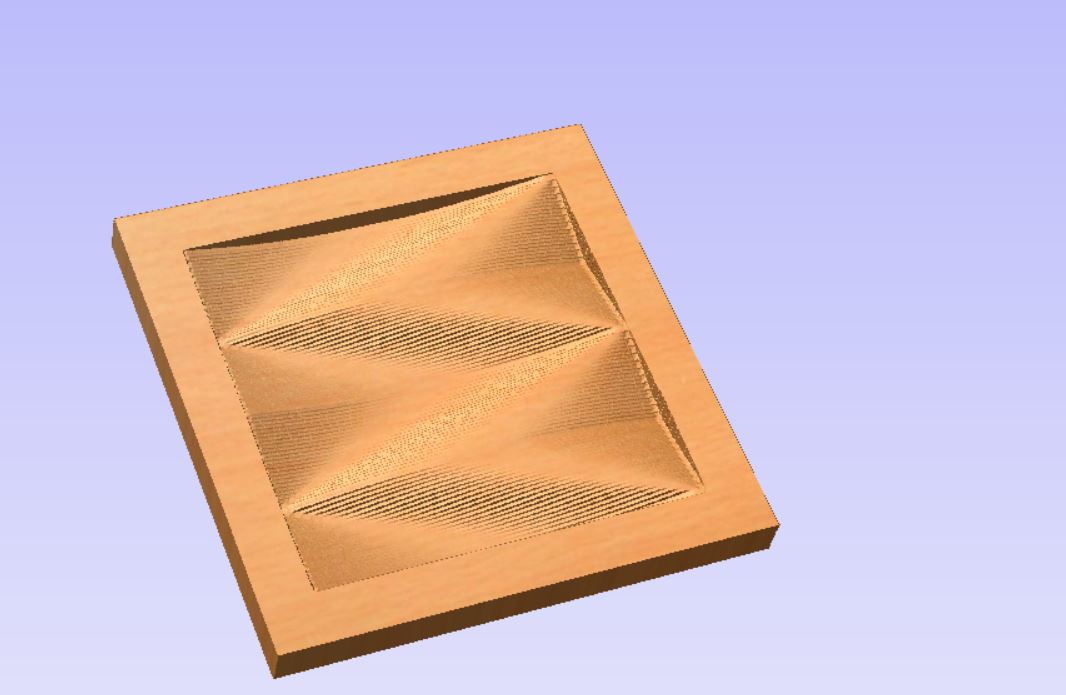
This is the final result once done all the adjustments that need to be done for the CNC Machine:
Introducing the stl file to Aspire. Adjustments made:
-Job size: 450x450mm (my design is 350x350mm)
-Zeroing at the bottom
-Thickness: 40mm
-XY Datum at the bottoom left
-Units: mm
-Modeling Resolution: Very High
Now it is time to import my stl file:
-Modelling
-Import
-Centre Model
-At the Bottom
OK!!
My file is imported successfully, now it is time to create a perimeter vector around our model
for the program to read what exactly needs to handle when calculating the milling. I got to the
2d section and create the vector. With the vector selected, we go to the milling adjustments for
the material setup.
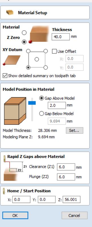
As most of the adjustments were done before, I only had to change one of them and check the others were
correct. In 'Model Position Material', I decided to have a 1.0mm layer 'Gap Above Model', to make
sure the top layer once the piece is milled is completely horizontal.
As most of the materials used has a variation of several mm in thickness, this is a nice way of preventing these variation in our piece.
Material Setup:
(Material)
-Z Zero: at the bottom; Thickness: 40mm
-XY Datum: Bottom Left
-Use Offset: NO
(Model Position in Material)
-Gap Above Model: 1 mm
-Model Thickness: 28 mm
-Model Plane Z: 1 mm
-Rapid Z Gaps Above Material: Clearance (Z1): 6 mm/ Plunge (Z2): 6 mm
-Home/Start Position: 0, 0 ,56 (Home)
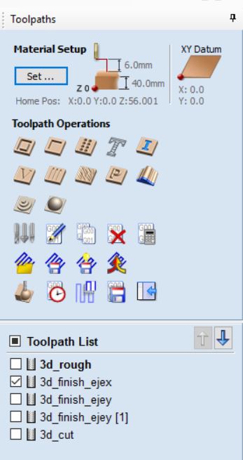
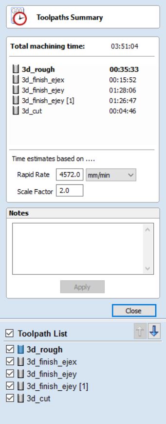
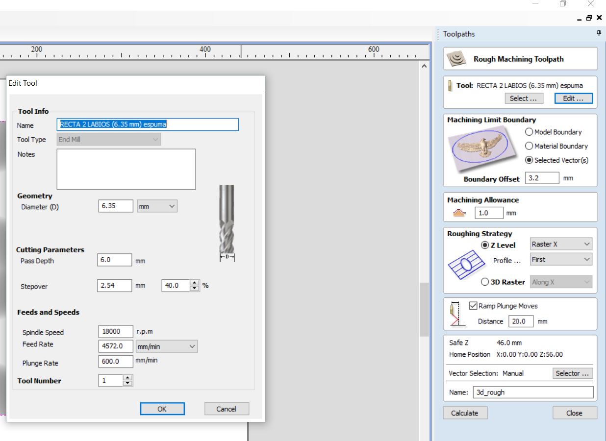
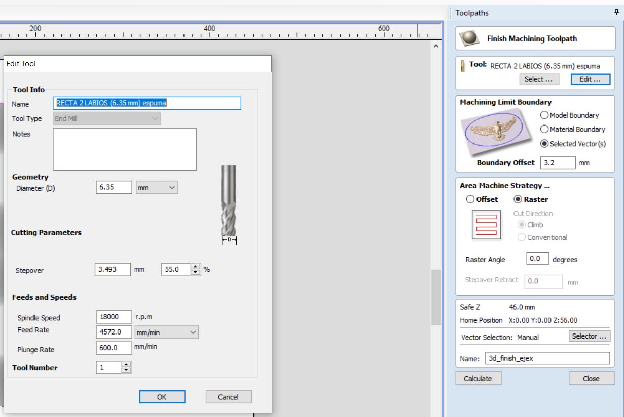
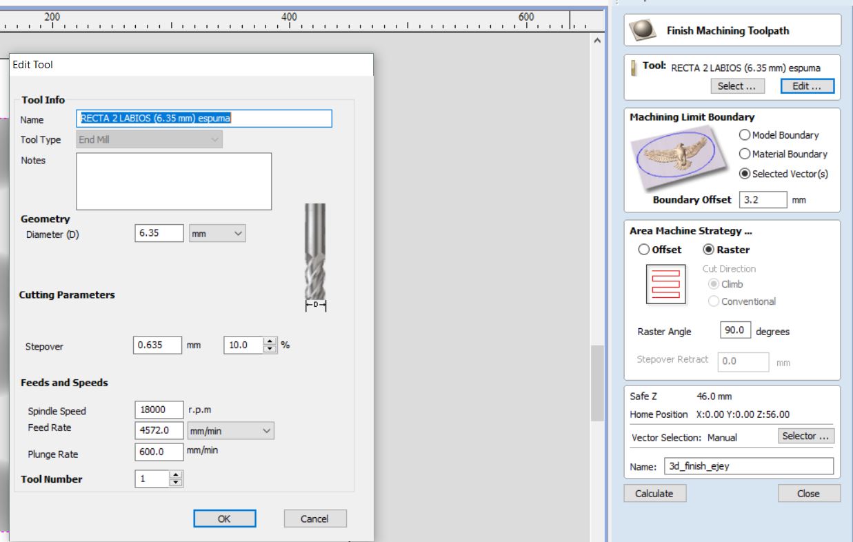
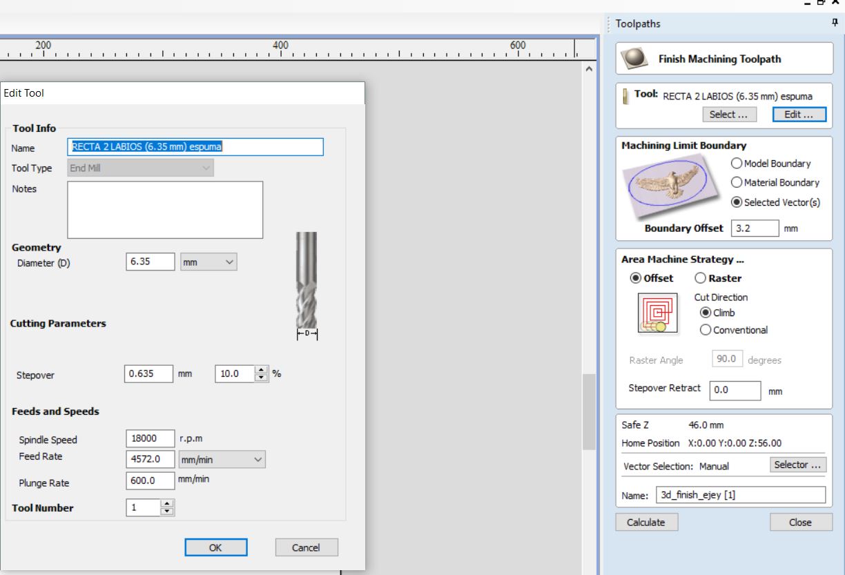
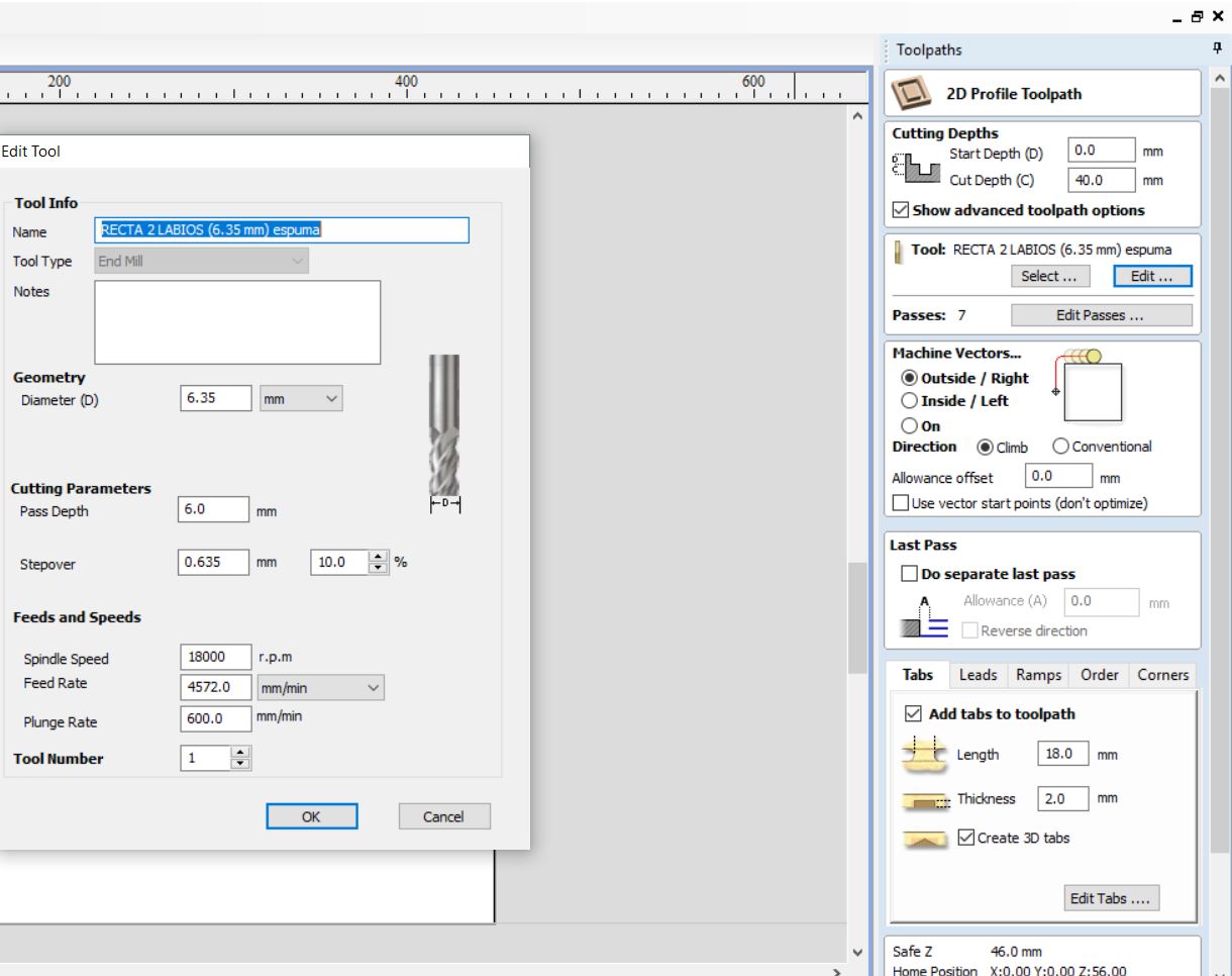
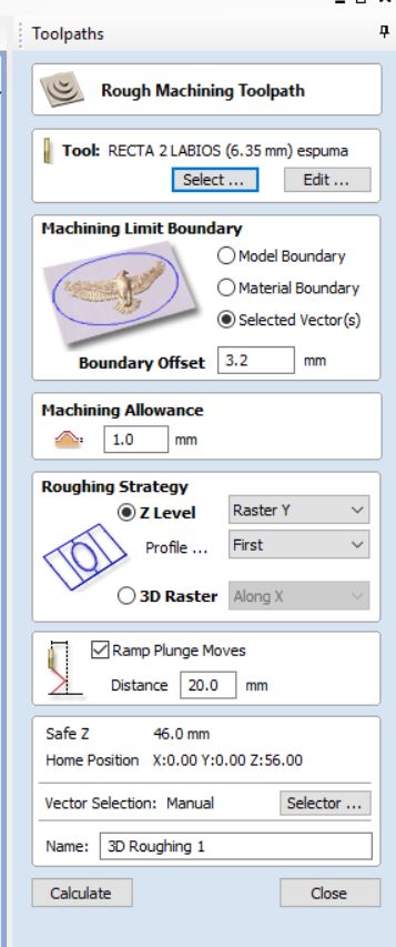
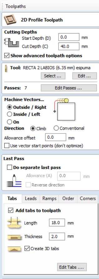
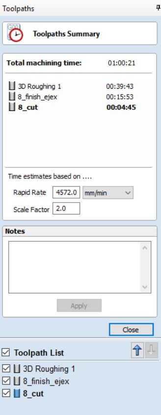
Now it is time to create my Rough Cut, my Finish Cut and the Final Cut. On the picture below, I wanted
to compare how much time does it take to mill on the X axis and Y axis with different parameters.
The main differences between them is in one hand, to see which axis was better to mill with depending
on my design. On the other hand, as we are doing composites, any details on the finishing cut of the
mould will not come out on the final result, therefore, I wanted to modify the step over to see how much
time can be saved without giving up the purpose of my design.
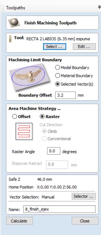
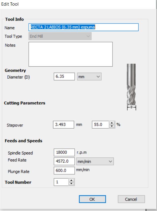
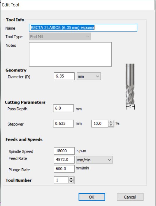
As shown on the picture below, I have the 3 different finishing cuts. The adjustments made are:
-3d_finish_ejex(X axis): has a step over of 55%.
-3d_finish_ejey(Y axis): has a step over of 10% with the raster parameter.
-3d_finish_ejey[1](Yaxis): has a step over of 10%, with the Offset parameter with climb.
As we are doing a Composite, the finest details of my mould are not going to be shown on the finished object.
Therefore, taking a look at all the possible options, the difference between a finished cut with a 10%
(very detailed) with a finished cut with a 55% stepover, is very little. Although on the mould it will
be very clearly visible, changing this parameter allows me and my fablab saving a lot of time without
having a negative impact on my final composite. Instead of having one hour and a half of finished cutting,
with 15 minutes will be enough to finish with the same detail on the final object.
After discussing this with my instructor, I had green light to do as mentioned above.
The following images show the different parameters used on each type of cut (rough, finish, perimeter cut):
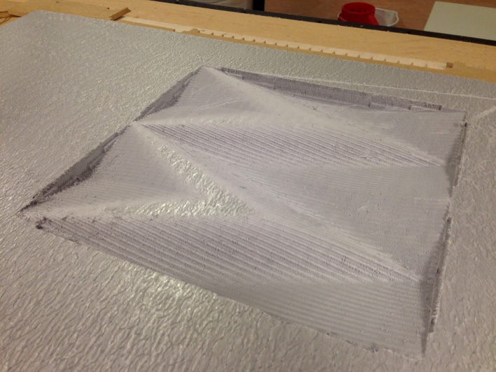
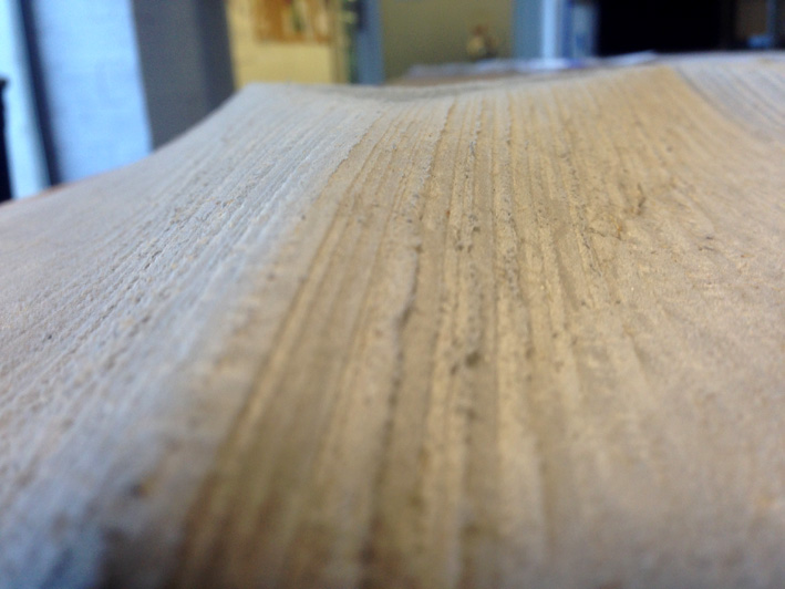
Top Side Of The Mould - After 3d Finish Cut X Axis
The same adjustments on Job Setup as before
(same parameters as before)
Creating the boundary vector of my model
As my model was higher (h=42.8mm) and the material used had 40mm at the most, instead of using
the whole height of the model, I reduced it to 25mm tall.
Same material setup as above, with the difference of having a 2mm top layer, as the 1mm layer did
not work as expected.
For the adjustments, the same as the other part of the mould. Rough cut a step over of 40% and the finished
cut a step over of 55%.
Total machining: 1 hour. Before the adjustments made, that would have been of 3-4 hours each part.
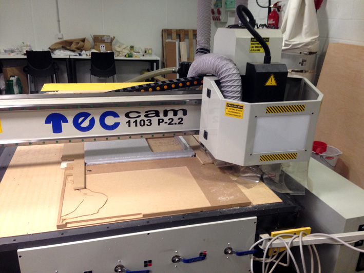
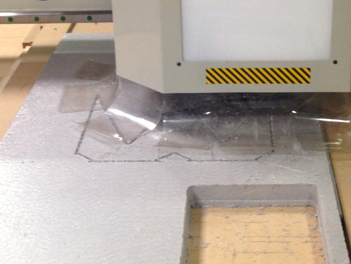
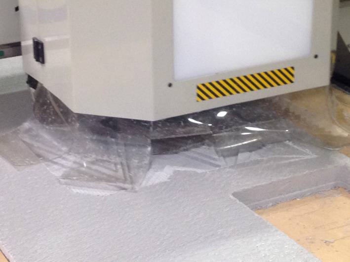
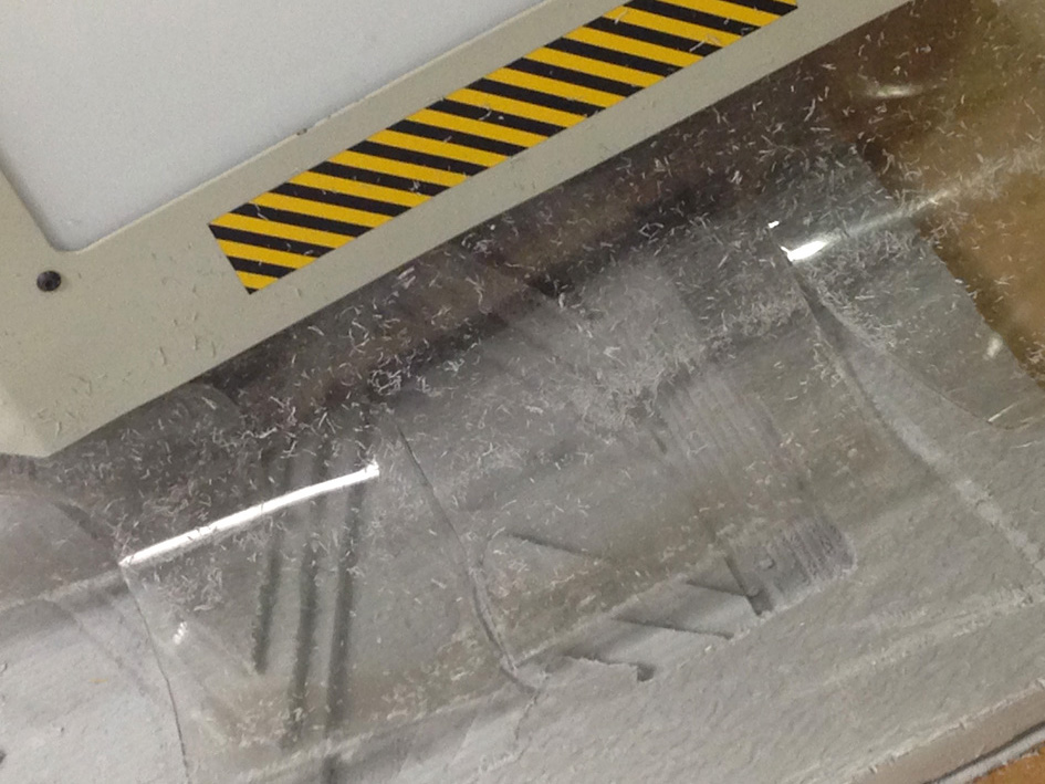
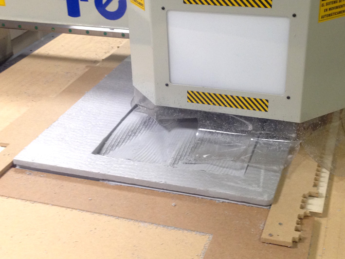
CNC MACHINING: RESULT
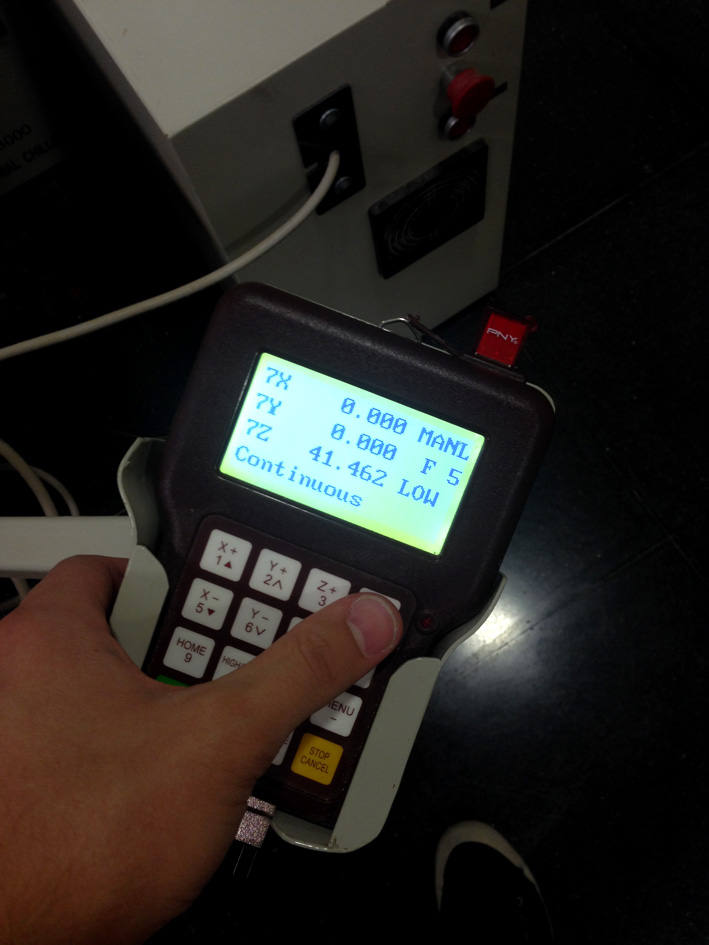
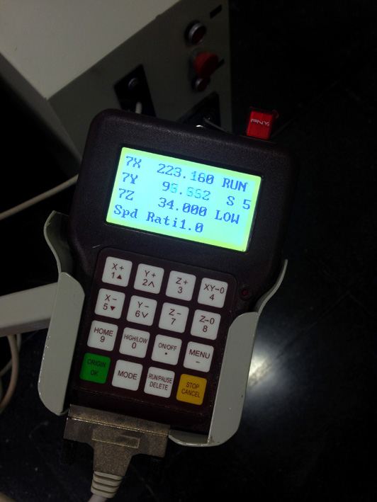
Once I have my file ready, I save it in a USB Pen drive and ready to plug it in into the machine.
Starting the 'Finish Cut - X Axis'.
Making the adjustments needed explained in 'Week 7 - Computer Control Machining' (go to website).
Let's start milling!
Starting with the 'Rough Cut':
Continuing with the 'Finish Cut - X Axis'
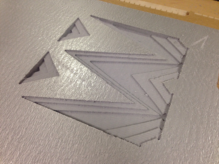
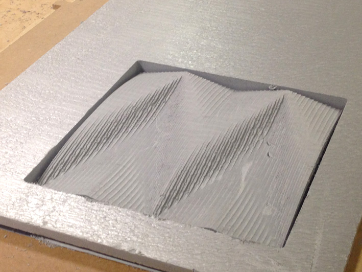
Both Moulds After Finish Cuts
Finishing with the 'Perimeter Cut':
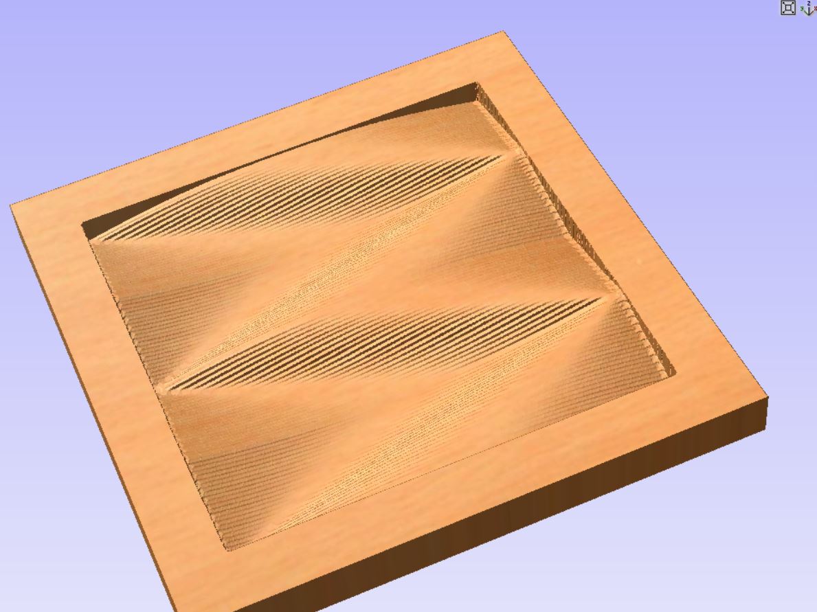
Final Result - The Mould
(open-closed mould)
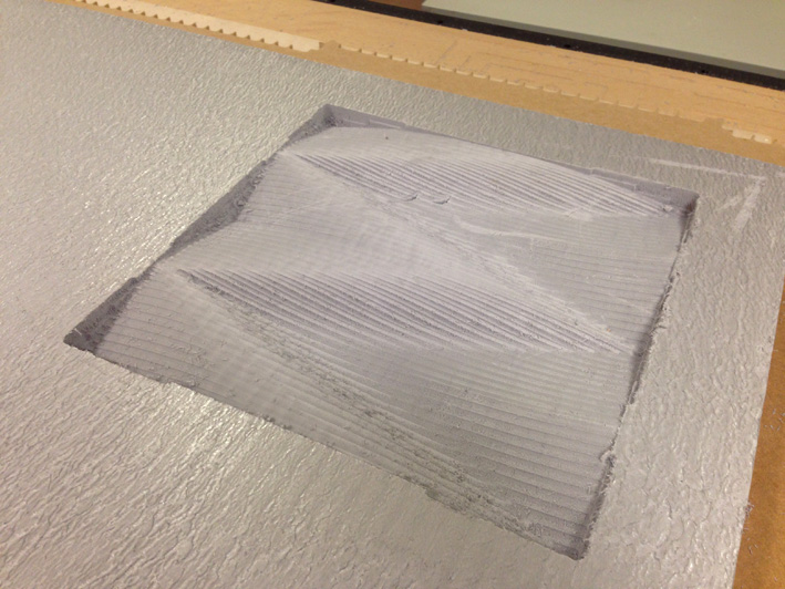
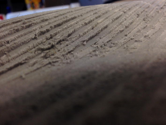
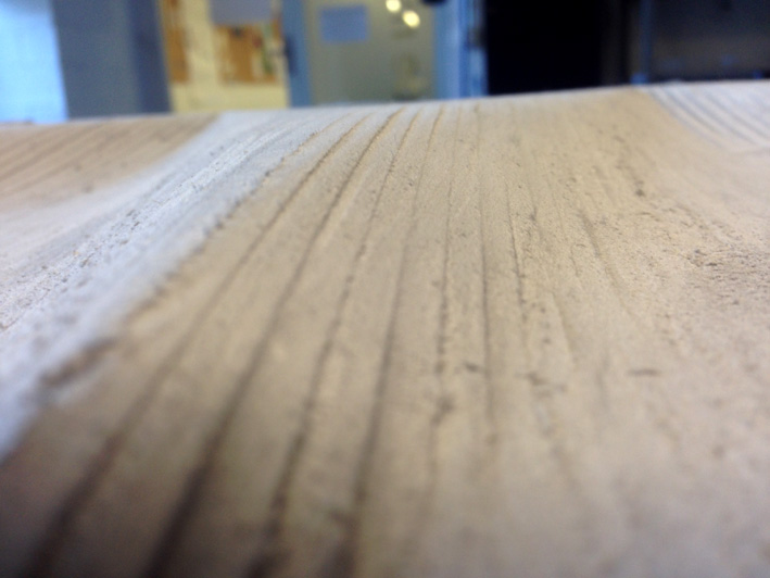
Small Issue
As before I gave some finish quality over the mould to save up to 2 hours of cutting time, some minor issues aroused when
taking a look to the 'Finish Cut' of both moulds.
Having a close-up to the finish quality of the mould, I just had to sand a little the surface to have a smoother
surface.
If I would have not sand, I think that the results would have been the same or almost the same. On the other hand, I just
needed 10 minutes to sand everything. Minor issure = quick solution.
9. MY COMPOSITE - PHYSICAL MOULD + NATURAL FIBRE
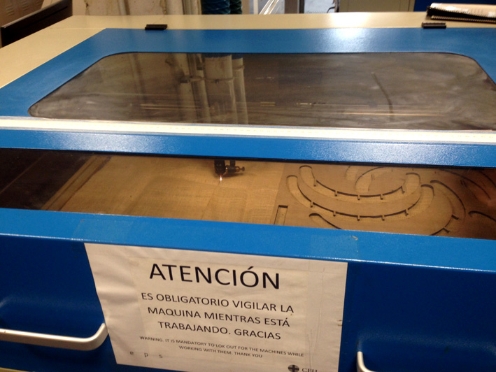
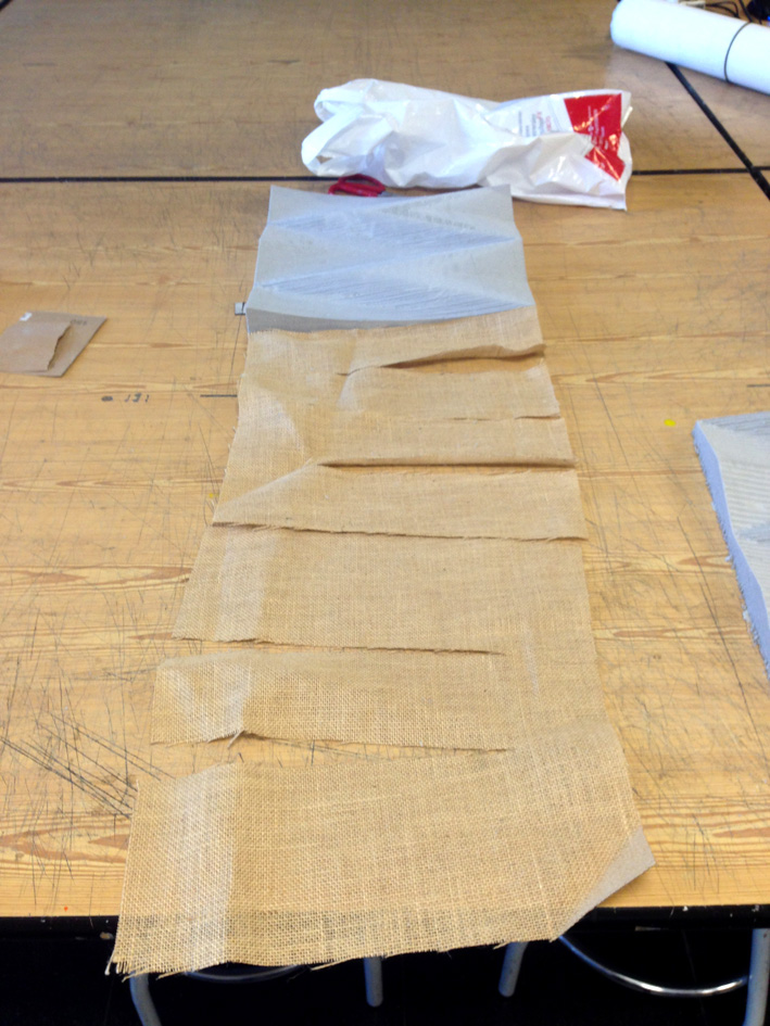
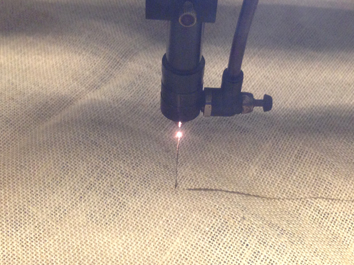
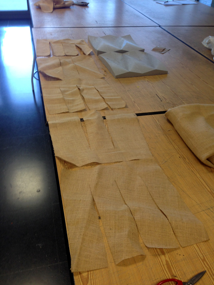
Preparing The Natural Fibre With The Lasercutter Machine
Going back to Rhinoceros, I selected my object and selected the command: 'Developable Surface', so my 3d turns into a 2d cut material.
As my object has different slopes, an excess of material would appear on those parts where the inclination varies.
Developing the 3d surface in a 2d plane assures me to handle this excess of material with precision.
Now, changing it to .dxf 2004 and into the Lasercutter machine program:
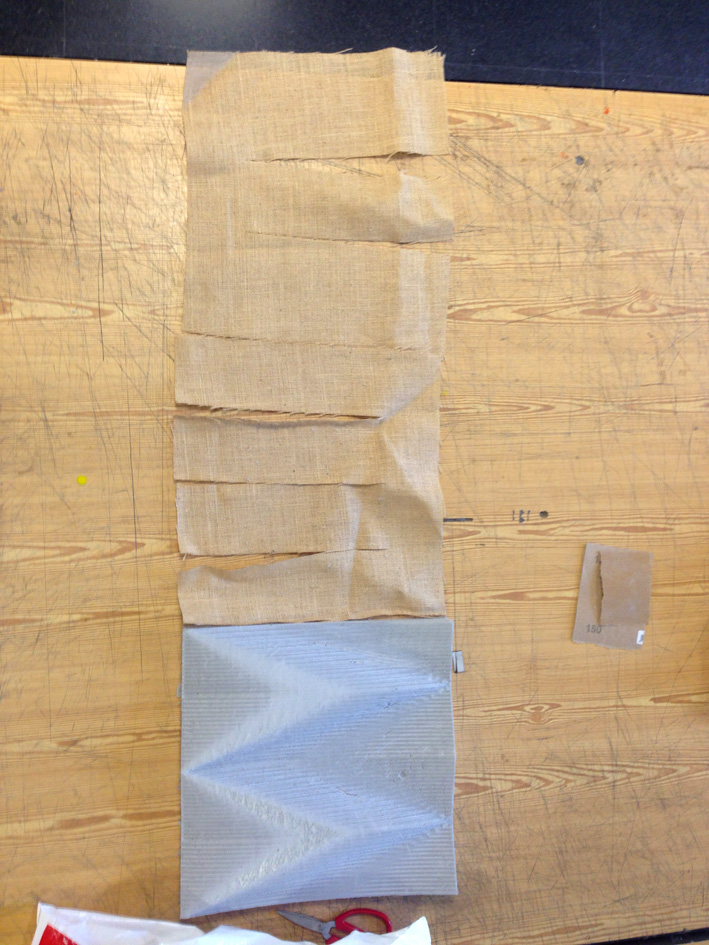
The idea is, continuing with the design the first developable surface has, create an opposite surface that has two
main goals that is placed the opposite way as the first one:
-Make sure the 'legs' of the developable surface is correctly tighten up
-Its fibres being at 45 degrees, interrelating direction to make sure a good grip + tension resistance is assured.
The following video shows how is going to be done:
Printing 3 More Layers Once I Made Sure Is Correct
Cutting 'Developable Surface 2' at 45 degrees.
Everything Together
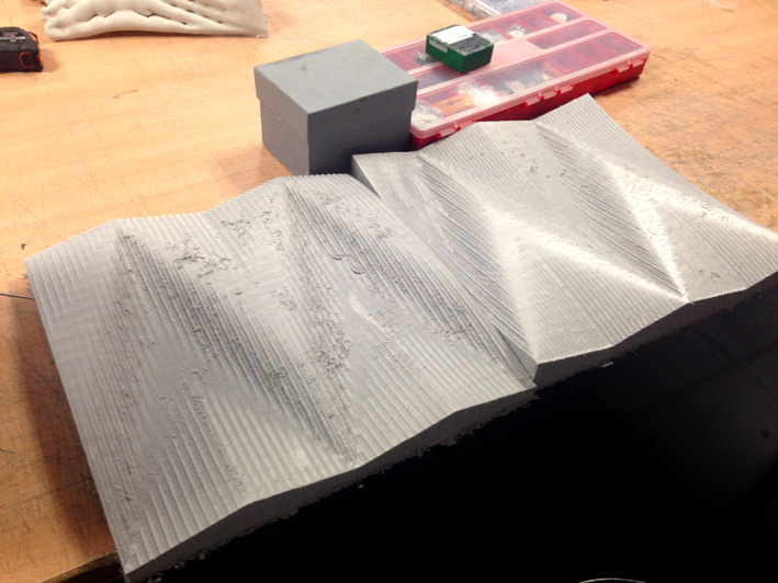
10. My Composite - Building It
Following the same method as with the coupon, I continued on building my first composite:
Preparing The Material
Calculating Volume Needed Of Resin With Water + Scale
I needed to know how much volume the piece had + the conclusions I had previously while doing the coupon and comparing
with my colleague's results:
Total Volume Needed:
As I will have 5 layers and not 10 as done with the coupon, if each natural fibre layer is 0.6mm and I have 5,
it gives a total of 3mm height of total material.
Volume = 40cm x 36 cm x 0.3 cm = 432 cm3
This time, I decided to go back and use the recommended ratio 50:50 as I had an excess of material:
Volume that corresponds to Resin:
432/2 = 216cm3 of resin.
Now, to make sure I do not run out of resin during the process, I increase this quantity by 20%:
Total Resin Volume Needed: 260 cm3
Now, on the GreePoxy Data Sheet (botón al data sheet), the ratio is 100:47 (resin epoxy : SD).
For Resin Epoxy: 177ml
For SD:83 ml
Once I measure the volume with the water's weight, I taped the plastic cup to know exactly where the amount of resin
has to stop.
Let's start!
Vaseline On The Plastic Film Of The Mould's Protection
Compressing The Mould
One Day Later
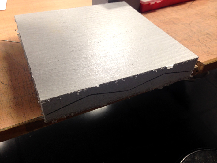
11. My Composite - Final Result
Composite's Detail
12. Problems Accounted
Coupon
Using that quantity of resin is a problem, but the idea was to experiment with it and compare the different results with the other coupons made from my colleagues.
The conclusion:
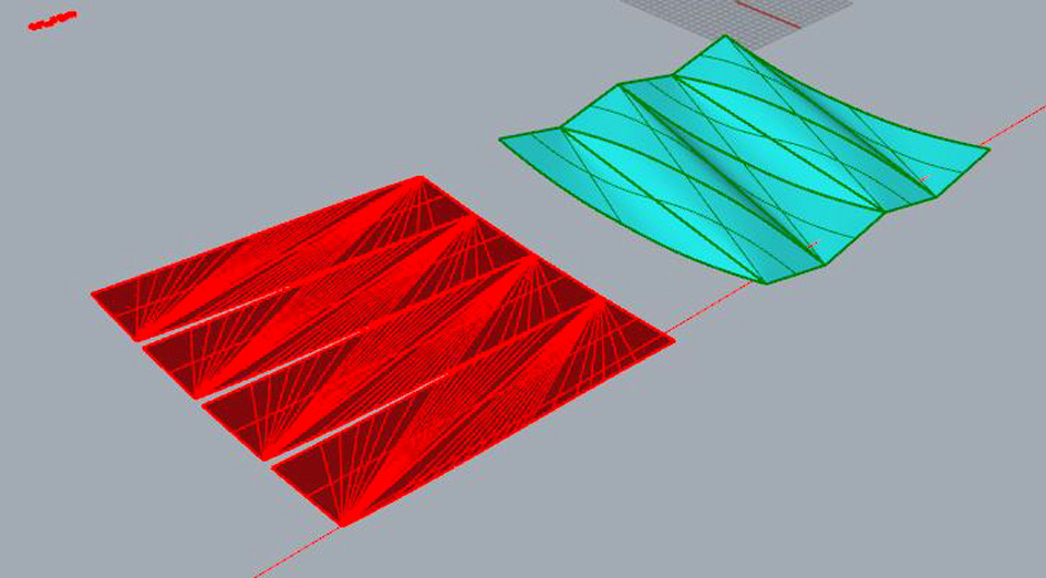
Closing Meshes
As I have a two-sided mould, I had problems closing the mesh of one of them. It took me a while until I had it ready
to import it into V-Carve (CNC Machine Software).
Taking a close look to both meshes (just below), while the first one has a nice clean mesh made out of 50 000
polygons, the other one is uglier made out of nearly 500 000 polygons. This big difference has to do the way
I closed it using Rhinoceros and Autodesk Netfabb (everything explained above).
Fortunately, once finished closing it, it did not give any more problems.
Milling The Physical Mould
Although this situation was not a problem, it is worth talking about it. At the moment of adjusting all the
parameters needed on the CNC Machine, there was a big difference milling for 5 hours rather than for 2 or
3 hours.
Discussing with my instructor which option was the best considering that I was doing a composite and not
a perfectly detailed object, we decided to go for saving time with both reducing the overlap and only in
one direction.
Detailed Explanation:
Sanding The Mould
This is directly related to the situation above, reducing the overlap and milling the finish cut only in one direction
let to have a nasty surface.
Considering I only sanded the surface for only 10 minutes until I had a nice smooth surface. I think it is a good
move as my instructor and me analysed all different situations and possible results, choosing the best one
in terms of time, quality and results.