Procedure:
0. Assignment
1. The Idea - Furniture.
2. Tests.
3. Computer Aided Design.
4. Getting Ready to upload the file to the machine.
5. Process (Cutting & Building)
6. Final Result
7. Final Joints
8. Further Analysis
9. Download Files
0. Assignment
Make something big (on a CNC Machine).
LEARNING OUTCOMES
Document the process of design and production to demonstrate correct workflows and identify areas for improvement if needed
HAVE YOU...
...explained how you made your files for machining (2D or 3D).
...shown how you made something BIG (setting up the machine, using fixings, testing joints, adjusting feeds and speeds, depth of cut etc).
...described problems and how you fixed them.
...included your design files and ‘hero shot’ photos of final object.
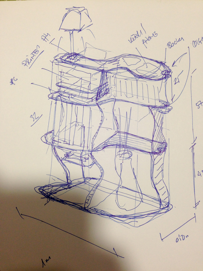
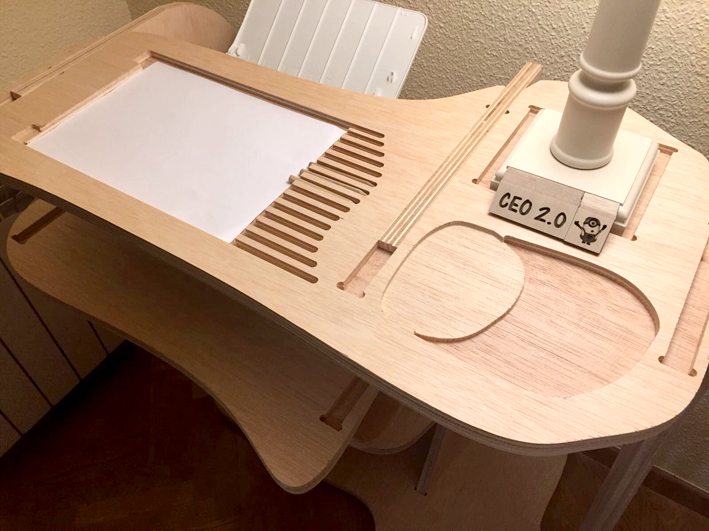
1. The Idea
The whole idea is to create a piece of furniture treated as a 'headquarters' organiser that solves
the different issues related to organising oneself at home. The material that we are going to use
is Plywood 20 mm thick.
The goal is to have enough space to gather all the different objects one needs at home.
The objects are listed below:
-Laptop
-Books
-Big Folders
-Lamp
-Car/House Keys
-A4 Printer
-Router
-Plant/Decorative Elements
-A4 Paper
-Pen/Pencils
It is important to mention that this piece of furniture will not have any screws or vessels while
it is build. The idea is to have a clean wood joint.
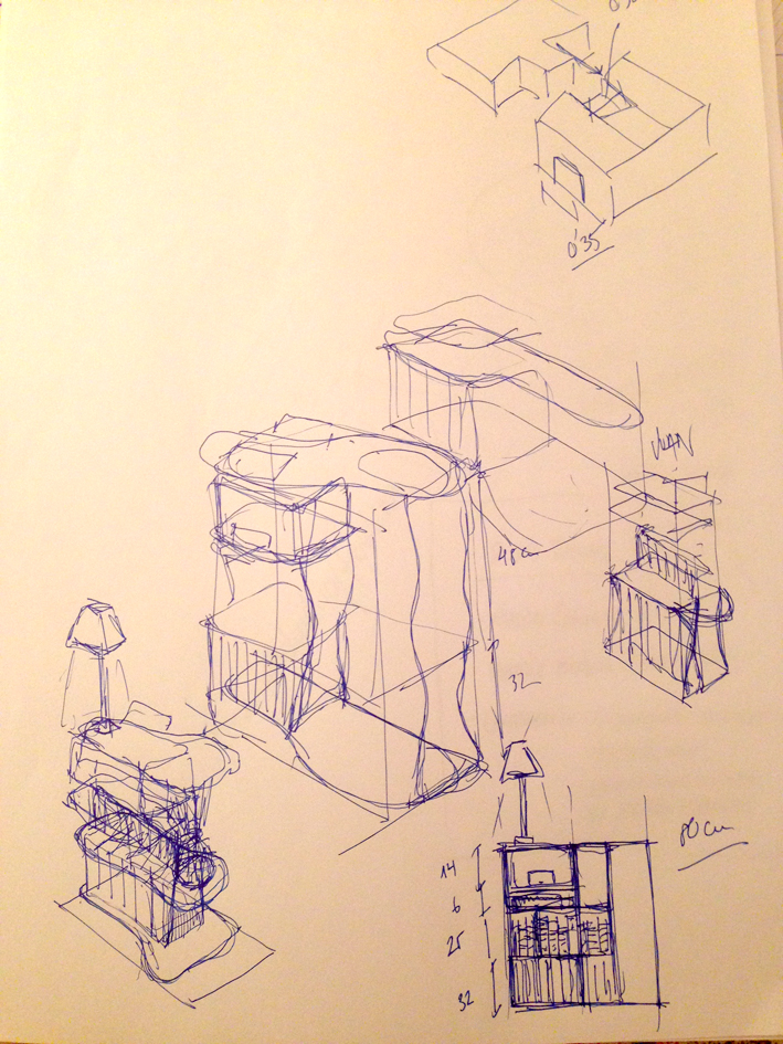
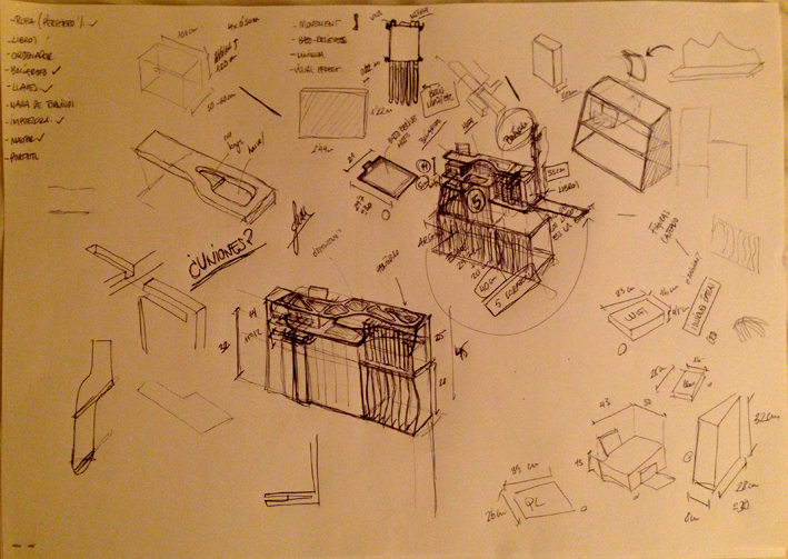
Here we can see a different sketch of what I am looking for:
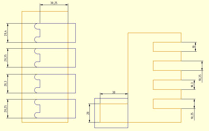
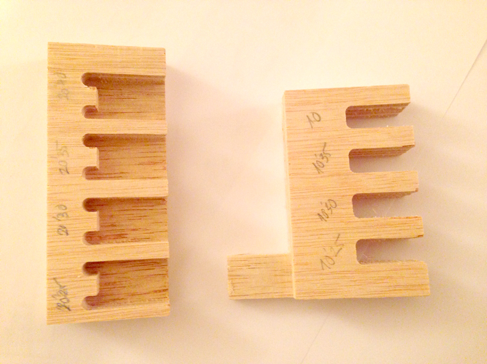
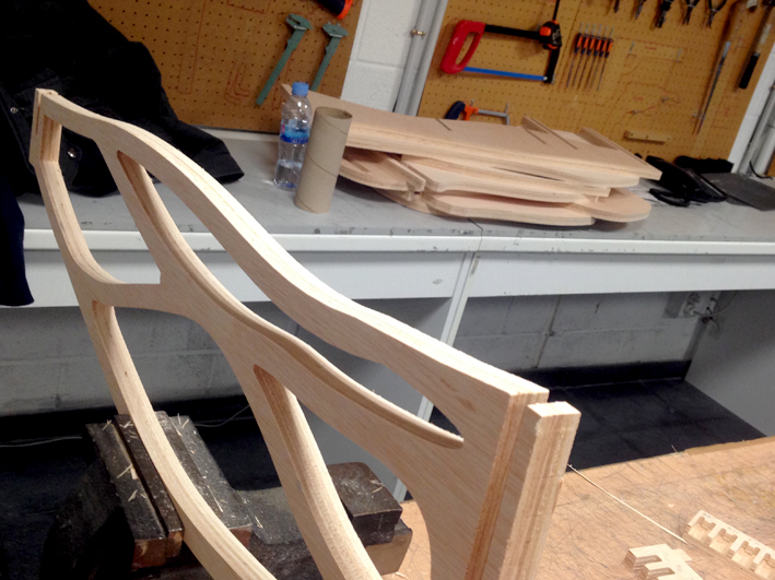
2. Tests
Before cutting the real thing, I wanted to make sure that the join type that I am using is correctly
done. As I am not using any additional elements for the joints, these needs to be done carefully.
What I wanted to test were which tolerances are the best to have, accounting both height and width
as it is a 3d joint. Therefore, the minimum width I designed was the one our instructor told us: +0.25mm.
Each hole has a variation of 0.05mm upwards (20.25mm, 20.30mm, 20.35mm, 20.40mm) for a 20mm match.
On the other hand, for the height I am using the same strategy, but with a 10mm match.
Here is the document:
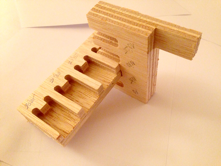
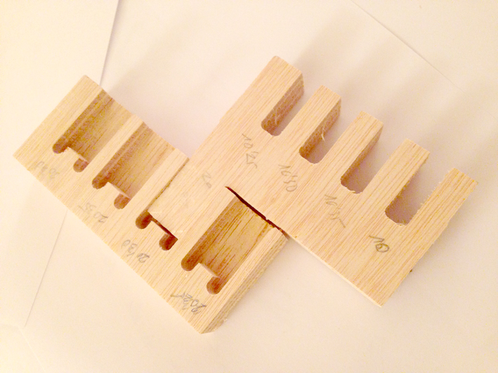
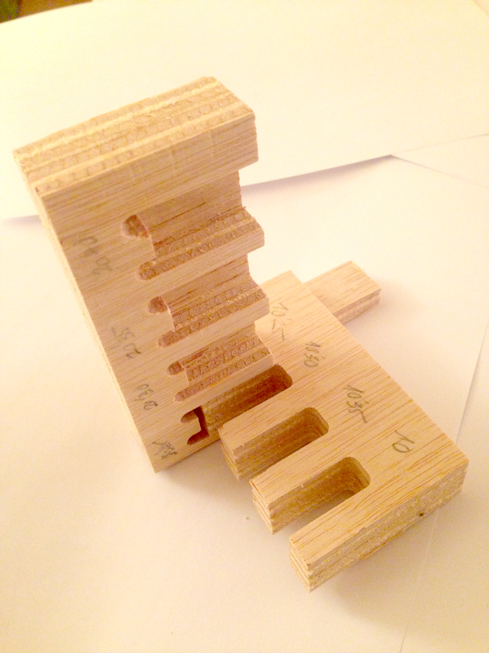
Conclusions:
The minimum width and height matched correctly, but it was kind of difficult to put it together.
As I am going to have longer joints, it is better if the joint is more loose.
Tolerances that I am going to use is: +0.40mm.
3. Design
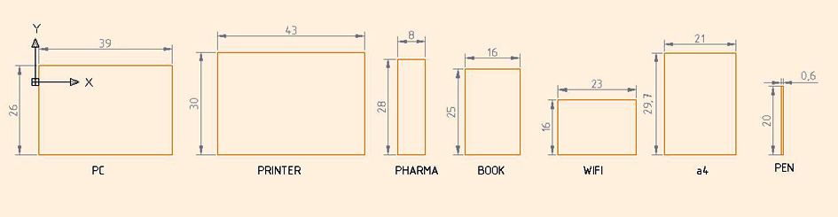
Measurements needed:
While designing the furniture, I did 3 different designs, but unfortunately I cannot show the
first 2 designs as I forgot to save them while doing it. The main problem I had was that I
exceeded the amount of material available to cut, so I had to rearrange everything in order
to fit it correctly.
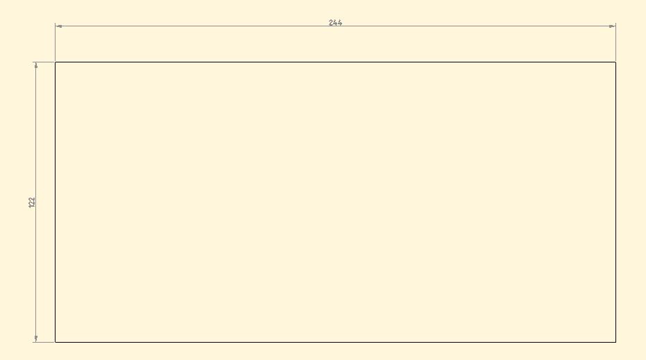
Plywood 20mm board: 244x122cm
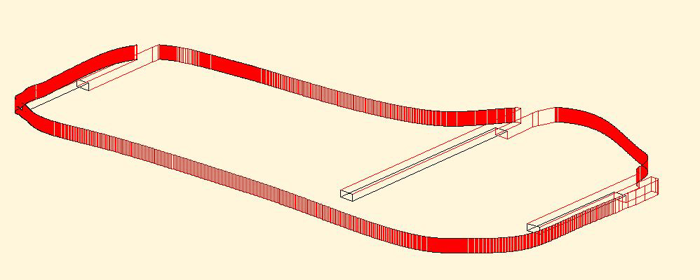
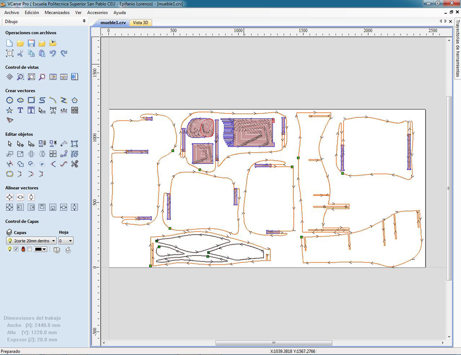
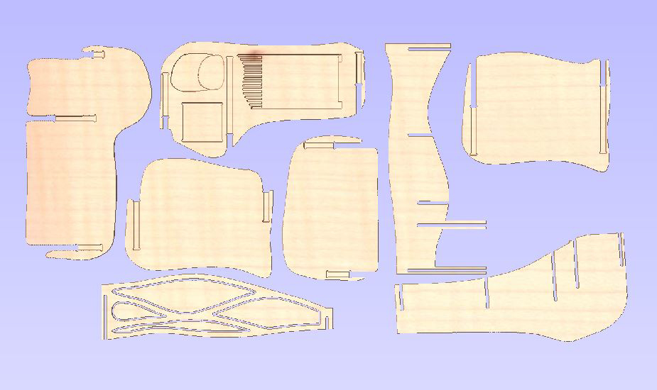
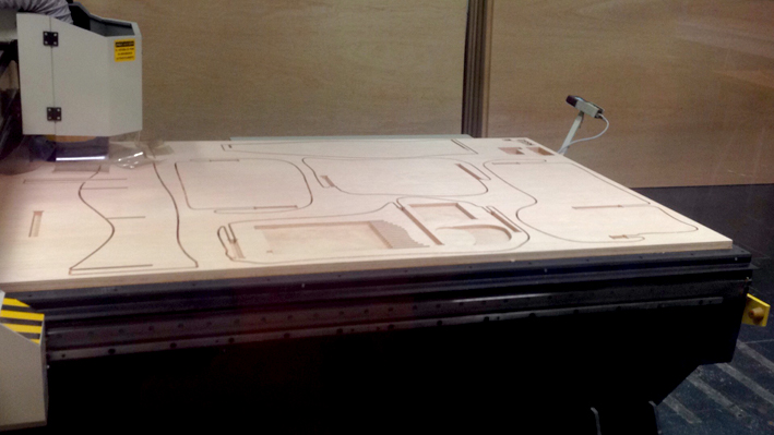
My board layout:
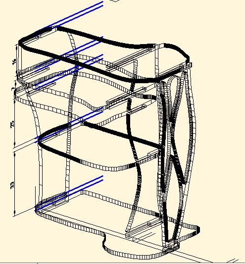
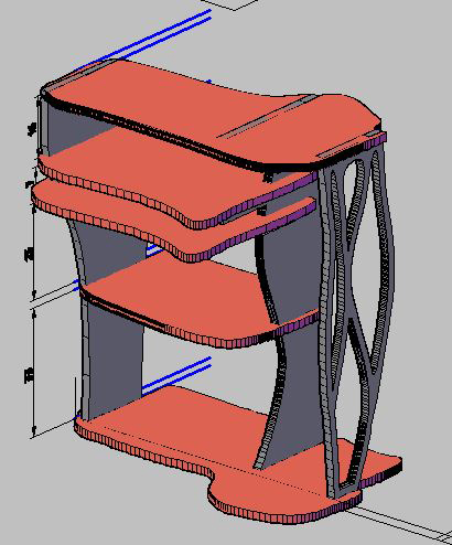
Red: cut depth of 5mm;
Blue: cut depth of 10mm;
Orange: complete cut through the board
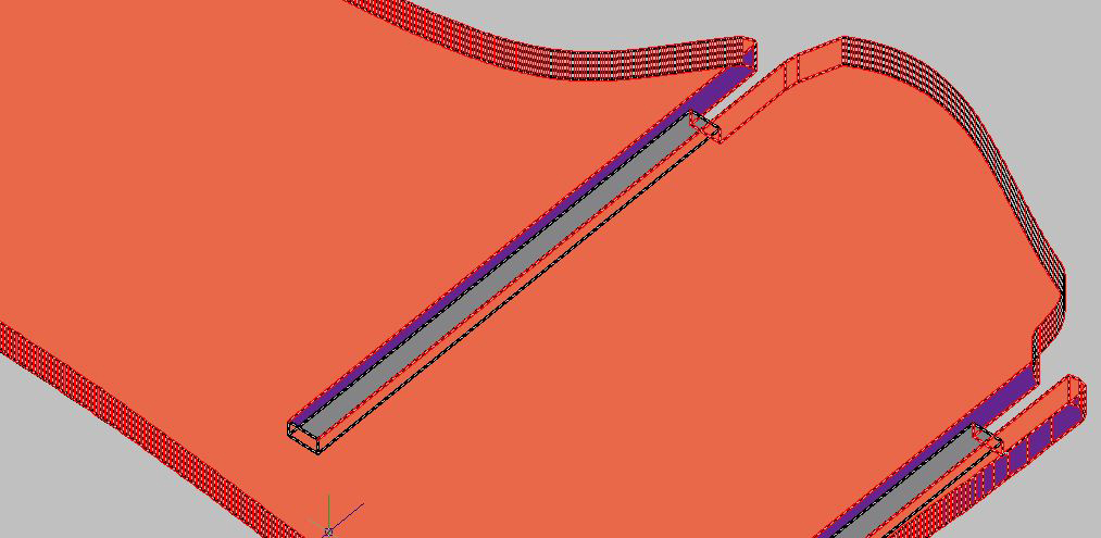
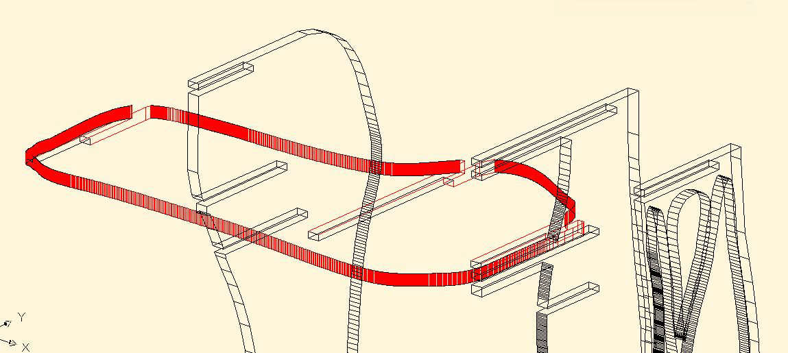
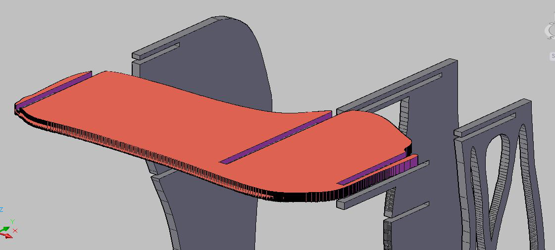
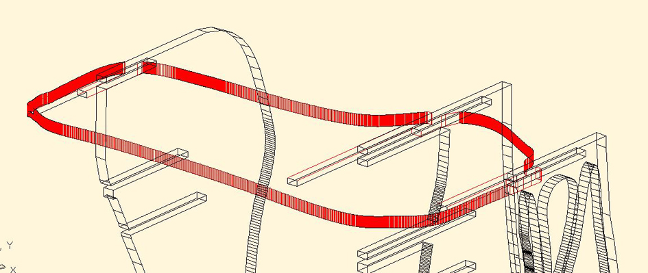
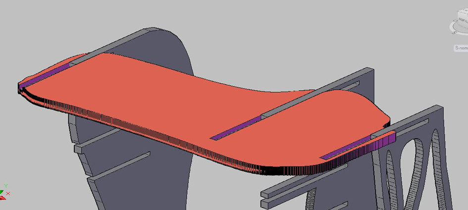
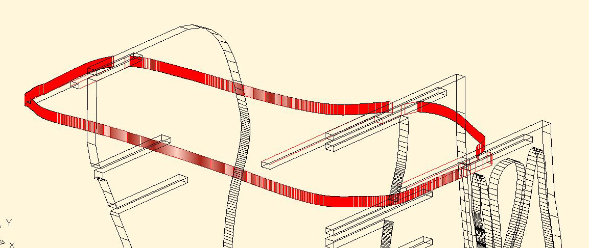
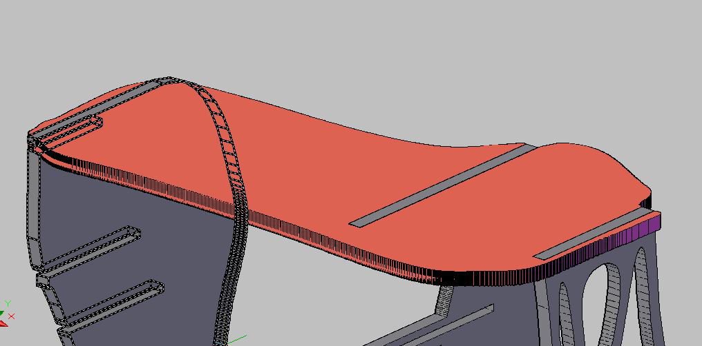
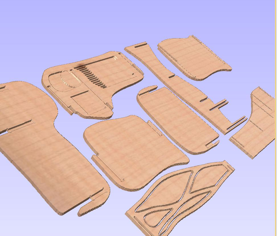
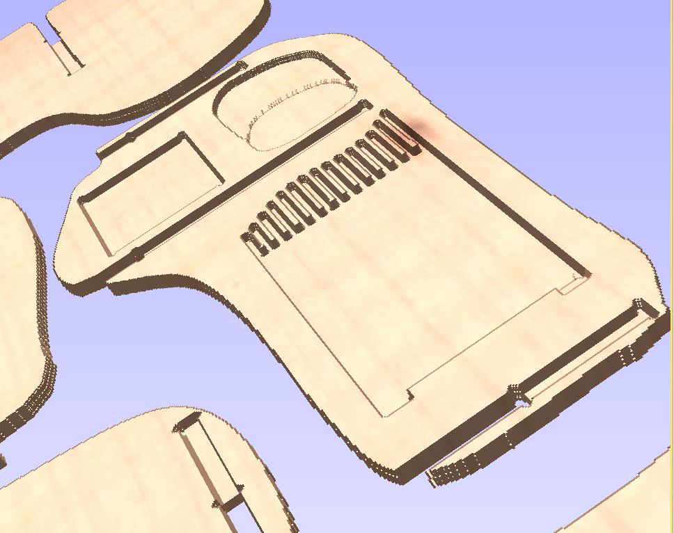
3D VIEW (the 10mm depth layer is not showed in this image)
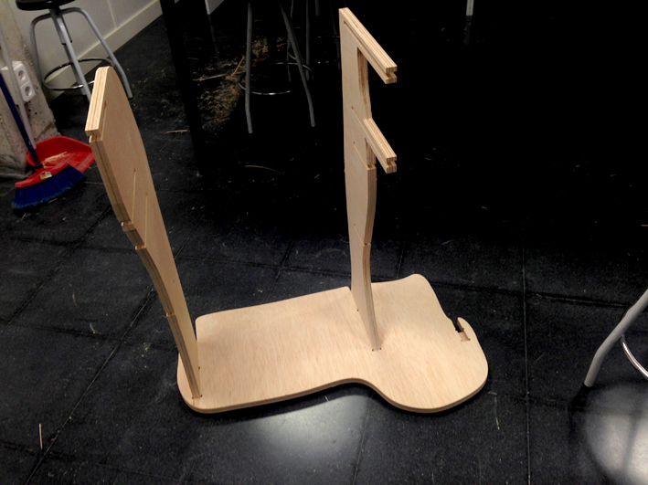
The vertical structures hold to the horizontal shelves.
Process: how the joints come together: Sliding one horizontal board into the vertical structure
4. Getting ready to upload the file to the machine
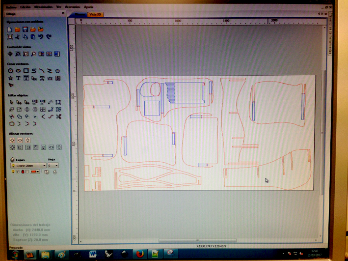
A very important step is to adjust all the parameters to my design. First, importing my 2004 dxf file
into vCarve (CNC machine's software):
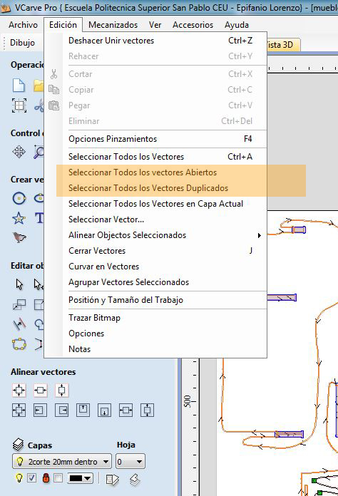
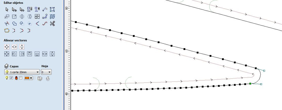
Checking there are no duplicated vectors nor opened vectors:
I had two vectors that were not correctly done on my computer. I needed to change them so they
will be cut correctly.
Tool used: line tool and selection tool. All the t-bones were done before exporting to this program.
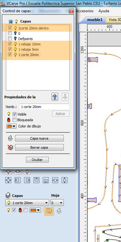
Opening my layers+adjusting mill's parameters+ configuration
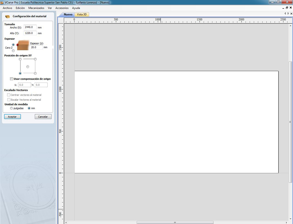
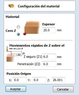
-Material configuration + zeoring correctly on the sacrificial layer:
-thickness: 20mm
-Zero Z: on sacrificial layer and manually once the file is uploaded to the machine.
-Zero XY: (0,0)
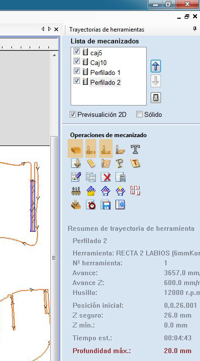
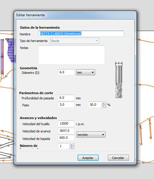
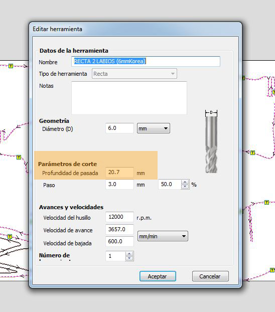
Endmill I am going to be using:
-Diameter of the endmill: 6mm
-Type of cut: up cut
-Endmill type: Flat end
-Number of flutes: 2
-Speed: 12000 rpm
-Cut depth: 5mm, 10mm, 20mm.
-Depth cut: 6mm
-Velocity XY axes: 3567 mm/min
-Velocity in Z axes: 600 mm/min
-Fixturing: Vacuum
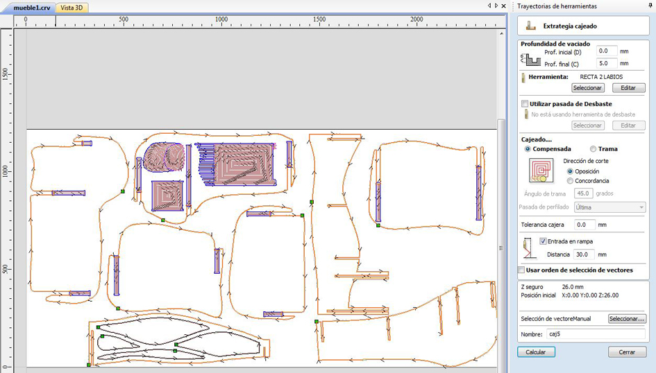
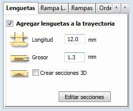
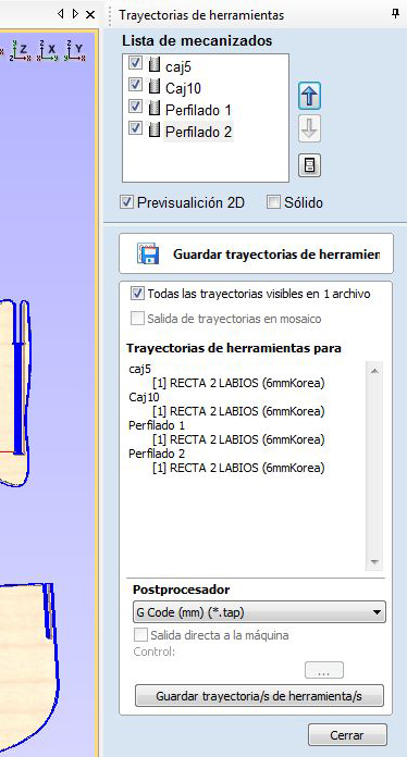
Preparing 5mm cut depth layer (vector selected in pink):
They are shown as a yellow square containing a 'T' in the images above.
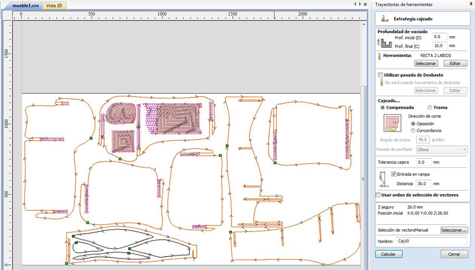
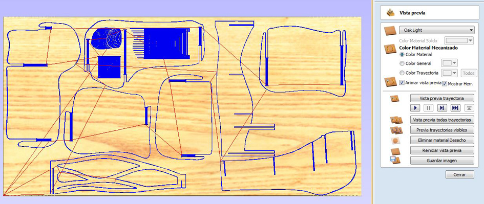
Cut 10mm depth preview:
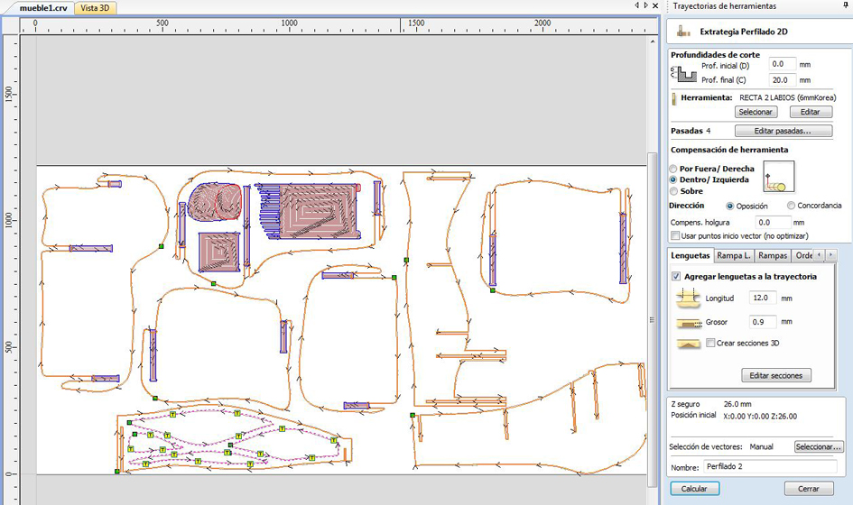
Cut 20mm complete board preview:
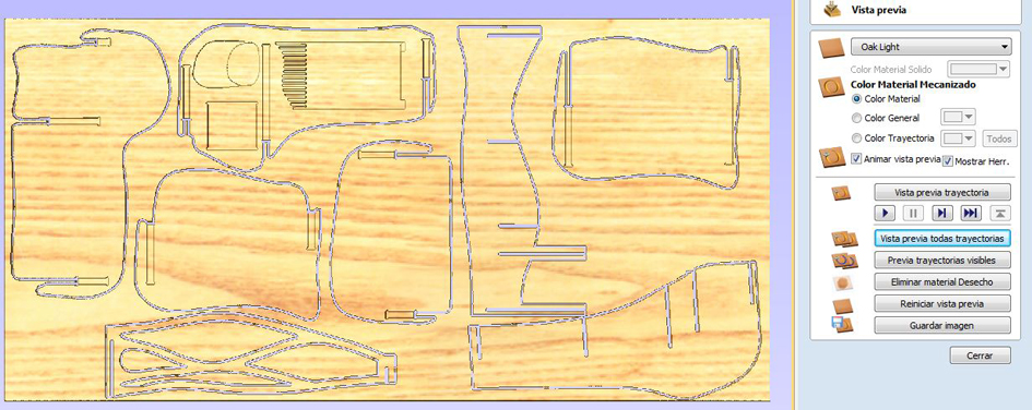
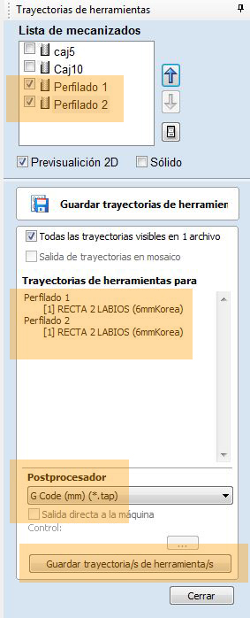
All layer cut preview:
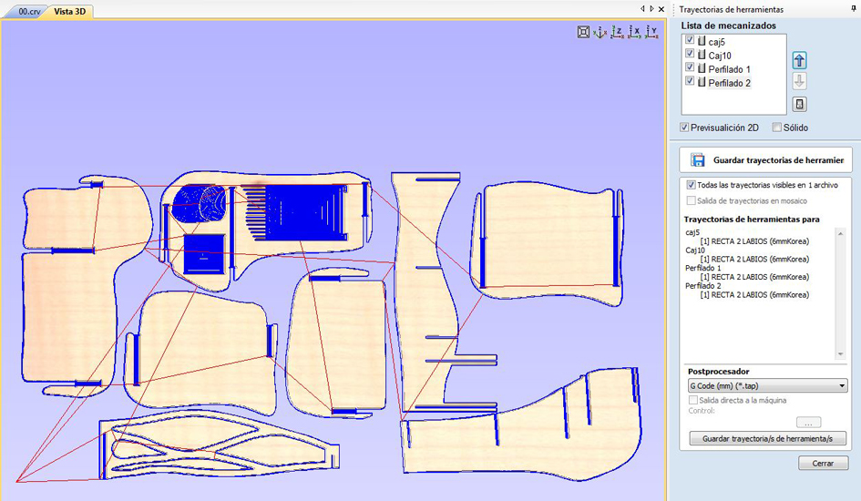
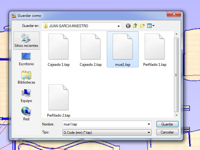
Saving file in .tap extension
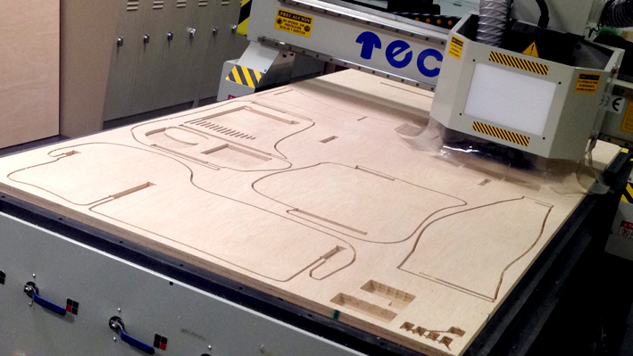
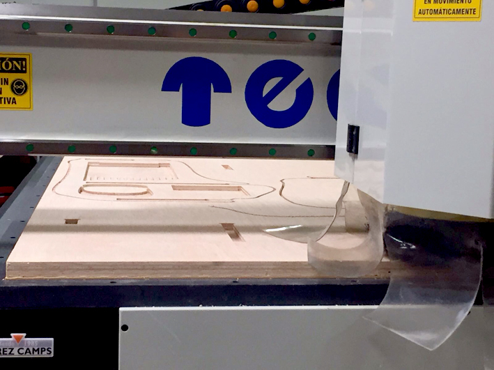
FIRST CUT FINISHED! Problems accounted: as my sacrificial layer was not completely horizontal,
a part of my board was not completely cut. Therefore, with my instructor, we decided to increase the
cut depth from 20mm to 20.7mm, and then flatten the sacrificial layer for the next one who cuts.
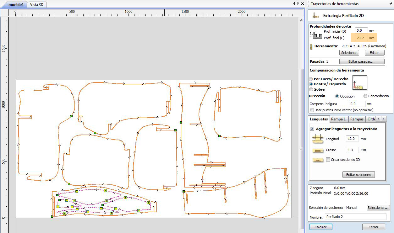
The new parameters that we used were: a complete cut of 20.7mm for the cut depth,
and for the rest of parameters, the same adjustments.
New adjustments (selected vectors in pink):
-Parameters:
-Initial depth: 0.0mm
-Final Depth: 20.7mm
-Way of cutting: conventional, inside cut, outside cut
-File layer selected: corte 20mm segundo (orange and black colour)
Saving file again:
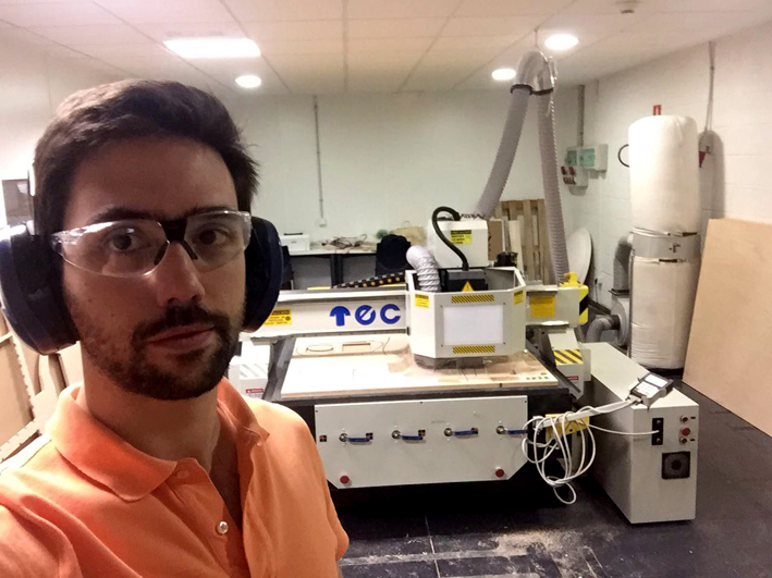
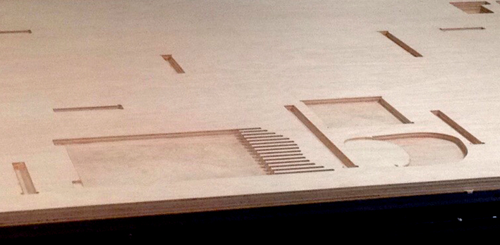
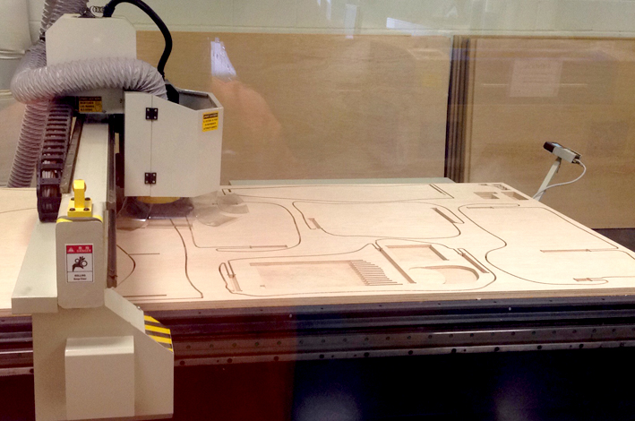
5. Cutting and Building
Building time!
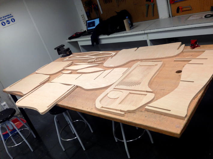
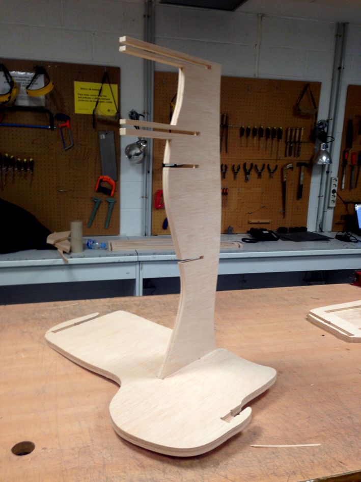
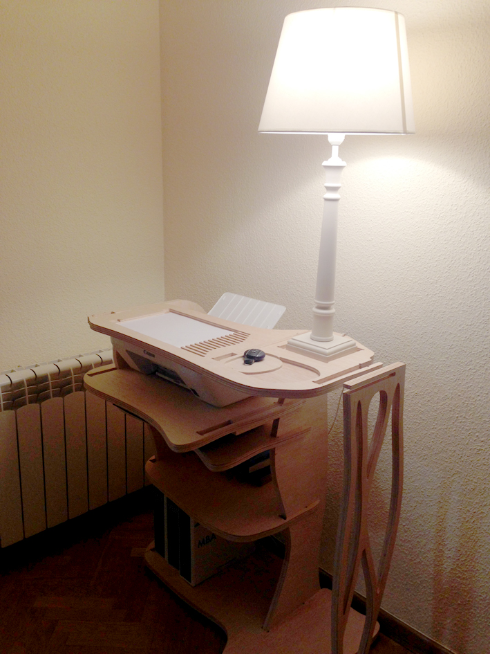
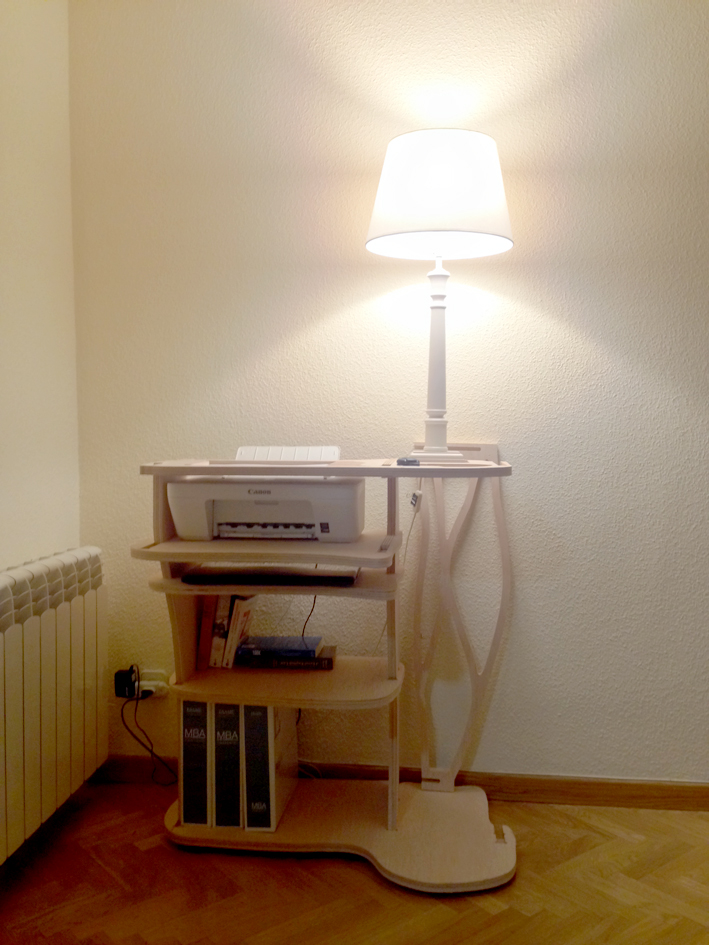
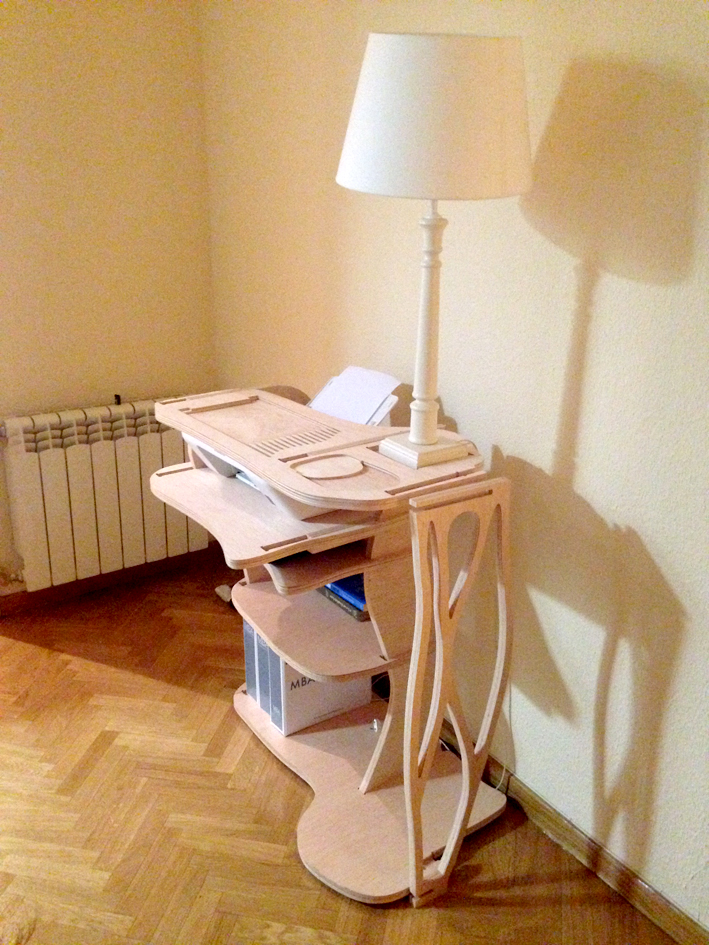
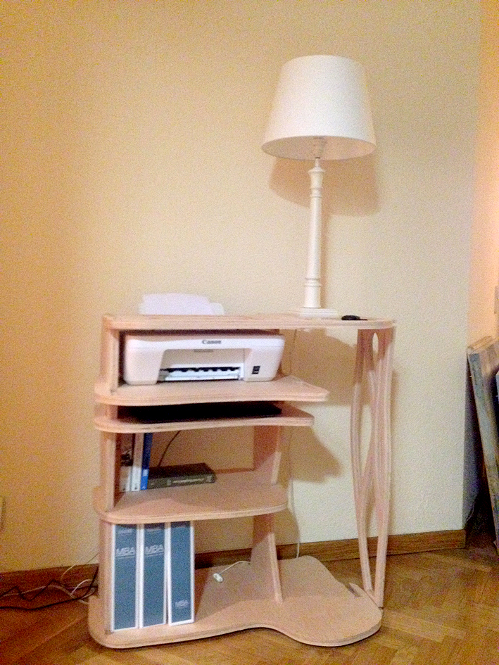
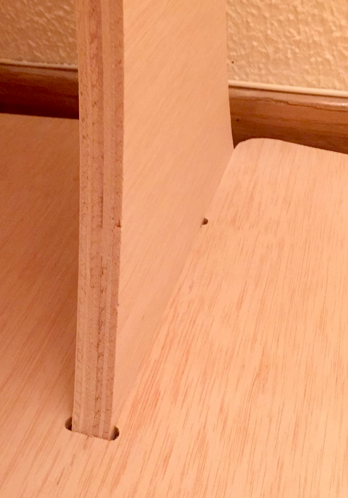
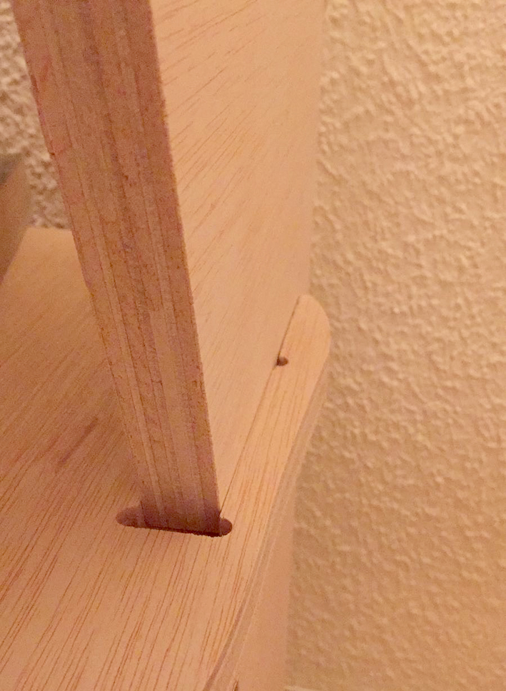
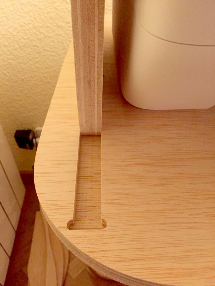
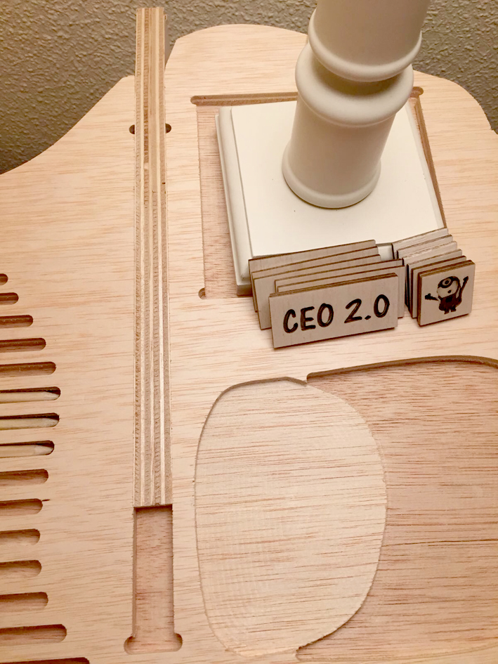
6. Final Result
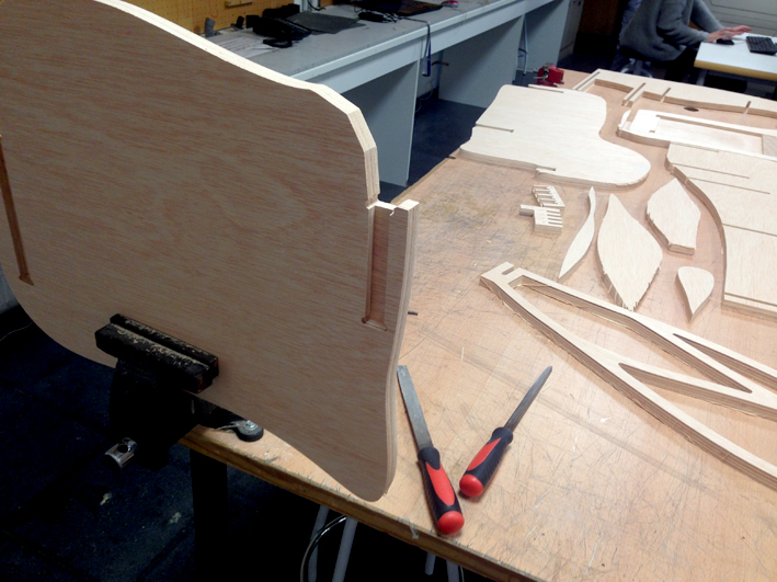
7. Final Result Joints
Nice clean joints:
Uncompleted joints: as I did not have the time to finish it and some of
them were becoming really hard, I decided to build it up to see the final result. I really liked it!
8. Further Analysis
While building my piece of furniture, I had some problems. I completely forgot that the board's
thickness varied between 20.40mm and 20.70mm. The tolerances I used (20.40mm both for height and
width), were not as good as I thought they were.
At first, I had some resistance while building it, but with a hammer and some sweat, it was not a problem.