Juan García-Maestro Gil-Casares

FABLAB MADRID CEU


Final Project - Moving Lamps Prototype v1.0 for Architetural Table


Procedure:
0. Assignment
1. 3d Design: The Idea + Prototype
2. Design + Construction:
2.a - Structure + Components
2.b - Input Devices
2.c - Output Devices
2.d - Networking
2.e - Embedded Programming: The Final Code Used
2.f - Complete Code
2.g - Result
3. Analysis
4. Bill Of Materials
5. Licence And Acknowledgements
6. Download Files
7. Slide
8. Video
9. Reseach Done During The Process

1. 3d Design: The Idea + Prototype


The moving lamp is a lighting tool that makes easier to draw on an architectural table. The workspace is modified by introducing two types of light: atmospheric light and direct light.

Your browser does not support this image

As the person drawing has sometimes their hands full of material and dirty stuff, the lamp will be able to move without actually touching it.

Your browser does not support this image

The idea for creating this is to have:
-Direct Light that can be moved without being touched
-Atmospheric Light placed at the perimeter of the table.
-Change the light's intensity when needed.

Your browser does not support this image


Actual scenario of my table:

Your browser does not support this image Your browser does not support this image

Your browser does not support this image

Prototype


For the Fabacademy2017 I have developed the first prototype. There are two reasons why I have developed a first prototype:
-Following the spiral development, I want to first create a small version of my moving lamp to make sure it works before jumping to the whole sized table.
-The table I want to create has several projects (moving the direct light horizontally, changing light's intensity and having atmospheric light). I decided one of them and build it with the 'Moving Lamp v1.0'.

Your browser does not support this image

As creating the whole table is more complex, I decided to develop the Direct Light device:

Your browser does not support this image Your browser does not support this image

This device moves sideways, on one horizontal axis, to make sure the light can go wherever the user wants.


2. Design + Construction


Your browser does not support this image

Here is the complete design of the prototype. The prototype consists of creating movement with the stepper motor that has been activated by the ultrasonic sensors at the base of the lamp.


Important note: the lamp has not being made as it is another fablab project itself. Once I have more time I want to develop a lamp that can vary its intensity without touching it. This prototype is designed as a guideline to understand this step before continuing with the spiral development.

The software that has been used to develop the prototype has been Rhinoceros, Autocad, Makerbot's software and Lasercutter machine's software.

Structure + Components

Wooden Structure


All what concerns the global structure of my prototype is done with Medium Density Wood (3mm). Its main function is to hold the aluminium rods on its place, plus have the space and the strength to hold all the different parts that the prototype needs (stepper motor attachment, belt's tensor, aluminium rods). The way it is built is by sliding one piece with the other and so on until all pieces are together. No GLUE nor screws are used to build the structure.

In green, we can see on the pictures below which parts of the prototype are done with this material.

Your browser does not support this image Your browser does not support this image

As all the parts have been designed on Rhinoceros, I exported and cleaned up the files with Autocad. On the file, in blue we have one side and in green the other one. Export to dxf file + cut!

Your browser does not support this image

During the process of building up the prototype, here there is a close up to both sides. None of them use no glue nor screws and vessels.

Your browser does not support this image Your browser does not support this image

All the parameters used that have been taken into account for the correct sliding system come from the common website we did for week 3. All the information needed is over there

The method I have followed when cutting with the lasercutter is explained in week 3

Slider


This is one of the most important pieces of the prototype. It has been designed to slide all along the distance of the axis as well as to hold the sonar supports for the input devices redirecting the cables underneath them. Plus, is in charge of holding in place the input board in the middle of both ultrasonic devices and hold on to the belt with the attachment at the bottom side.

At the left hand side column we can see the slider from above and at the right from below.

Your browser does not support this image Your browser does not support this image Your browser does not support this image Your browser does not support this image Export it as .STL file and import into makerbot for the 3d printer to make the rest of the work.

Your browser does not support this image

Taking a look to the left picture, it is easier to understand how the belt is attached to the slider. Then, plasatic bridles are used to hold the belt in place.

Parameters used:

-Layer Height: 0.40mm
-Infill: 20%
-Number of Shells: 2
-Supports: YES
-Raft: NO
-Extruder's Temperature: 200 degrees Celsius.

Having enough space for the input board to be placed in was not a problem. I just measured the distance (the board's width) and created the space on Rhino.

Your browser does not support this image

For the belt, I have designed a way of holding together with this design. Parameters I have used:


-Layer Height: 0.30mm
-Infill: 10%
-Number of Shells: 2
-Supports: YES
-Raft: NO
-Extruder's Temperature: 200 degrees Celsius.

Your browser does not support this image Your browser does not support this image Your browser does not support this image Your browser does not support this image

Your browser does not support this image Your browser does not support this image

At the right, the sonar's supports are already placed on the slider, fitting perfectly with the corresponding male attachment.

Your browser does not support this image

Sonar's Supports


To create a perfect sonar support, it is important to take a look to week's 5 - Group Assignment to understand what parameters I have used.


The way this support work, it that both of them are slided into the male attachement of the slider. Therefore, I needed to know how much plastic expands (for x distance, it normally prints an extra of +0.21 mm. For both parts to slide pefectly, without being loose, I had to make sure I added more space on the sonar's supports and less on the slider.

Some tests done:

Your browser does not support this image Your browser does not support this image Your browser does not support this image

Final Result:

Your browser does not support this image Your browser does not support this image Your browser does not support this image

As it can be seen on the picture above and on the ones while designing the piece, it has 4 holes corresponding to the 4 holes the ultrasonic device has. Unfortunately, I did not have the screws with that diameter to use them. I need to consider having a new way of attaching them to the slider when building my future table.

Parameters used:
-Layer Height: 0.40mm
-Infill: 15%
-Number of Shells: 2
-Support: YES
-Raft: NO
-Extruder Temperature: 200 degrees Celsius

Your browser does not support this image Your browser does not support this image Your browser does not support this image

Belt's Tensor


This is one of the hardest pieces of the prototype. It is based on one of the tensor that are in the Fab Lab Madrid Ceu, and being re-deisgned for my prototype.

Your browser does not support this image Your browser does not support this image Your browser does not support this image

The system consists of three different parts:

-A part attached to the Medium Density Wood Structure, that holds the middle part in two points: one that adjusts the tension and the second one that holds the middle piece in its place.

-A middle part is the one that is able to move and create that tension. A screw is introduced from the structure, through the 'attached' part and then introduced in a screw that holds by the middle piece. This creates the mechanism that allows the system to create that tension.

-On the end, the wheel that makes it possible the belt to move without disturbing the system's tension.

The whole system has been done with 3d printing technology.

Your browser does not support this image Your browser does not support this image Your browser does not support this image

Your browser does not support this image Your browser does not support this image Your browser does not support this image

The black piece is the first part, the white piece is the middle one that has the famous screw inside and at the end in yellow, the wheel.

Your browser does not support this image Your browser does not support this image Your browser does not support this image

The wheel being printed. It is important to have the perimeter limit so the belt does not come out from its place while moving. Several wheels have been done to test this.

The Screw That Makes It Possible To Adjust The Tensor:


This is a test to make sure the vessel entered correctly into the space left for it. This is one of the most important parts as is where the tensor key part to be regulated.

This space is included in the final design, glued with the tensor.

Your browser does not support this image

Stepper Motor's Attachment


The attachment designed for the stepper motor is based on another machine from the fablab. It is just a middle piece that holds together the motor with the structure.

Your browser does not support this image Your browser does not support this image Your browser does not support this image Your browser does not support this image

As it can be seen on the last picture, the tension generated by the tensor has deformed the whole piece. Although it resists really well, one day will need to be rebuilt. Needs to be redesigned for the future table.

The parameters I have used:

Layer Height: 0.30mm
-Infill: 40%
-Number of Shells: 2
-Supports: YES
-Raft: NO
-Extruder's Temperature: 200 degrees Celsius.

Your browser does not support this image Your browser does not support this image

Structure's Stiffness


In order to have a rigid structure to hold together the aluminium rods, additional pieces were needed to stiffen the whole piece.

The longer parts just at the centre of the picture below are designed a longitudinal piece that connects one side with the other to achieve this.

Your browser does not support this image Your browser does not support this image Your browser does not support this image

No glue nor screws were needed to hold everything together. Everything was perfectly designed to match up nicely.

Designing A Belt That Contains The Wires

Your browser does not support this image Your browser does not support this image Your browser does not support this image Your browser does not support this image

At the beginning of the designing process, I had on my mind creating a belt to contain all the wires. This is the initial idea:

Here there are two pieces connected together, being able to move it position and rotating 90 degrees.

In the end, as I was running out of time I could not complete this particular task. On the other hand, it will be completed for the next step of the designing process: the table.

2.b - Input Devices


Ultrasonic devices have been used to record at what distance different obstacles appear on its way. Under certain distance, the board send by serial communication information to the ouput board to activate the stepper motor.

The input device is designed to support 2 sonars (placed in opposite directions), and connected to the board at the bottom. There are 2 1x04 pads where the VCC, GND, ECHO and TRIG pins go (x2).

Must mention that this baords where designed, milled and soldered in 'Week 15 - Networking and Communications'. Please check to understand how I did them.

Your browser does not support this image

The 3 .PNGs used for milling the board.

Your browser does not support this image Your browser does not support this image Your browser does not support this image

As it is a prototype, organising the wires was not solved as I had to learn first how to create all this system and program it. As time was not by my side, unfortunately I could not integrate them as I wished at the beginning.

On the other hand, as I have gone through the whole process of building my device, for the table I will solve certain problems that I had not done in this prototype.

Your browser does not support this image Your browser does not support this image Your browser does not support this image

Top view of the different connections that take place on the board. At the right top side the 1x04 pads that connect the sonar to the boards appear. These wires go up and curl until the go under the slider and through the sonar's support.

I thought this space was enough for the wires to be in, but I did not measure it correctly having most of them hanging out.

2.c - Output Devices


To have a controlled movement, a stepper motor has been used to move the slider from one side to the other. An extra 12 volts supply is needed and a regulator to maintain this voltage.

This board has been designed, milled and soldered in 'Week 15 - Networking and Communications''.

For the stepper motor to move, the board is connected to the input board through serial communication. The board receives a data, it processes it and orders how the motor must move.

The number of steps, speed and how is communicated with the input board is explained in the next chapter.

Your browser does not support this image

These are the 3 .PNGs that have been used to mill the board with mods.

Your browser does not support this image Your browser does not support this image Your browser does not support this image

With already burnt the bootloader, this is how the board is placed on one side of the prototype. I did not have time to create a box that hides and protects it, with all the wires with it.

Your browser does not support this image Your browser does not support this image Your browser does not support this image


2.d - Networking


Once I had the prototype built, I could start testing and calculating different parameters needed for the programming:


- how many steps cover the distance from one side to the other
- how many steps are there in 1 cm.
- at what speed is the slider going to move.
- does it have a continuous movement.

Your browser does not support this image Your browser does not support this image


2.e - Embedded Programming: The Final Code


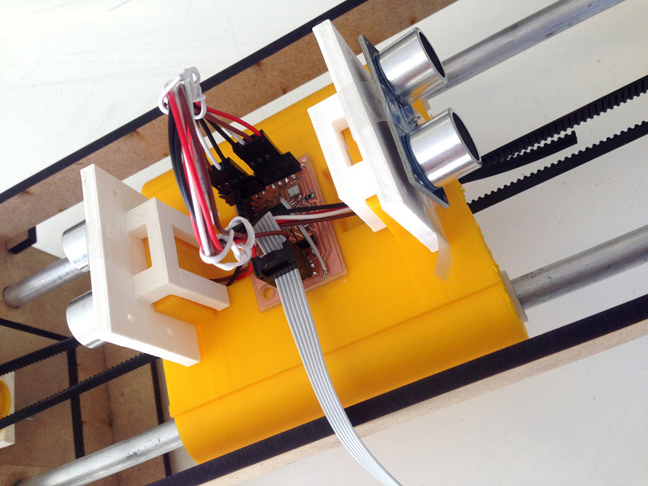
I have two boards that connect with serial communication. During the programming, I had to face up several problems:


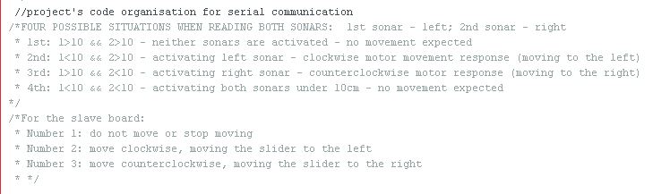
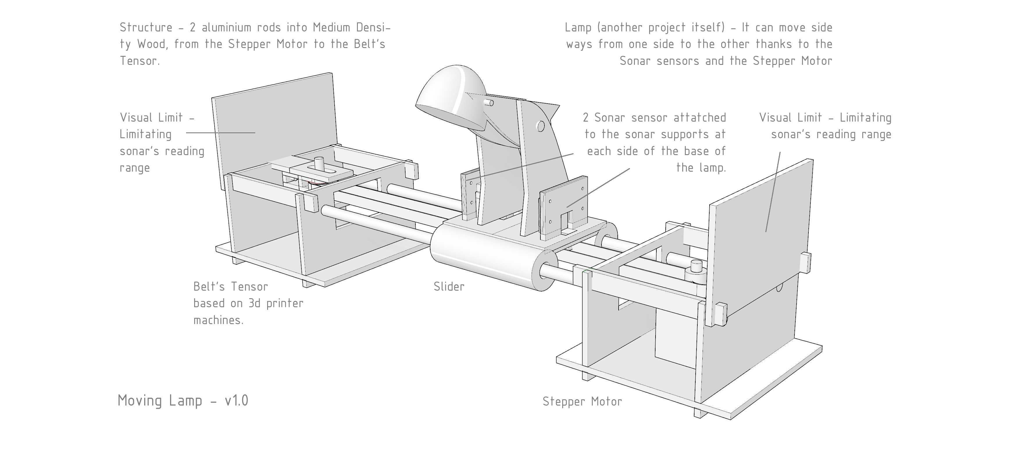
-analyse the four different situations that can take place with the two ultrasonic sensors used.
-make sure the slave board does not saturate from infinite commands sent by the master board.
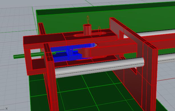
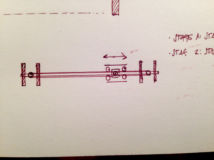
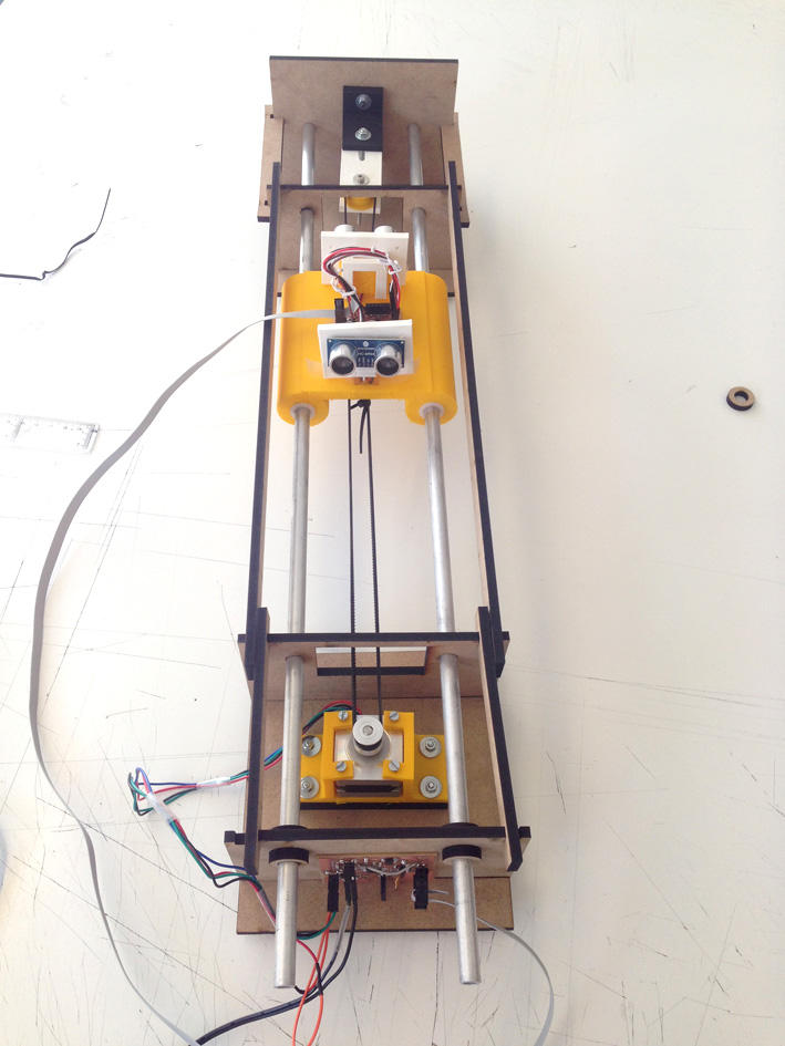
-the slider's position: the system needs to know where exactly the slider is at, what distance has left to both sides.
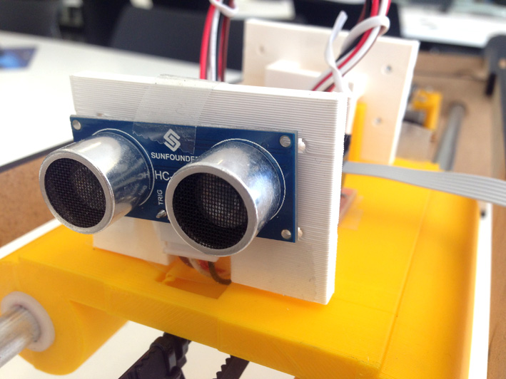
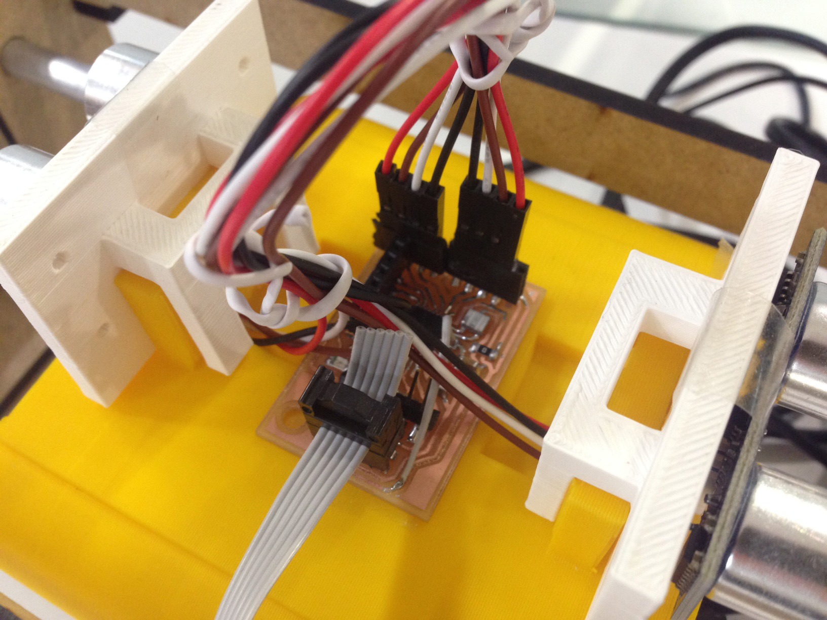
Your browser does not support this image

Input Board:


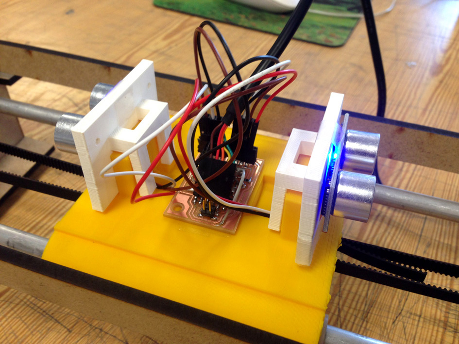
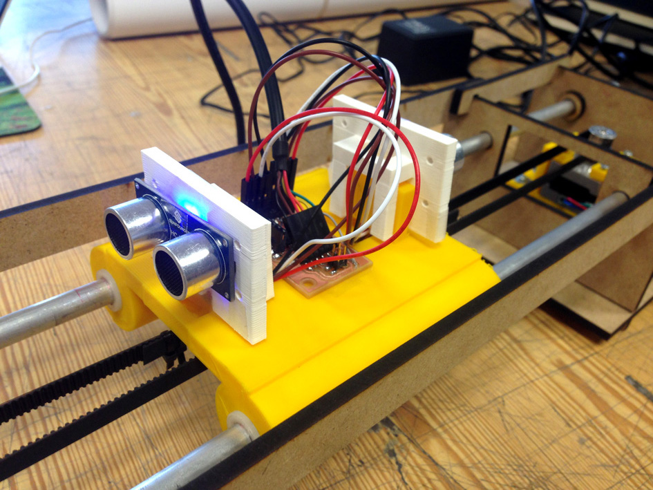
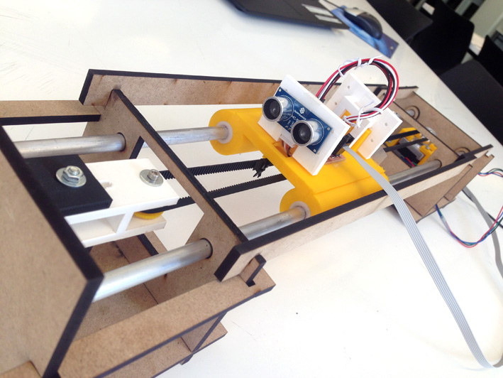
Its responsibility is to analyse if there is an object (my hand) under 10cm. If this is true, then move the slider to one side. Depending on which sonar detects this obstacle, it moves to one side or the other.

The input board is the master board of this system, having the responsibility of:

-send the order to the slave board
-consider all four situations regarding the sonar's readings.
-do not saturate the slave board with orders

Just below, there are two pictures with the most important parts of the input's code. They solve what was written above.

Your browser does not support this image

(code for having an obstacle in sonar1, sending to the slave board number 2)

Sending The Order To The Slave Board

For the board to send the order to that slave board, it uses the command 'mySerial.println(n)'.

Number n can be:

n = 1 - Sends the order to the slave board to not move.
n = 2 - Sends the order to the slave board to move the stepper clockwise, moving the slider to the left.
n = 3 - Sends the order to the slave board to move the stepper counter clockwise, moving the slider to the right.

Analysing The 4 Possible Situations

As you can see on the picture, the first 'if()' is activated depending on the variables 'distance1' and 'distance2'. Each one of this variables have been previously declared assigning them 10. This number 10 refers to the 10cm distance where I will be operating the device. Therefore, if I have my hand under those 10cm, the board will send an order to the salve board. There are four different situations:

-Not reading anything: 'distance1>10' and 'distance2>10', both have measures above 10cm.
-One of the sensors reads an obstacle under those 10cm: 'distance1<10' and 'distance2>10'.
-The other sensor reads an obstacle under those 10cm: 'distance1>10' and 'distance2<10'.
-Both sonars read they have an obstacle under 10 cm: 'distance1<10' and 'distance2<10'.

Depending on each possible situation, the board is going to send one of the number explained before.

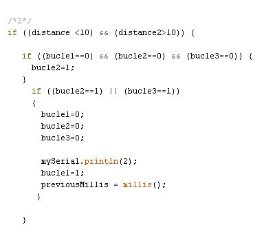
How Not To Saturate The Slave Boards With Too Many Commands

Just below, plus the previous image, you have the code I have used:

Your browser does not support this image

(code when both sonars do not have any obstacles and reassign variables 'bucle1', 'bucle2' and 'bucle3'.)

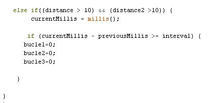
For the board not to send infinite commands, I have used the function 'millis()' to make sure that same command is not repeated all the time. I declare the variable 'interval' (take a look to the code, the image only shows some of it), where I decide how much time it needs to pass so the board can send the same order again.

Initially, 'bucle1', 'bucle2' and 'bucle3' are the variables that make it possible to not send all the time the same command, and the three of them are assigned number 0.

The way it works is very simple: once activated a possible situation, one of the variables changes from 0 to 1. When the loop starts over again, for the same possible situation, there is an initial 'if()' function. This if() function reads: if one of the two other variables are 1, the same command can be sent again, if not, continue with the next part of the code.

Here is the tricky part, I need to wait for the interval to take place so the variables go back to 0 and the same command can be sent again.

Output Board


For the output board (the slave board), receives through serial communication the order. So, depending on the possible situation with the sonars, a number will arrive and activate the stepper motor.

The responsibility of this boards is:
-move the stepper motor so the slider moves to the direction I want to.
-know exactly at what position the slider is so it does not crash to one of the sides.

The orders the board can receive are:
-number 1
-number 2
-number 3

Moving The Stepper Motor

In order to move, I used the command 'myStepper.step(the order. This order can be:

(stopMoving)
(steps)
(-steps)

My strategy is that the motor will move the slider a certain amount of distance each time it receives a number. A non-continuous movement is caused.

My strategy is that the motor will move the slider a certain amount of distance each time it receives a number. A non-continuous movement is caused.

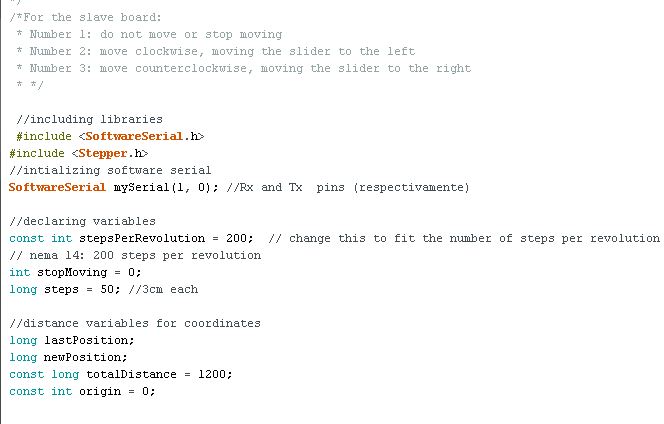
-'stepsPerRevolution': the number of steps the nema-14 stepper motor has are 200.
-'steps': the number of steps I want the stepper motor to do when executing the command: 60.
-'stopMoving': making sure it stops.

As well, there is another command that needs to be declared: setting the stepper motor's speed: 'myStepper.setSpeed(60). In this situation, I decided to have

Your browser does not support this image

Your browser does not support this image

(a part of the output's code, please check the full code either with the file or next chapter).
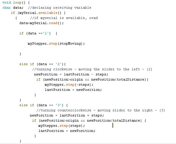
Position


To make sure the slider does not crash onto one side, the board knows exactly where the slider is positioned. To do this, I store its position every time the loop has been executed.

Previously, I have declared these variables:
-origin: constant variable with assigned value 0.
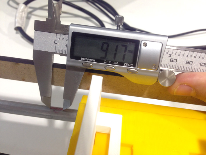
-totalDistance: after testing it, that horizontal axis has a total of 1200 steps.
-lastPosition: it stores the last position the slider was at.
-newPosition: with the number of steps, the slider knows its position.

When number 2 or 3 arrive from the master board, the slave board has the order to move when this condition takes place:
-it calculate what will be the 'newPosition'.
-if the newPosition goes beyond or under the 'totalDistance', it does not execute the command 'myStepper.step(steps)'.

(Check on the images above the code or go to next chapter to see the complete code)
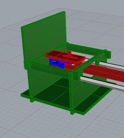
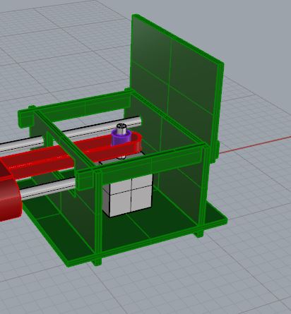
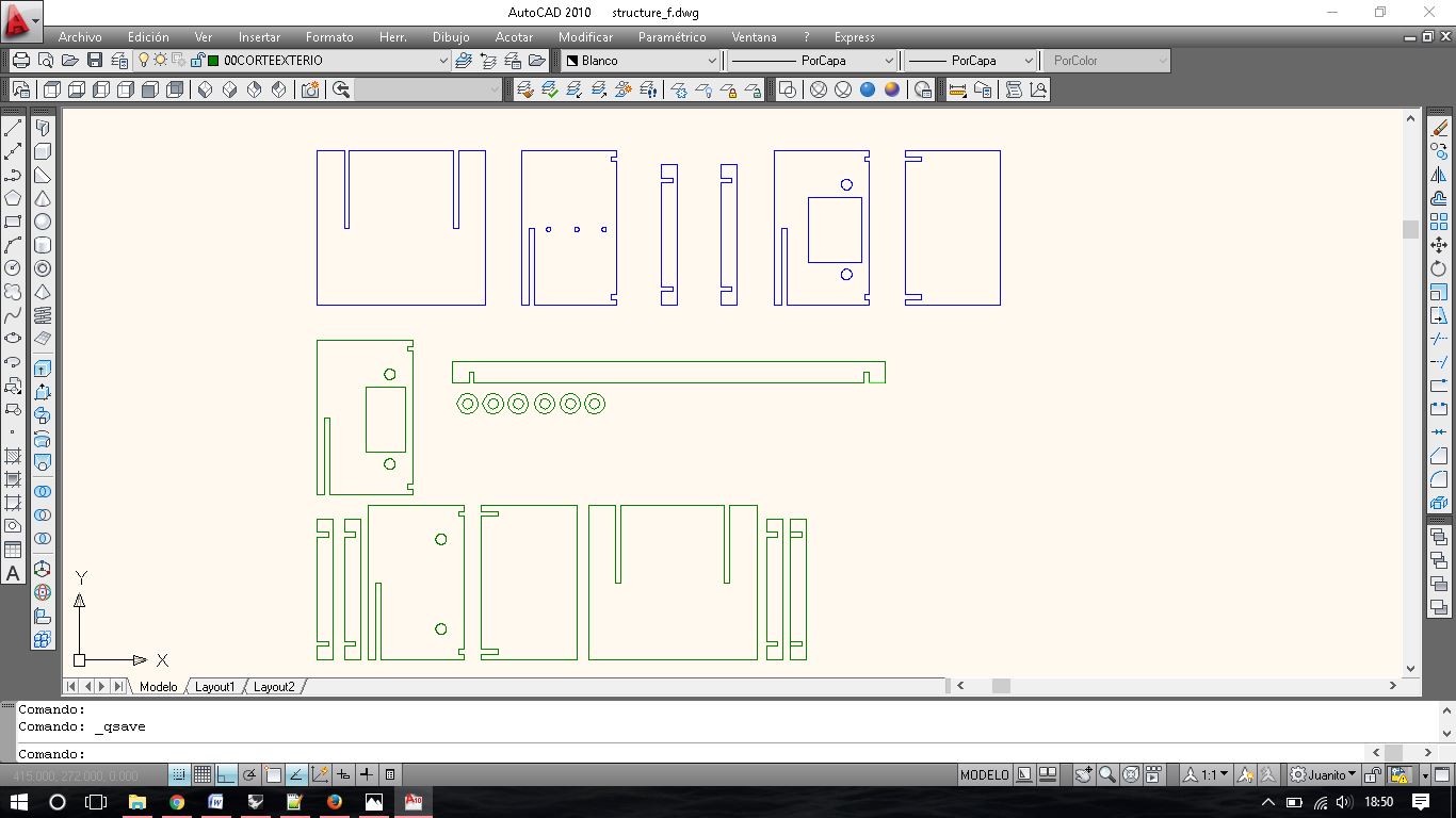
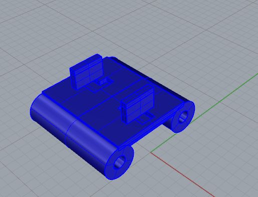
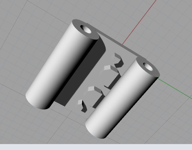
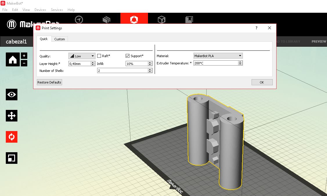
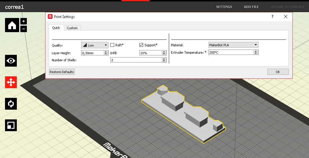
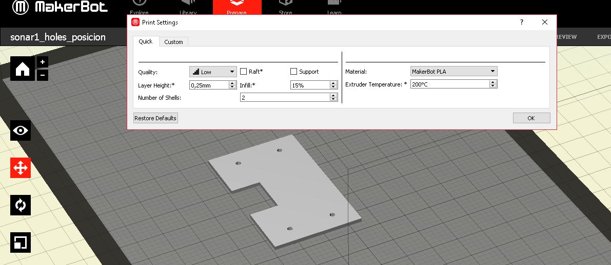
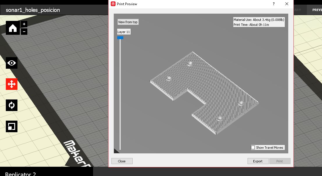
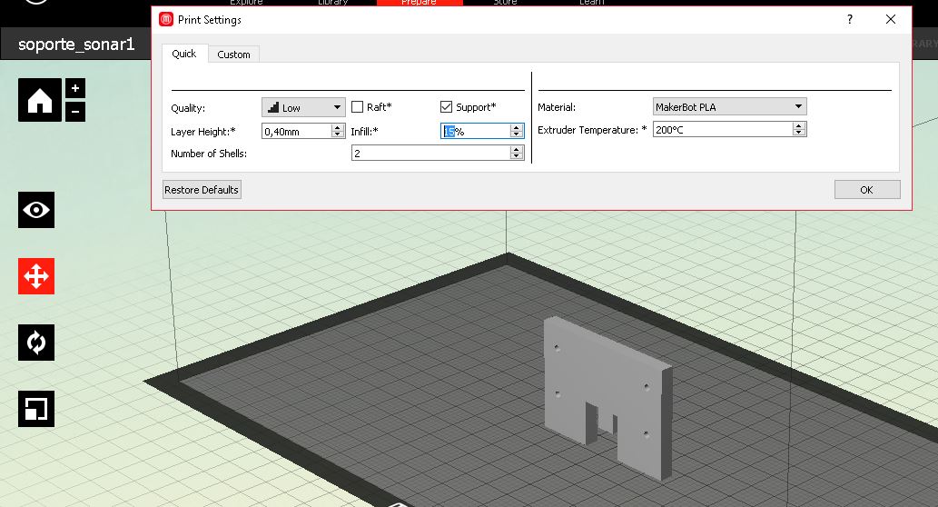
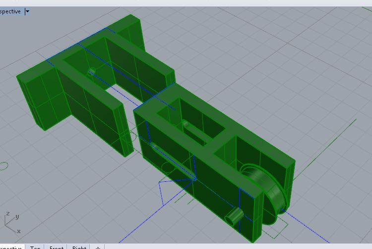
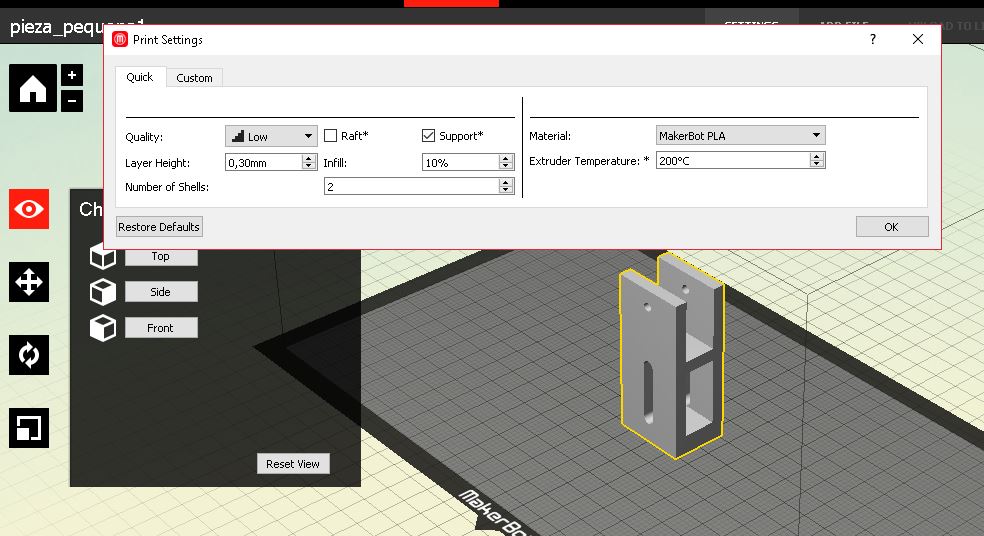
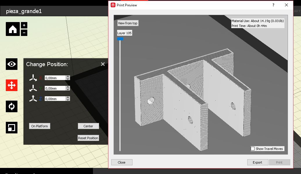
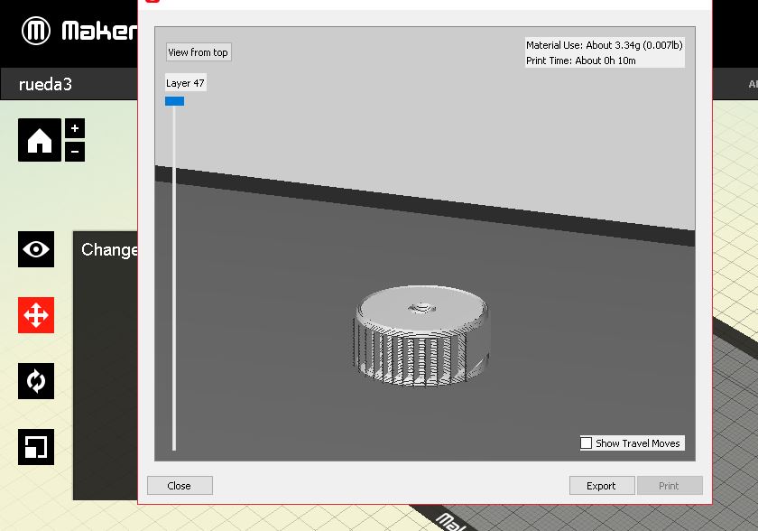
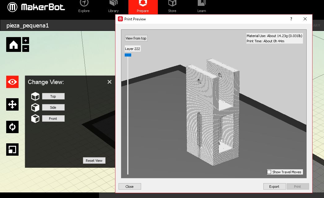
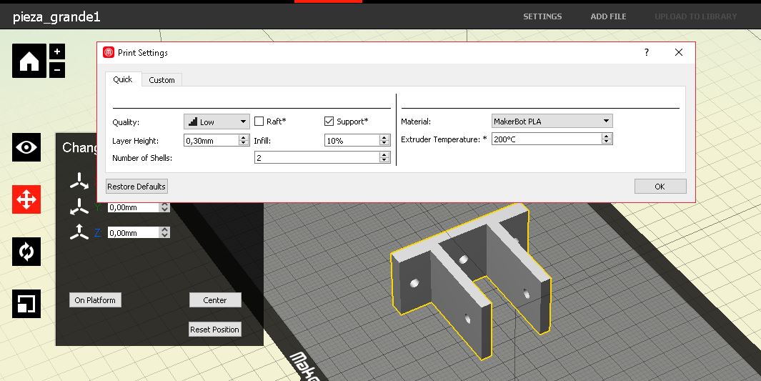
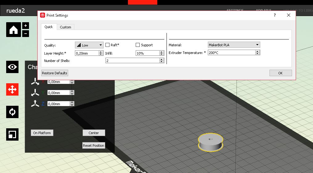
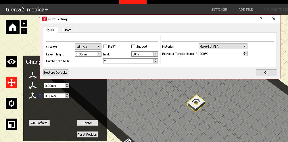
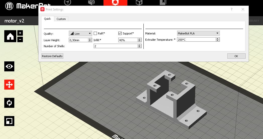
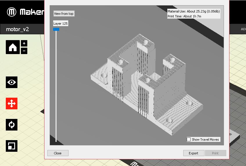
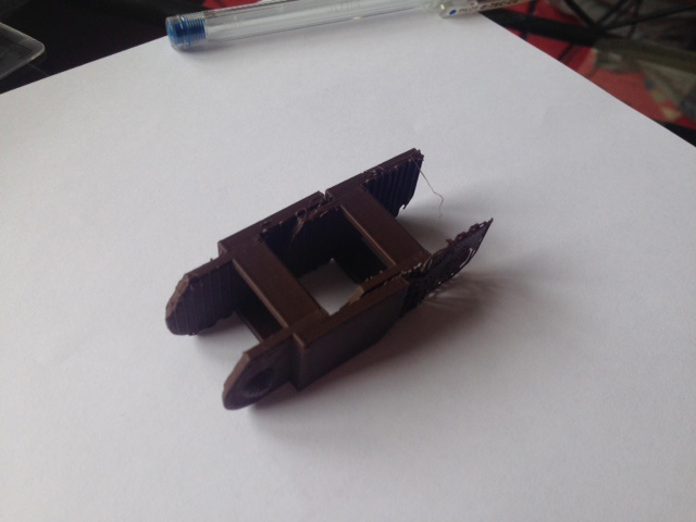
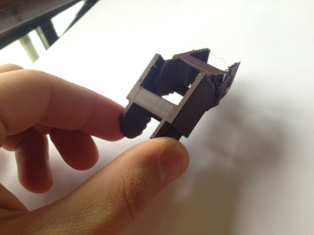
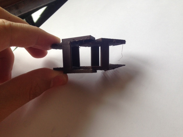
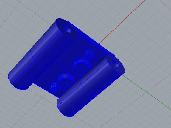


2.f - Complete Code


Input Board's Code

#include <SoftwareSerial.h>
#include <NewPing.h> //including library for ultrasonic sensor
#define TRIGGER_PIN  5 // pin that send a signal
#define ECHO_PIN     6 // pin that receive the signal

#define TRIGGER_PIN2  8 // pin that send a signal
#define ECHO_PIN2     7 // pin that receive the signal
#define MAX_DISTANCE 400 // max distance that the sensor will read

 //initializing both sonars
NewPing sonar(TRIGGER_PIN, ECHO_PIN, MAX_DISTANCE); // establish the new ping telling which are the pins and the max distance
NewPing sonar2(TRIGGER_PIN2, ECHO_PIN2, MAX_DISTANCE); // establish the new ping telling which are the pins and the max distance

//initializing software serial
SoftwareSerial mySerial(0, 1); //Tx and Rx  pins (respectivamente) - cambiado, originalmente (0,1)


//declaring led variable
int redPin = A4; // Red Led Pin
unsigned long rxTime; //define variable sensor 1
unsigned long rxTime2; //define variable sensor 2
float distance; 
float distance2;
int bucle1=0;
int bucle2=0;
int bucle3=0;
unsigned long previousMillis;
unsigned long currentMillis;
const long interval = 1500;


/*float definition: 
 * is a number that has a decimal point. It is used to approximate analog and continuous values
 * because they have greater resolution than integers. Floating numbers can be as large as
 *3.4028235E+38 and as low as -3.40282335E+38.  
 *32-bit storage (4 bytes of information)
 *6-7 digits of precision
 *
 */
 
void setup() {
  // put your setup code here, to run once:

  //beginning baud rate for serial communication
 mySerial.begin(9600);


//pin activation for sonar1
 pinMode(ECHO_PIN,INPUT);
 pinMode(TRIGGER_PIN,OUTPUT); 


 //pin activation for sonar2
 pinMode(ECHO_PIN2, INPUT);
 pinMode(TRIGGER_PIN2, OUTPUT);

 //pin activation for red led
 pinMode(redPin, OUTPUT);   // sets the pins as output

}

void loop() {

  
  // SONAR 1 READ
  // put your main code here, to run repeatedly:
  digitalWrite(TRIGGER_PIN, HIGH);
  delayMicroseconds(10);
  digitalWrite(TRIGGER_PIN, LOW);
  rxTime = pulseIn(ECHO_PIN, HIGH); //read the Receive time
  distance = (float)rxTime * 34 / 2000.0; //Converted into a distance ,cm


  // SONAR 2 READ
  digitalWrite(TRIGGER_PIN2, HIGH);
  delayMicroseconds(10);
  digitalWrite(TRIGGER_PIN2, LOW);
  rxTime2 = pulseIn(ECHO_PIN2, HIGH); //read the Receive time
  distance2 = (float)rxTime2 * 34 / 2000.0; //Converted into a distance ,cm

/*FOUR POSSIBLE SITUATIONS WHEN READING BOTH SONARS:  1st sonar - left; 2nd sonar - right
 * 1st: 1>10 && 2>10 - neither sonars are activated - no movement expected
 * 2nd: 1<10 && 2>10 - activating left sonar - clockwise motor movement response (moving to the left)
 * 3rd: 1>10 && 2<10 - activating right sonar - counterclockwise motor response (moving to the right)
 * 4th: 1<10 && 2<10 - activating both sonars under 10cm - no movement expected
*/

//motor stepper messages
/*For the slave board:
 * Number 1: do not move or stop moving
 * Number 2: move clockwise, moving the slider to the left
 * Number 3: move counterclockwise, moving the slider to the right
 * */


 /*2*/ 
 if ((distance <10) && (distance2>10)) {
    
    if ((bucle1==0) && (bucle2==0) && (bucle3==0)) {
      bucle2=1;
    }
      if ((bucle2==1) || (bucle3==1))
      {
        bucle1=0;
        bucle2=0;
        bucle3=0;
        
        mySerial.println(2);
        bucle1=1; 
        previousMillis = millis();            
       }
    
    }
  
 /*3*/ 
  else if((distance>10) && (distance2<10)) {
     if ((bucle1==0) && (bucle2==0) && (bucle3==0)) {
      bucle3=1;
    }
   
    if ((bucle1==1) || (bucle3==1)){
        bucle2=0;
        bucle1=0;
        bucle3=0;
        
        mySerial.println(3);
        bucle2=1;
        previousMillis=millis();
    }
    
    
  }

/*ambas*/
  else if ((distance <10) && (distance<10)) {
     if ((bucle1==0) && (bucle2==0) && (bucle3==0)) {
      bucle1=1;
    }
    
        if((bucle2==1) || (bucle3==1)) 
        {
          bucle3=0;
          bucle1=0;
          bucle2=0;
        
          mySerial.println(1);
          bucle3=1;
          previousMillis=millis();
          }
    
  } 
    
   else if((distance > 10) && (distance2 >10)) {
        currentMillis = millis();
  
       if (currentMillis - previousMillis >= interval) {
      bucle1=0;
      bucle2=0;
      bucle3=0;
      
    }
 
}
}


Output Board's Code


/*
 Stepper Motor Control - one revolution
 This program drives a unipolar or bipolar stepper motor.
 The motor is attached to digital pins 8 - 11 of the Arduino.
 The motor should revolve one revolution in one direction, then
 one revolution in the other direction.
 Created 11 Mar. 2007
 Modified 30 Nov. 2009
 by Tom Igoe
 June 5th Modified By Juan GM
 */
 //project's code organisation for serial communication
/*FOUR POSSIBLE SITUATIONS WHEN READING BOTH SONARS:  1st sonar - left; 2nd sonar - right
 * 1st: 1>10 && 2>10 - neither sonars are activated - no movement expected
 * 2nd: 1<10 && 2>10 - activating left sonar - clockwise motor movement response (moving to the left)
 * 3rd: 1>10 && 2<10 - activating right sonar - counterclockwise motor response (moving to the right)
 * 4th: 1<10 && 2<10 - activating both sonars under 10cm - no movement expected
*/
/*For the slave board:
 * Number 1: do not move or stop moving
 * Number 2: move clockwise, moving the slider to the left
 * Number 3: move counterclockwise, moving the slider to the right
 * */

 //including libraries
 #include <SoftwareSerial.h>
#include <Stepper.h>
//intializing software serial
SoftwareSerial mySerial(1, 0); //Rx and Tx  pins (respectivamente)

//declaring variables
const int stepsPerRevolution = 200;  // change this to fit the number of steps per revolution
// nema 14: 200 steps per revolution
int stopMoving = 0; 
long steps = 50; //3cm each

//distance variables for coordinates
long lastPosition;
long newPosition;
const long totalDistance = 1200;
const int origin = 0;


//declaring led variable
int redPin = A4; // Red Led Pin

// initialize the stepper library on pins 5 through 8:
Stepper myStepper(stepsPerRevolution, 5, 6, 7, 8);
/*Function Stepper - 4 ways of doing it:
 * Stepper (steps, pin1, pin2): 
 *      steps: number of steps in ONE REVOLUTION.
 * 
 * Stepper (steps, pin1, pin2, pin3, pin4)
 * 
 * setSpeed (rpm): this function does not make the motor turn, it just sets the speed 
 * at which it will turn when called a step
 * 
 * step(steps)
 * 
 */


void setup() {
  
  // set the speed at 60 rpm:
  myStepper.setSpeed(60);
  
  // initialize the serial port:
  mySerial.begin(9600);

  pinMode(redPin, OUTPUT);
  digitalWrite(redPin, LOW);

  lastPosition = 0;
}


void loop() {
char data;  //declaring receiving variable
    if (mySerial.available() )   
      {      //if myserial is available, read
        data=mySerial.read();

        if (data =='1')  {
            /*digitalWrite(redPin, HIGH);
              delay(2000);
              digitalWrite(redPin, LOW);
              delay(2000);*/
            myStepper.step(stopMoving);  
             /* analogWrite(redPin, LOW);//rhythm to tell the one doing it to stop it.
              delay(500);
              
              analogWrite(redPin, HIGH);
              delay(500);*/
        }

        else if (data == '2'){
              /*turning clockwise - moving the slider to the left - (2)
               */   
               newPosition = lastPosition - steps;
                if (newPosition>origin && newPositionorigin && newPosition


2.g - Result


The Machine:

Your browser does not support this image

Your browser does not support this image

Your browser does not support this image Your browser does not support this image


Your browser does not support this image Your browser does not support this image

Your browser does not support this image Your browser does not support this image

Your browser does not support this image Your browser does not support this image

Your browser does not support this image Your browser does not support this image

Your browser does not support this image Your browser does not support this image


Video:


More Videos


3. Analysis


What Does It Do?


The 'Moving Lamp v1.0' moves to the direction the user tells by activating one of the sonars at the base of the lamp. It can move sideways all the way from one side to other without 'crashing' into the structure.

The input is programmed to read an obstacle, and if they are 10 cm or less from the sensor (the distance can be modified), it sends through serial communication a command. The output board receives and starts the slider's motion according to what it has received.

Video


Who's Done What Beforehand?


This questions is answered on the


What Did You Design?


With the exception of the stepper motor itself, the lamp used, 12 volt supply and the belt used; the rest of the prototype is designed and built by myself.

All the different parts are:
-structure made out of medium density wood that hold the aluminium rods for it to slide.
-structure stiffness .
-the slider made out of pla.
-sonar supports made out of pla.
-electronic system: input board for 2 sonar to read at the same time and an output board connected to the first one through serial communication.
-design of the belt's attachment to slider.
-design of the belt's tensor.


What Materials And Components Were Used?


All the materials used are described in the BOM

Where Did They Come From?


All the materials used come from the fablab inventory:
-PLA for 3d Printer
-Medium Density Wood - 3mm
-Aluminium Rods (Recycling the ones that remained from the machine and were not going to be used).
-Stepper Motor
-Ultrasonic Sensor
-Electronic components
-Other material such as screws, vessels, etc.


How Much Did They Cost?


What Parts And Systems Were Made?


All these parts have been made in the fablab:
-Medium Density Wood Structure
-Slider PLA
-Sonar Supports PLA
-Belt's Tensor - PLA + screws + vessels
-Input Device Board
-Output Device Board
-Serial Communication Cable


What Processes Were Used?


-Lasercutting
3d Printing

What Questions Were Answered?


····


Is the slider going to move in a continuous movement?

YES. At the beginning I had some problems with the rods. It had some rough parts that did not let the slider to move smoothly.

After sanding them + some oil, I had this continuous movement.

····


Are the sonars prepared to react to errors like both having obstacles at the same time?

What I have done is when the sonars read an obstacle under 10 cm, send an order to the ouput board for the stepper motor to move. For each sonar, there are 2 possible situation, or either the obstacle is under 10 cm o over it. As we have 2 sonars, there are 4 possible situations:

Sonar 1 < 10cm; Sonar 2 < 10cm: do not send any command to output board
----
Sonar 1 > 10 cm; Sonar 2 > 10 cm: as well do not send any command to output board
----
Sonar 1 > 10 cm; Sonar 2 < 10 cm: send command 1 to output board to move the slider in one direction.
----
Sonar 1 < 10 cm; Sonar 2 > 10 cm: send command 2 to output board to move the slider in the opposite direction.

As all possible situations are included in the programming, no errors take place when operating the whole system .

····


How Was It Evaluated?

It works. I have successfully created a moving lamp in its simplest form. Now the new challenge is to go to the bigger scale and actually make for the architectural table with the other projects for it.

····


What Are The Implications?

Having successfully done this first prototype, it encourages me to continue with the process of making the other projects to complete the Architectural Table Lightning Device. This will improve my drawing environment making it easier for me to stay focused without having problems with my own shadow.

In the next version of my moving lamp, the design will be carefully done so especially no wires get tangling in the middle as it happens in this prototype. The idea was to be as functional as possible (as I am new to electronics and programming) and later on have a better design.


4. Bill Of Materials


In total, the prototype costs 90 euros.

Your browser does not support this image


5. Licence And Acknowledgements


As my Final Project is a non-profitable a does not have a commercial purpose, the best licence is to have a Creative Commons Non-Commercial Licence so anyone can have access to it and learn all the lessons I have done while making it, crediting for my creation.

Your browser does not support this image

6. Download Files


7. Slide


Your browser does not support this image


8. Video


Video


2. Design + Construction

3. Searching For The Ideal Slider Mechanism


As my table has a really long distance, I need make sure I can make a rail or a slide as long as the table is. I have been researching and thinking about different ways of doing it. I thought of two possible solutions, being the latter the best one.

1st mechanism: it can become unstable easily unless a perfect execution during the building process is done.

Your browser does not support this image Your browser does not support this image

2nd possible mechanism: for long distances, having 12 wheels keeping the slider on its place:

Your browser does not support this image Your browser does not support this image

3rd possible mechanism:

Here now I have something to really think about

Your browser does not support this image

After talking with my instructor and how I am going to do it, he told that there were extra aluminium rods from week 9 and week 11 (the machine). He suggested me to instead of creating the whole axis from 0, to use them and create a new slider that adapts to it.

4th possible mechanism:

Your browser does not support this image

I decided to continue with this last mechanism. As I do not have that much time, it can save me a lot of time.


MENU