Week 5 - Group Assignment - Tests about 3D Printers
Group Members
Daniel Amigo
Álvaro Fernández-La Roja
Juan García-Maestro
Javier Burón
Pilu Caballero
3D Printers References Learned
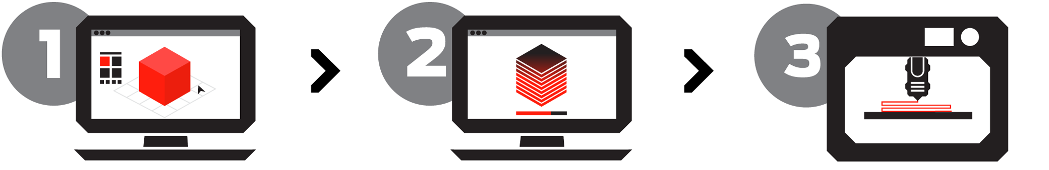
3D printing, also known as additive manufacturing (AM), refers to processes used to create a three-dimensional object in which layers of material are formed under computer control to create an object.Objects can be of almost any shape or geometry and are produced using digital model data from a 3D model or another electronic data source such as an Additive Manufacturing File (AMF) file.
3D printable models may be created with a computer-aided design (CAD) package, via a 3D scanner, or by a plain digital camera and photogrammetry software. 3D printed models created with CAD result in reduced errors and can be corrected before printing, allowing verification in the design of the object before it is printed.
The manual modeling process of preparing geometric data for 3D computer graphics is similar to plastic arts such as sculpting. 3D scanning is a process of collecting digital data on the shape and appearance of a real object, creating a digital model based on it.
Before printing a 3D model from an STL file, it must first be examined for errors. Most CAD applications produce errors in output STL files:holes, faces normals, self-intersections, noise shells or manifold errors.A step in the STL generation known as "repair" fixes such problems in the original model.Generally STLs that have been produced from a model obtained through 3D scanning often have more of these errors.This is due to how 3D scanning works-as it is often by point to point acquisition, reconstruction will include errors in most cases.
Once completed, the STL file needs to be processed by a piece of software called a "slicer," which converts the model into a series of thin layers and produces a G-code file containing instructions tailored to a specific type of 3D printer (FDM printers).This G-code file can then be printed with 3D printing client software (which loads the G-code, and uses it to instruct the 3D printer during the 3D printing process or use a memory card for input in the machine.
Our Printer : The Makerbot Replicator 2
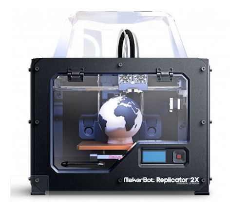
-Build volume: 285 x 153 x 155 mm
-Nozzle Diameter: 0.4 mm
-File types: X3G
-Software bundle: MakerBot desktop
-Filament: PLA of 1.75 mm
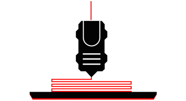
FDM or Fused Deposition Modeling
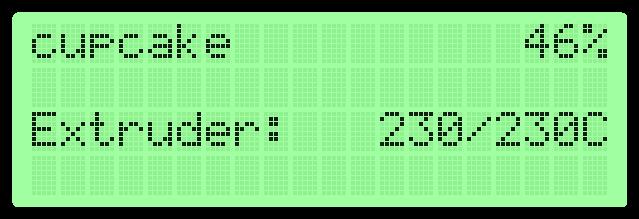
MakerBot's 3D Printers rely on a technology called Fused Deposition Modeling or FDM. It uses an extruder, which acts similar to a hot glue gun. Plastic filament is fed in through the top, is melted at 215℃, and finally is “extruded” out of a small nozzle into the layers that build a 3D print.
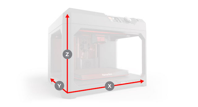
MakerBot 3D Printers know where to move using a three dimensional cartesian coordinate system which defines every point of a 3D model with a unique position along the X, Y, and Z axes. The coordinates are fed to the printer from MakerBot Print and MakerBot Mobile.
Rafts and Supports
Prints with Overhangs
An overhang is when a layer extends outward, potentially unsupported, over the previous layer. If your models have overhangs greater than 68 degrees (measured from the vertical axis) for PLA Printers, then you will need to print with support material.
What are Rafts & Supports? Supports are printed scaffolding for overhangs. You can turn on supports in MakerBot Print. A Raft helps with adhesion to the build plate by laying down an even flat foundation. Rafts are turned on by default in MakerBot Print.
Completed Print Both rafts and supports are physically removed after the print is finished. Once rafts and supports are removed, the model is complete!
Infill Percentage
Number of Shells
Shells are the outer layers that make up the surface of your prints. Adding more shells does not affect its external dimensions, but can make your object stronger.
Layer Height and Print Resolution
Layer Height, also known as Print Resolution, changes the surface quality of a 3D print. Low resolution means the layers are thicker, objects print faster, and the surface quality is rougher. High resolution means the layers are thinner, objects print slower, and the surface is smoother. We suggest printing at our standard print quality.
LCD Screen Menus
Build from SD
To print an .x3g file from an SD card, just select Build from SD using the M button and use the up and down arrows to choose from the list of files you have on your SD card. Press M to start the print. Select Exit Menu to return to the main screen.
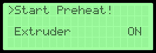
Preheat
Utilities
The Utilities menu contains controls for your printer and scripts for processes like loading filament and leveling the build plate.

Monitor Mode
Level Build Plate
You can use Level Build Plate to walk you through the plate leveling process. This script moves the extruder to different points on the plate, allowing you to adjust the plate height at each point. You can always stop the script in the middle by pressing the left arrow and selecting “Yes” when your Replicator 2 asks you if you want to quit this process.
Home Axes moves your build platform and extruder to their Home positions. If you want to move them anywhere else, you can use Jog Mode.
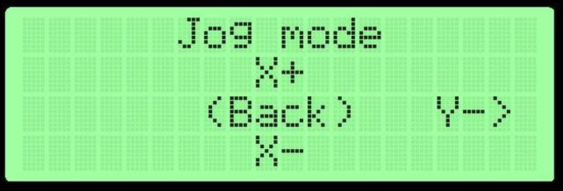
Jog Mode
In Jog Mode, use the left and right arrows to choose an axis and the up and down arrows to move your extruder or build platform along that axis. Jogging the Z axis will move your platform up and down, and jogging the X and Y axes will move your extruder right and left and backwards and forwards, respectively.
Run Startup Script will take you to the script that the Replicator 2 runs when you turn it on for the first time. It will walk you through leveling your build plate, loading filament into both extruders, and printing from the SD card. You can exit the startup script by hitting the left arrow, but not until the leveling sequence has begun.
Use the M to select Blink LEDs, and the LEDs in the Replicator 2 will start blinking. The menu item will change to Stop Blinking! and you can press the M again to turn the blinking off.

How to Change Filament
The easiest way to change your filament on your MakerBot Replicator 2 is to use the LCD panel :
On the LCD panel, select Utilities > Change Filament > Unload.
Wait for the extruder to heat to the set temperature, push down on the extruder arm and continue to hold it down as you gently pull the filament out of the extruder. Then release the extruder arm. If the extruder on your MakerBot Replicator 2 does not have an extruder arm, just pull the filament free of the extruder.
Remove the old spool and replace it with the new spool, feed the PLA Filament through the filament guide tube. Go to the LCD panel and select Utilities > Change Filament > Load.
The MakerBot Replicator 2 will start to heat your extruder. When the extruder is heated, the LCD panel will prompt you to load the filament into the extruder. Click through the message until your MakerBot Replicator 2 asks you to press the M when you see plastic extruding.If your extruder has a lever arm at the side, push it down and hold it in place. If you have an extruder without an arm at the side, continue to the next step.
Insert the free end of the filament into the hole in the top of the extruder. Push the filament down until you feel the motor pulling it in. Wait until you see plastic start to emerge from the extruder nozzle. If your extruder has an extruder arm, release it. Watch to make sure plastic is still extruding from the nozzle. Then press the M button to stop extrusion.
- Note: If you're changing colors, you'll need to run the extruder for a few moments to clear out the old color before stopping extrusion. If you're changing materials, it can take even longer.
- make sure that all the old material is extruded before you start a new print. Push the guide tube back into the opening on the top of the extruder.
You can change filament during the print process to create a print with layered colors. Press the left arrow button to get to the Active Build menu, then select Change Filament. The extruder will move away from your print. Select Unload, then replace the spool and filament as you did in the steps above. After you change the filament, select the left arrow button to return to the Active Build menu. Select the entry for Resume Print.
Learning about Levelling the Build Plate
On the LCD panel, select Utilities > Level Build Plate. The LCD screen will guide you through the assisted leveling routine. At each stage, you will be directed to turn one of the leveling knobs on the underside of the build platform.
See the following video if you need additional help:
Learning about the extruder for Solve Problems : MAINTENANCE
Disassembling an Extruder
Occasionally you may need to take the extruder apart for troubleshooting purposes. This is a simple process that will require no tools other than the 2.5 mm hex wrench you received with your MakerBot Replicator 2.
1. Unload the Filament from the extruder. To run the script for unloading filament, go to the LCD panel and select Utilities > Filament Options, then select Unload.
2. Once any filament is unloaded, switch off the power on the MakerBot Replicator 2 and unplug the power supply. Pull on the connector to release it from the power input port.
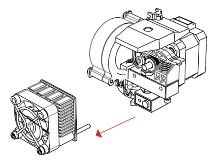
3. Unscrew the two bolts at the lower corners of the fan guard using the 2.5 mm hex wrench included with your MakerBot Replicator 2. As one piece, remove the fan guard, the fan, the heat sink, and spacers. Keep these pieces together and set them aside.
4. Unclip the motor wire.
5. Pull the motor assembly out.
The extruder is now broken down into its main assemblies.
It may help to watch the "cleaning the drive gear" part of this video, beginning at 1:27:
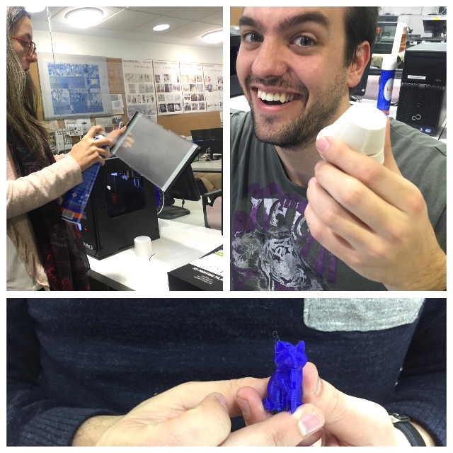
GROUP PRACTICES
First we made was organizer the task for made, as Daniel, Pilar and Javier have some experiences with 3D Printers, we decided that Alvaro and Juan must to learn some things and they began with first testers.
Our goals on these test were:
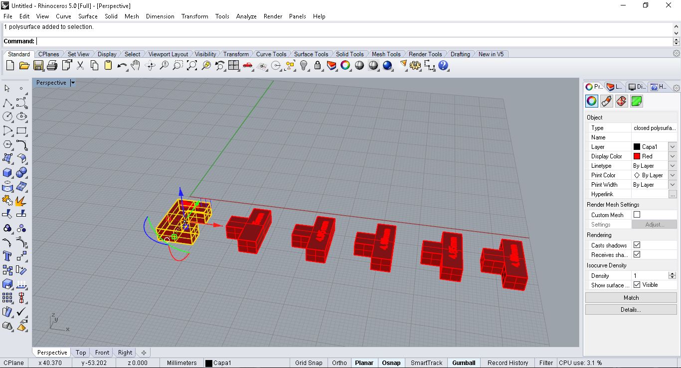
Test 01: Fidelity of the pieces with respect to the virtual model
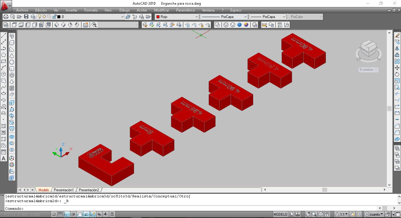
The goals within this test are to see the differences between a virtual object Vs the printed object plus the adjustments needed to build a male-female system.
The male-female systems consists of creating two different objects that join together, having one protrusion in one of them (male) that inserts into the other (female).
Therefore, we have designed two different pieces where the male varies its width in steps of 0.05mm (protrusion's widths tested:
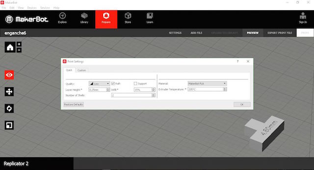
Rhinocerose Design Software
Material : PLA Filament
Layer : 0,28 mm
Temperature : 205º
Speed: 80
Support: NO
Time spent : 3 minutes x 10 Units
a = protrusion's virtual width
ar= protrusion's printed width
h=printed height (all parts have a 4mm height.
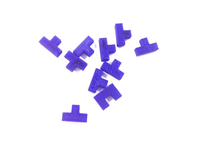
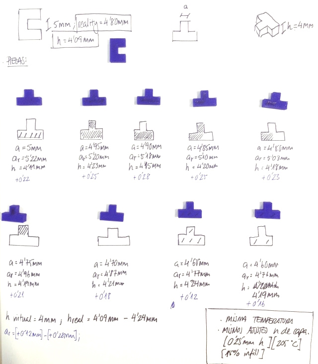
CONCLUSIONS :
1. On the vertical axis (Z) having 0.25mm per layer, the machine prints and extra +0.18mm on average (for a height of 4mm, we should expect a height of 4.18mm).
2. On the other hand, trying out the male-female system, the results were that for a virtual 4.85mm male's protrusion fitted correctly in a virtual 5mm width.
3. In other words, for a printed 4.85mm protrusion (male), it fitted correctly in a 4.80mm gap (female), considering that the joint does not move, but still has the ability to detach without much force.
4.What we learnt is that, while designing a joint, we should consider increasing the female's width (gap) and reducing the male's width of its protrusion in order to work with a virtual difference of 0.25mm, being in reality 0.05mm.
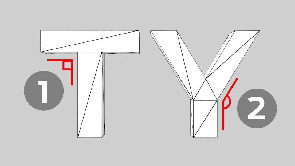
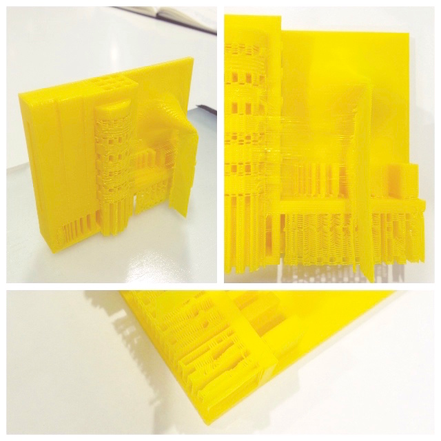
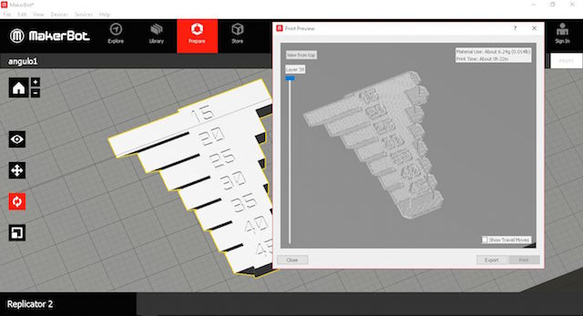
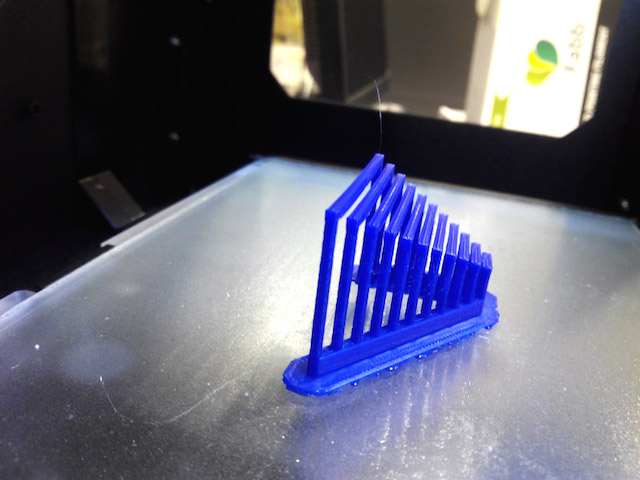
TEST 2: Know the angle from which the stairs are formed and the piece ceases to be flat and minimum wall thickness.
The main goal of this test was to see until what angle our Makerbot Replicator 2 was able to print each layer without having problems. Instead of designing our own file, we went to thingiverse.com and chose an specific object that has been designed to do so.
1. We used first the object that Neil commented at the Week Lectures(3D printer tolerance test). To check differents parameters:
Reference Design
-3D printer tolerance testWe try to print this piece several times. The first time we print in the wrong position :
Problems accounted:
We Print the piece without bridge, so we decided to try again.
2nd ATTEND
The second time we print in the correct position but we had a problems with the raft. We used this parameters :
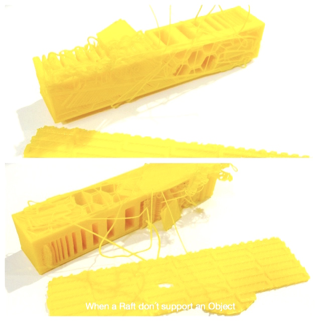
CONCLUSIONS
As shown on the picture where the object is faced down, although under an angle of 15 degrees the machine has been able to print successfully every layer, the performance is considerably lower.
Therefore, if you want to print something with a nice finished layer, you should not go under 20 degrees on your design.
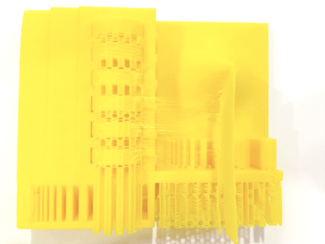
3rd ATTEND
For the last Attend Javier printed the test design with another filament in the wrong position too, but the result about the filament was fantastic and we decided to show it :
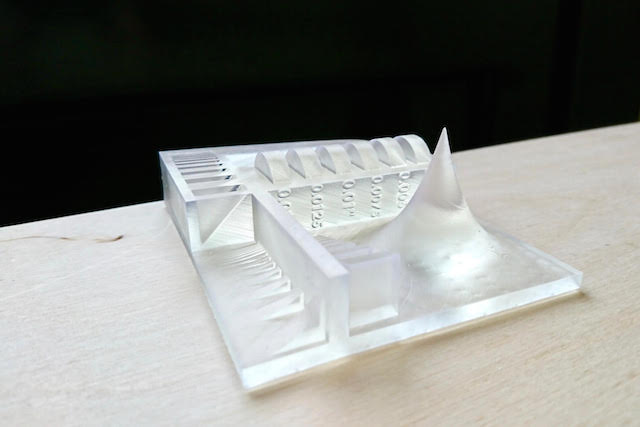
2. We made too, a printed tester for calculate angles and ramps at our printer, this model was dowloaded from Thingiverse too, where you can find a lot model for callibrated, calculates and measure previous things with each 3d Printer model :

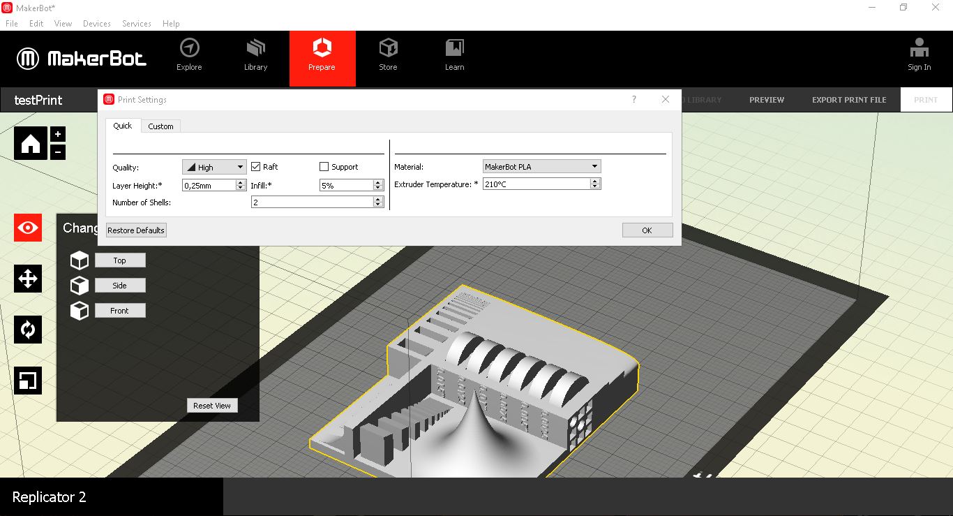
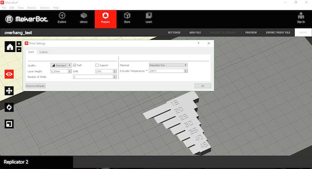
At the maker Bot software, we prepared the file before send to our SD card. The parameters used were :
SETTINGS
Machine: Makerbot Replicator 2
Material: PLA Roll Filament (1.75mm)
Layer Height: 0.20mm
Raft: No
Infill: 14%
Supports: No
Extruder Temperature: 200ºC
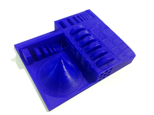
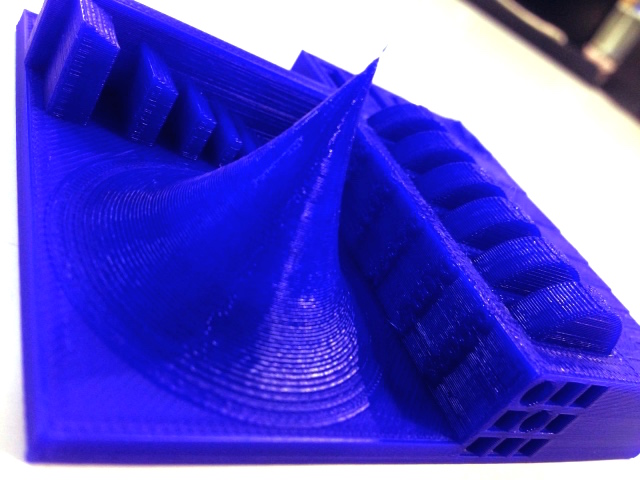
Results:


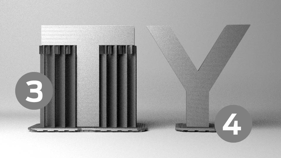
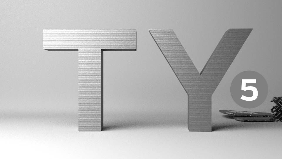
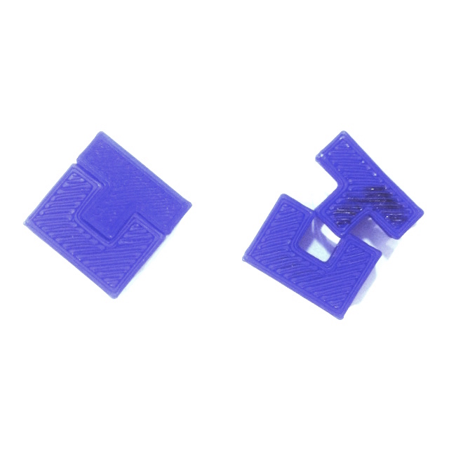
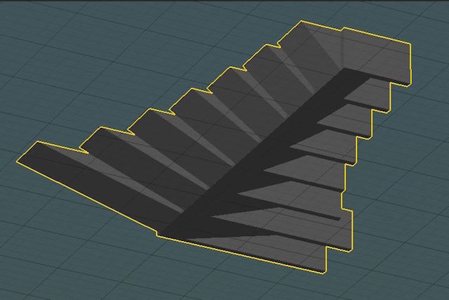
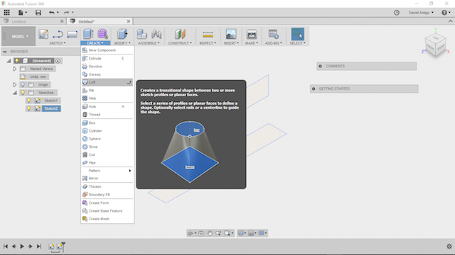
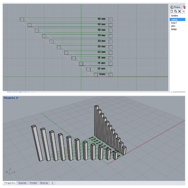
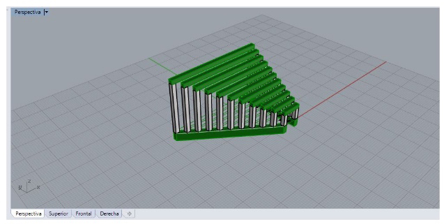
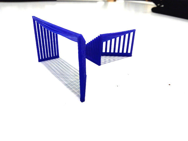
3. Another model more for learn how the layer height and the angle affect to the resolution. The dessign was made with Fusion 360º. The process was really simply.
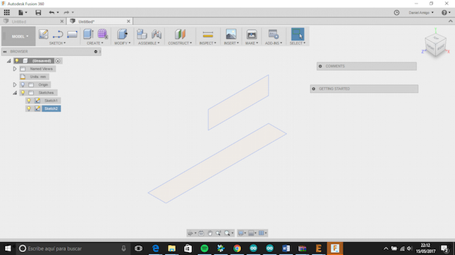
We putted 2 squares in 1 sketch :
The first in plane XZ and the second in plane YZ.
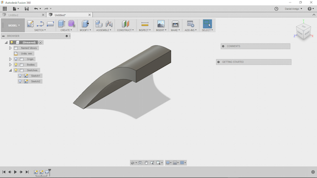
Finally, we joined with loft tool. The direction in profile 1.
Material: PLA 1,75 mm Colorfabb (Brown color).
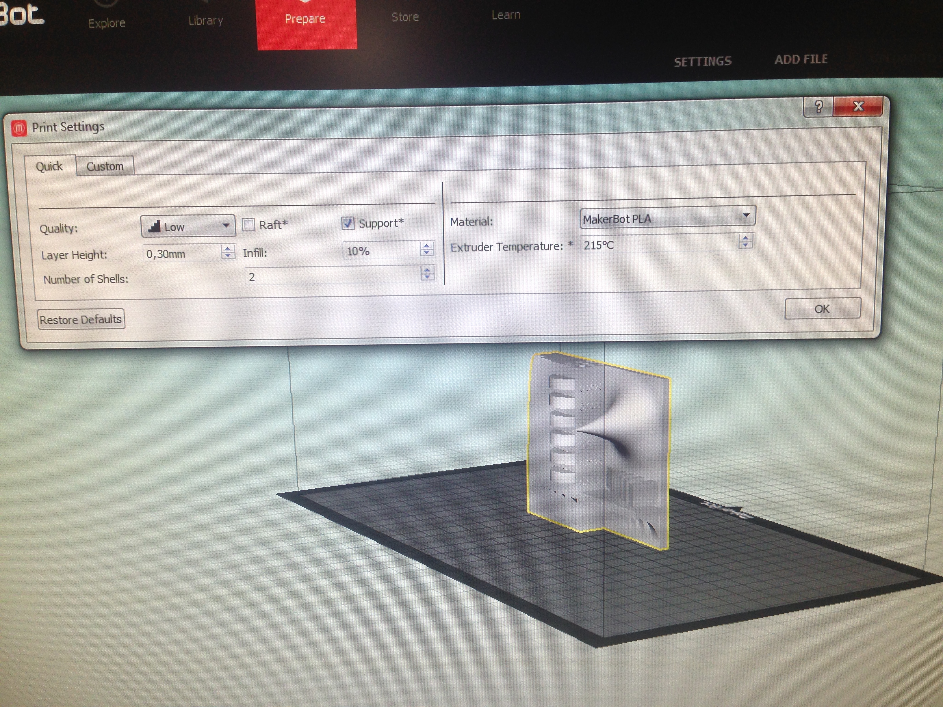
FIGURE 1 :
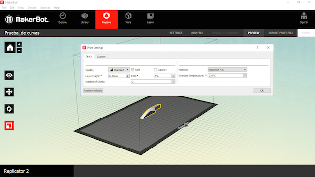
Height layer: 0.3;
Temperature: 210;
Raft: off;
Support: on;
Infill: 5%;
Number of shells: 2.
FIGURE 2 :
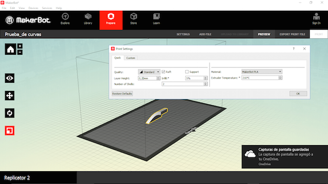
Height layer: 0.2
Temperature: 210
Raft: off
Support: YES
Infill: 5%
Number of shells: 2
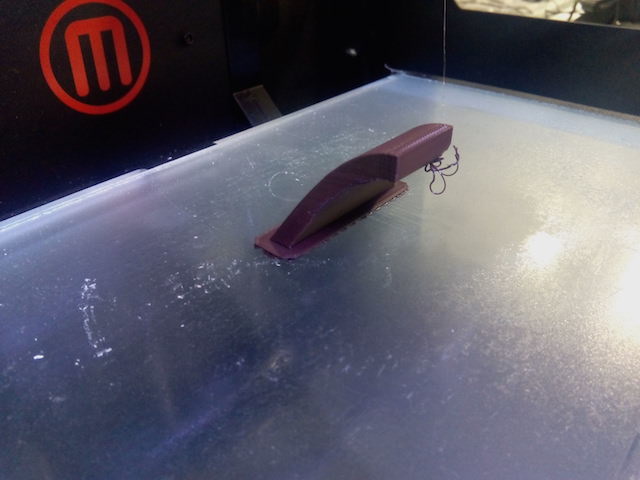
The figure 2 has better resolution than the figure 1 because less layer height makes the steps less noticeable and the air zones come out better.

TEST 3: Quality of the pieces according to the Extrusion Temperature :
For this test each one printed bit things for spent the time as better as possible testing according to more things than the temperature. For this practices we use free design or redesigned things from open design and made our own design also.
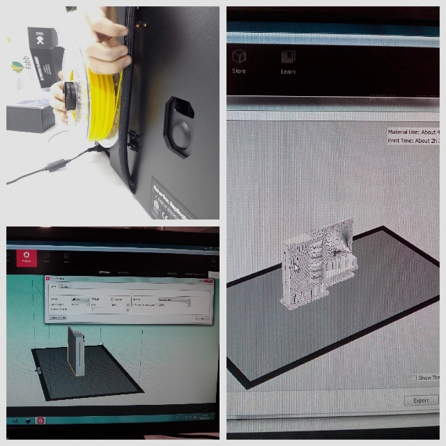
Printing Process
We had fun time preparing the maching for print the models and with the results feelting like as childs :
The Open Bracelet Design
The Open Bracelet Design
A design that practice the idea to made open non-subtractivel models was one the design made from Nervous System App which was designed for exported quick things for print like this braceletº :
You can know more about the design at Pilar´s Week Webpage where she told all about how you can print a custom bracelet based on Nervous System Designs.
The main goal was to see how the Maketbot did all of this and learn the way the object needs to be designed for printing new objects that can't be done in other ways.
After she downloaded the desing, we preparaded the .stl at MakerBot Software appliying the parameters described at Settings :
Material : PLA Filament
Layer height: 0,20 mm
Temperature: 210º
Infill : 10%
Support : NO/p>
Raft :NOCONCLUSIONS
The piece was printed as we expected with great results according to the temperature and learned us about the angles too. Probably if we print the object with more temperature the quality increase the final object.
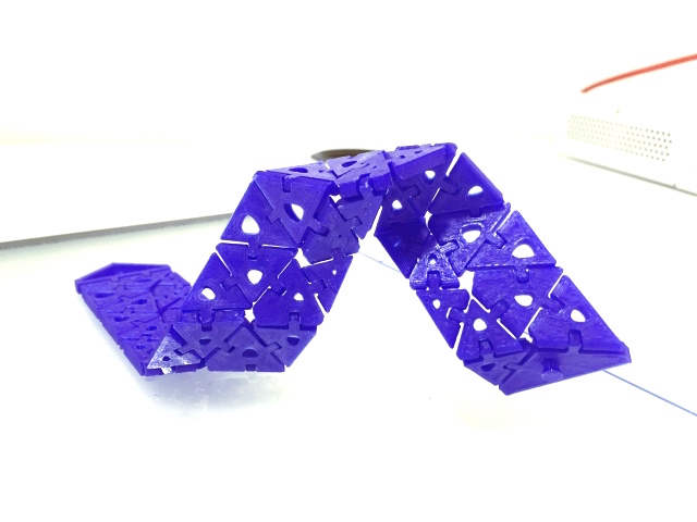
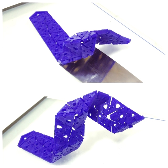
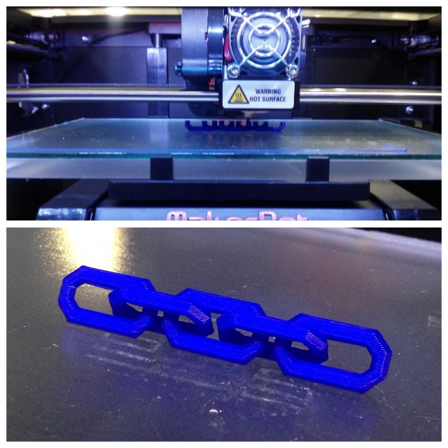
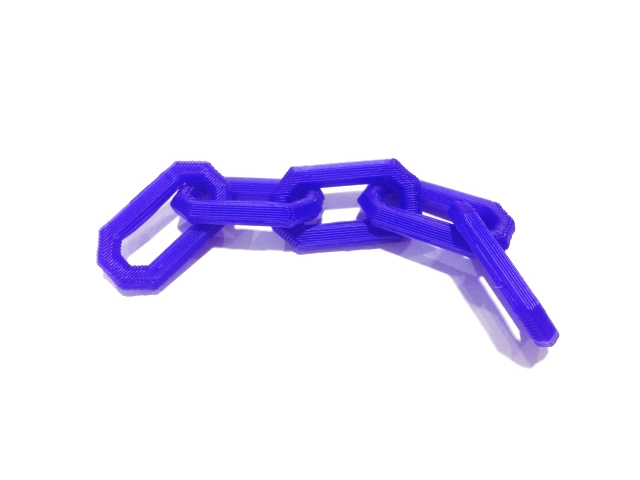
The Open Chain Design
The Open Chain Design
As some of us has never worked with a 3d printer, we chose an example from Makerbot's files to see how a non-subtractive object (such as a chain linked together with independent parts) is done.
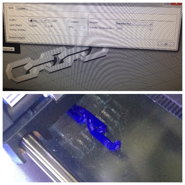
SETTINGS
Machine: Makerbot Replicator 2
Material: PLA Filament(1.75mm)
Adjustments
Layer Height: 0.30mm
Raft: No
Infill: 10%
Supports: No
Extruder Temperature: 195ºC
Print Time: 7 minutes


The way the machine has done the chain is very interesting as it opens new design strategies when creating a new object. When designing, we should think as a way of creating in a big number of finite planes added up one with the other instead of a whole object being produced at once.
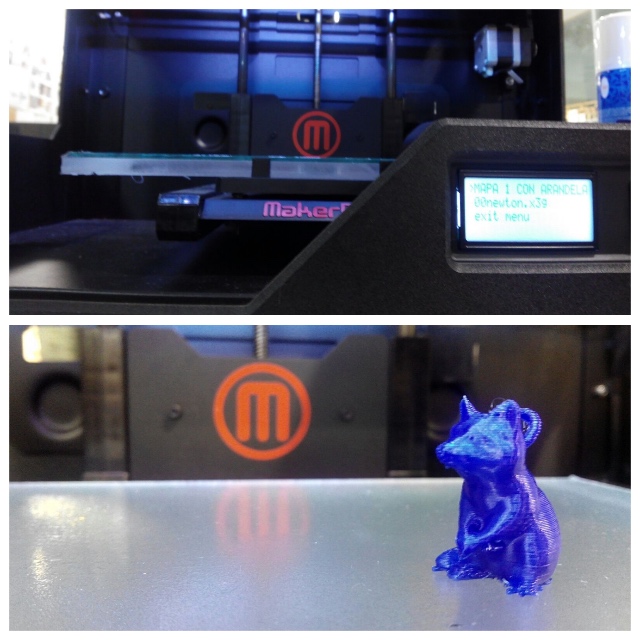
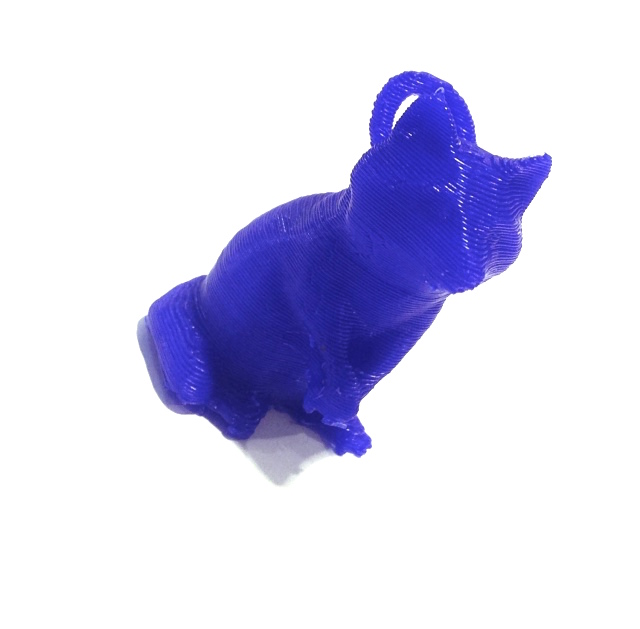
The Open Raccoon Design
The Open Raccoon Design
The purpose of this test was to see if you could add a solid from rhino to a mesh already downloaded from thingiverse and that when you enter it into makerbot, you should recognize the stl as a single object.
In addition to being one of the first tests, we wanted to see how precisely you see the details of small objects.

SETTINGS
Material: PLA Filament of 1.75mm
Parameters used:
-Layer Height: 0.25 mm
-Raft: yes
-Infill: 10%
-Supports: yes
-Extruder temperature: 215ºC


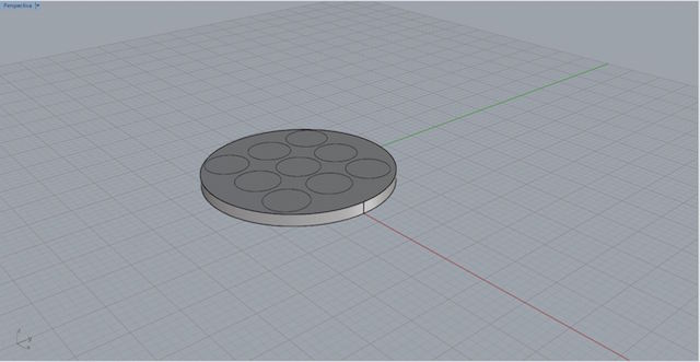
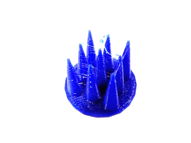
The Skewers Design
The Skewers Design
With this model we wanted to know what minimum measures could get to print with that configuration. And the minimum distance between objects, we also raised the extrusion temperature to see how it worked at 230ºc.
Software used: Rhinoceros v 5.0
Operations: Drawing, extrusion and boolean operations:
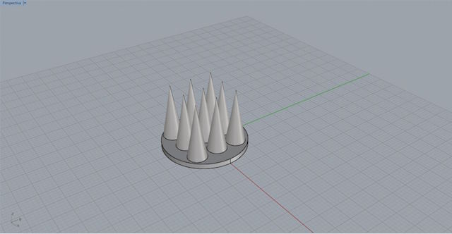
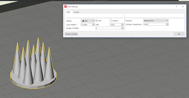
SETTINGS
-Layer Height: 0.15 mm
-Extruder temperature: 230ºC
-Raft: NO
-Infill: 15%
-Supports: NO
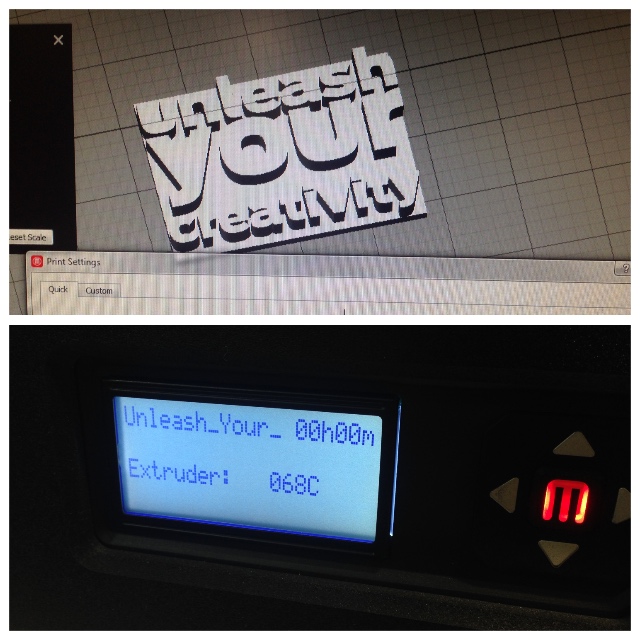
The "Unleash" open Design
The "Unleash" open Design
The idea with this test is learned how 3D printers print models with Text and letters involve.
TEST 4: Bridges
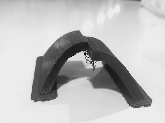
1. For began, we practice bridges designing this pieces with Rhinocerose:
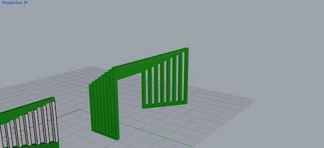
2. Preparing the file at Makerbot software :


The objective of this test is to know what distance can save without placing supports.The Parameters used were :
SETTINGS
-Layer Height: 0.25 mm
-Raft: yes
-Infill: 10%
-Extruder temperature: 215ºC

In the first test the bridges are ok , but We keep increasing distances...
Problems accounted:
There is a problem that we have not taken into account, and is that the machine is not recognizing it as a bridge.This is because the thickness is not the minimum, we will have to repeat this test by giving more thickness to the pillars.
CONCLUSIONS: The machine surprisingly continues making the bridges continuous but the threads are no longer together. They are separated and they are not resistant.
- As A group, we havent good communication this cause a waste of time during some task.
- As our instructor said : Excuses are for weaks!
WEEK CONCLUSIONS
3D Printers is a discipline for study depthly.
We learned a lot of with our replicator.
We miss some tester with another kind of Filaments.
Sometimes we won´t a pir of replicator for advance.