Procedure:
0. Assignment
1. Strategy
2. Material I need
3. Designing My Board - Schematic
4. Building My Board - Board Final Design
5. Milling The Board
6. Programming
7. My Final Project's Input Code - Strategy
8. Code Used
9. Problems Accounted
10. Download Files
0. ASSIGNMENT
Measure something: add a sensor to a microcontroller board that you have designed and read it.
LEARNING OUTCOMES
Demonstrate workflows used in circuit board design and fabrication.
Implement and interpret programming protocols.
HAVE YOU...
...described your design and fabrication process using words/images/screenshots
...explained the programming process/es you used and how the microcontroller helped you
...explained problems and how you fixed them.
...included original design files and code.
1. STRATEGY
The goal this week is to continue developing my final project. As the project is to create a lightning device that
can be moved without being touched, my idea is to create a new board connected to a sonar.
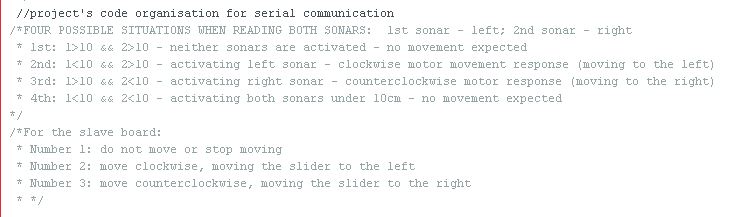
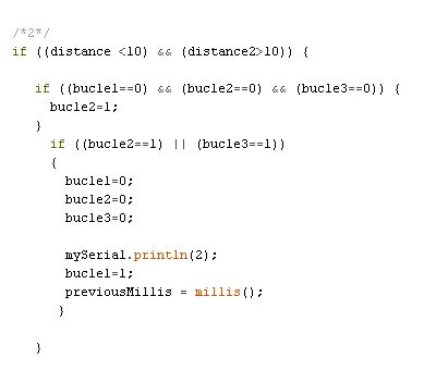
My idea is to create a program that changes the led's colour depending on the distance read by the sonar.
The reason why I have chosen a sonar and not other devices is because it can read distances.
As this device is for my drawing table, at home, I will be moving around my room constantly and I need a device
that can be activated at certain distances.
MCU I am going to use:
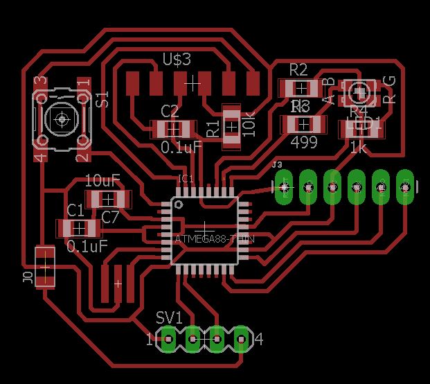
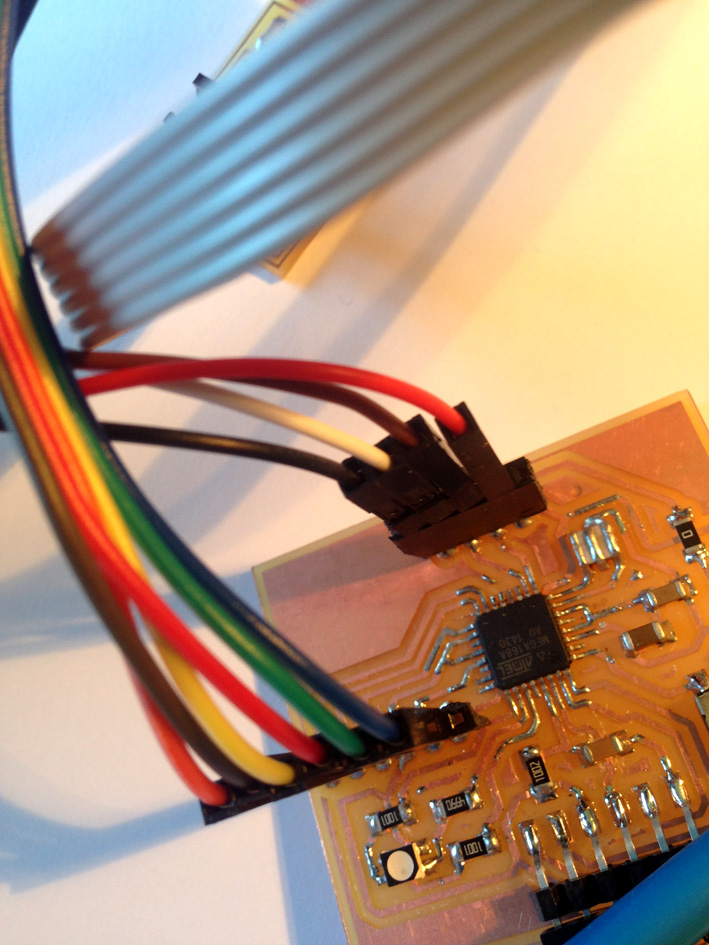
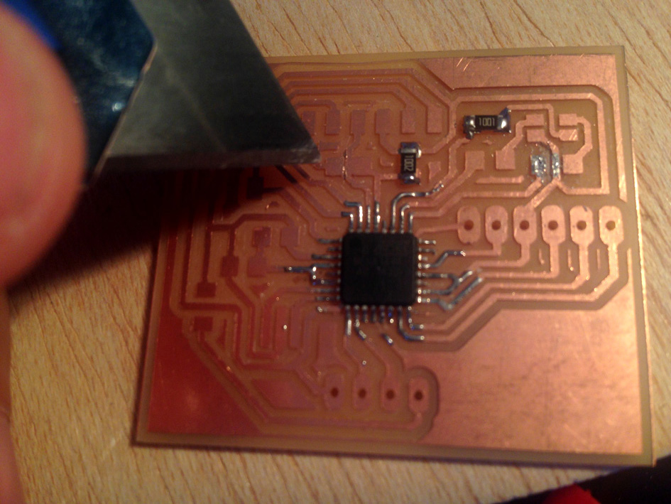
I will be using a Atmel AtMega 168 with 32 pins. The reason I chose this one is because it has more memory than the
ATiny 45 that Neil uses. Plus, in order to have as well a RGB led, I need more pins to connect the led.
My first design was done with a ATiny 44. Later on, thinking more about the functionality of my board, I decided
to change to the AtMega.
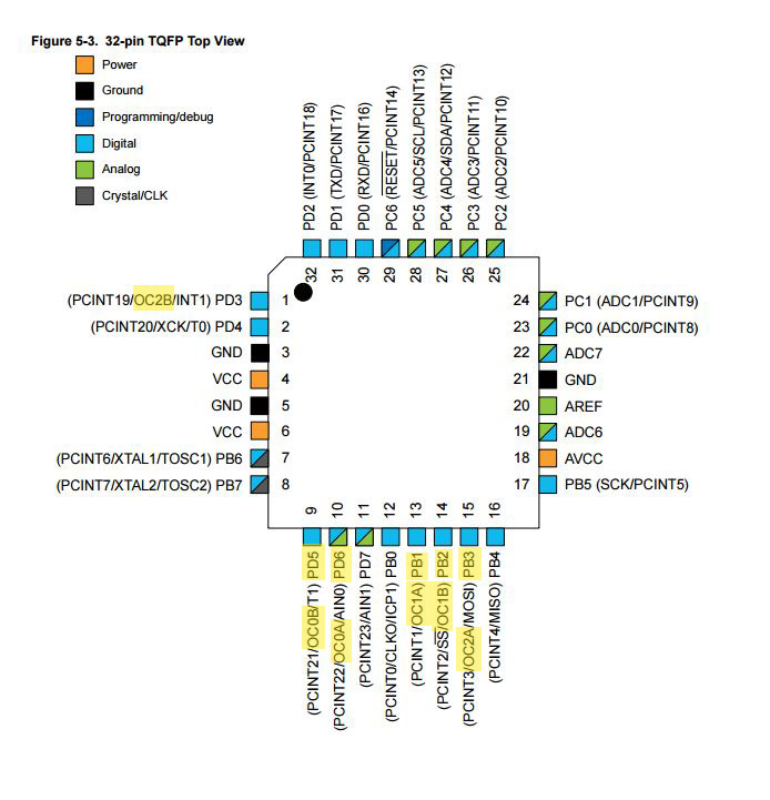
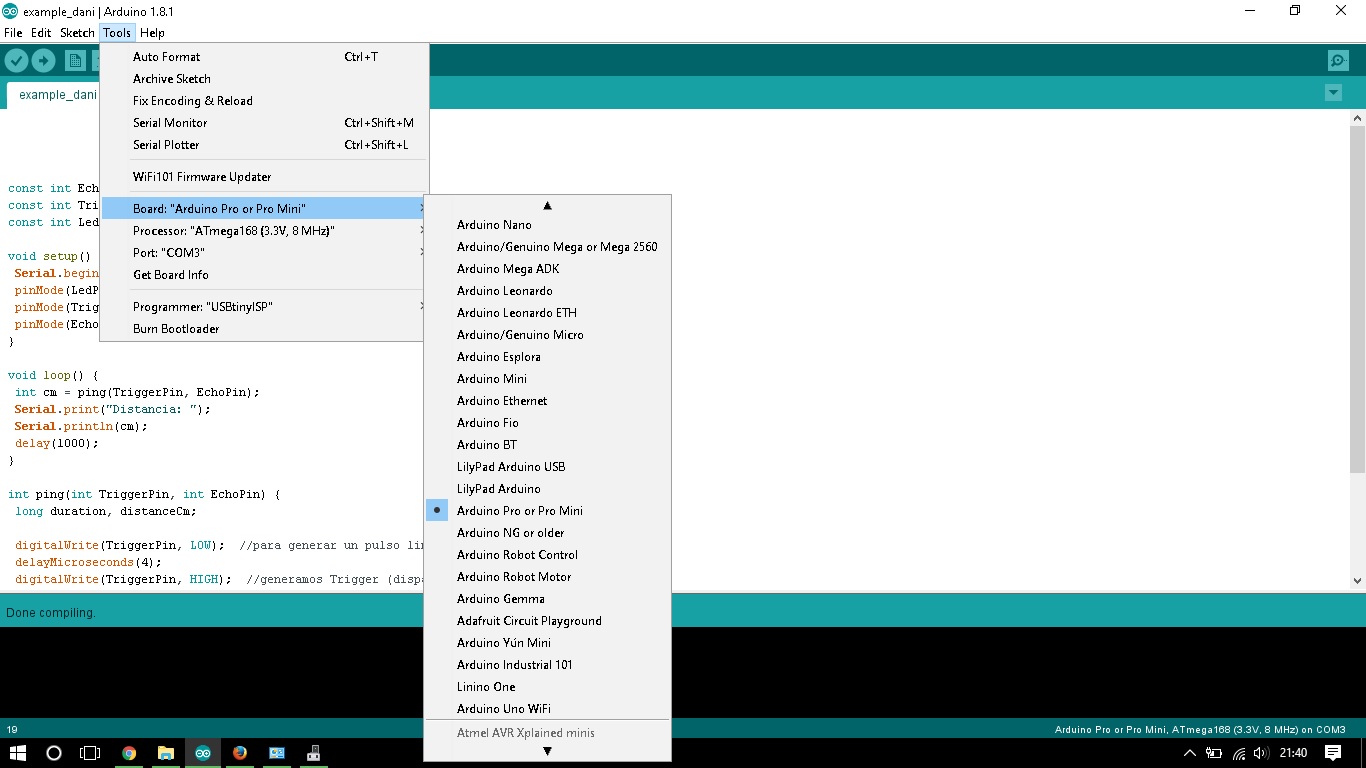
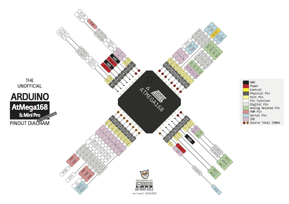
Here is the reference with arduino pins:
What pins I need to connect my ultrasonic device with my mcu?
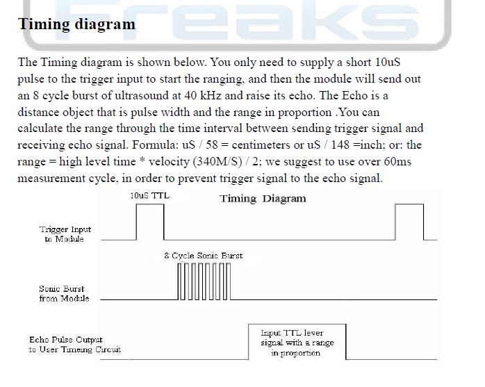
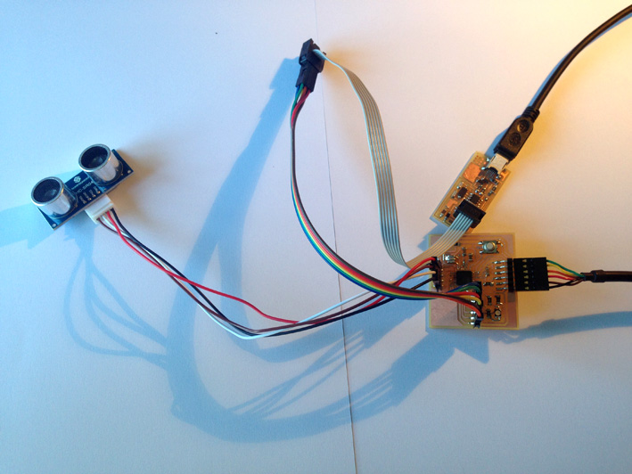
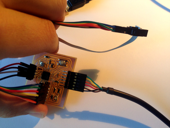
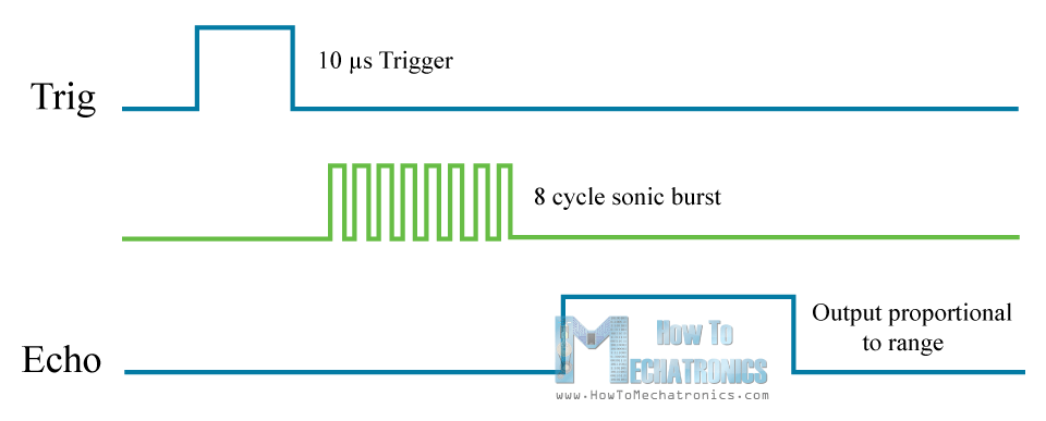
The ultrasonic sensor needs to be connected to my MCU with two
connections: the 'Trigger Pin' and the 'Echo Pin'. The 'Trigger Pin'
is connected to pin 'PD5' (or number 5) of my board, and the 'Echo Pin'
is connected to 'PD6' (or number 6). On the table below it can be seen
the different characteristics of each pin of my board:
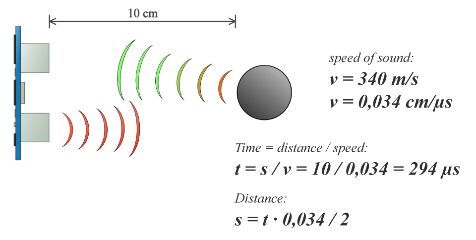
Both pins need to behave in a general way, as only one needs to
be activated for a precise moment of time and the other pin listens to
the reply. With the moment time, the mcu calculates the distance
at which the nearest object is at. A further explanation is done
later on in the
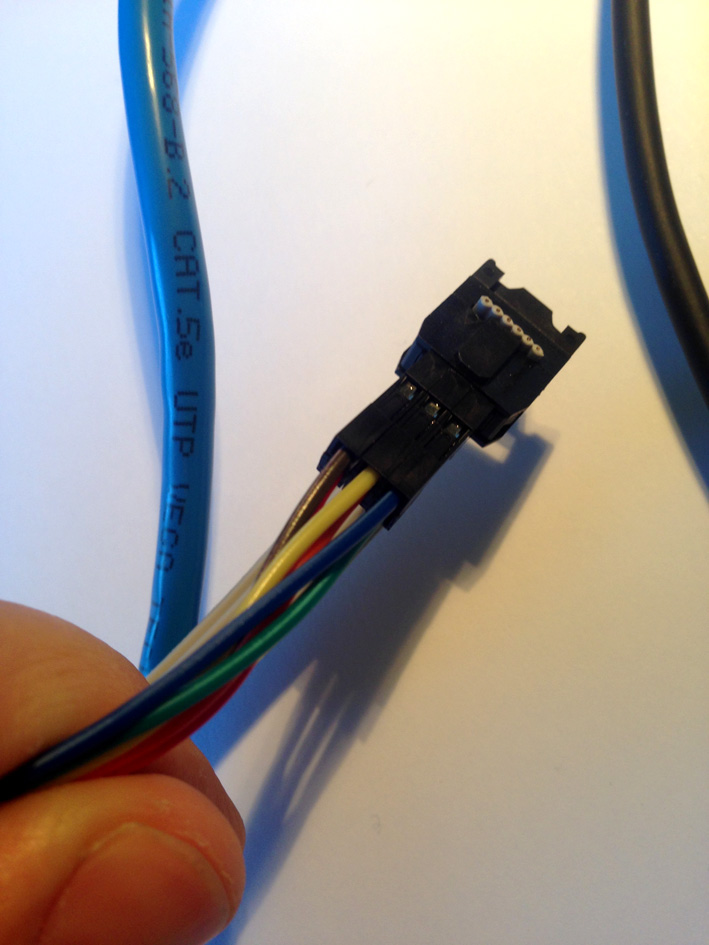
The device I will be using is the 'Ultrasonic Ranging Module HC-SR04', from Elec Freaks.
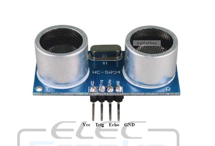
It has 4 pins: VCC, Trigger, Echo, Ground.
Technical Information: For this sonar, I do not need an extra supply as it works with a 5 volt circuit. It is perfect
for me as I need to read distances within a short range (2cm up to 4 m).
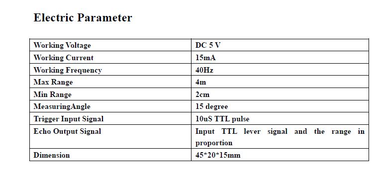
Specifications
-Operating voltage: 5V
-Working current: 16mA.
-Weight: 90g;
-Dimensions: 46 x 20.5 x 19.5 mm (thickness of anti-reverse pin socket included)
Understanding the Sonar - Company's explanation
As for the ranging principle, it is quite simple to understand: pull up the pin Trig to High thus providing high
level signals of at least 10us, so the module starts to detect and measure the distance; if an object is
detected, the ECHO pin will be High, and the duration of it being High depends on the distance detected,
thus giving the distance calculation formula: Distance = Duration of High ECHO * Speed of sound (340m/s)/2.
2. Material I need
-1MCU AtMega 168
-2 Capacitors 0.1 uF
-2 Capacitors 10 uF
-1 Capacitor 1 uF
-1 Switch/Slide
-1 RGB Led
-1 Resistor 10k
-2 Resistors 1K
-1 Resistor 499 ohms
-1 Jumper (Resistor 0 ohms)
-Jumper
-1 FTDI Male Connector
-1 Resonator 8MHz
-1 Female Connection Pad 1x06 (for the USBTinyISP Programmer)
-1 Female Connection Pad 1x04 (for the sonar)
-1 Sonar HC-SR04 + Cable with male connectors
3. Designing My Board - Schematic
In order to make my board, I had a look to the Fabacademy's archive and based my board on the FabKit's board and Neil's board.
4. Building My Board - Board Final Design
My final board design.
As everything works with the FTDI Cable supply (5 volts), no additional supply is needed. As done for output devices,
I need to change the 'Design Rules' of Eagle Software, to make sure pads on the board are not connected together.
5. Milling The Board
As in previous situations, I have used the Modela MDX-20 to create my board. Here are my PGNs ready (traces, perimeter, holes):
Uploading files to Mods:
CALCULATE
These are the windows that pop up when mods has calculated the milling paths:
SEND
When milling the board, I had several problems with mods. Although on the png file the traces are clearly separated,
mods did not interpret it in the same way, having some copper without being milled.
Although it is clearly represented on the image where the mill is going to pass, I did not notice it until
it was milled.
Using a cutter to remove the copper that I did not need:
Therefore, I had to make some manual changes + testing there was not a shortcut.
Continuing building my board
Finished! Every connection has been checked, well soldered and now I can proceed to program it.
6. Programming
This design, as the one done before (outputs), instead of soldering a 2x3 pin to the board,
I connected a pad 1x06 that connects to the USBFabIsp Programmer. Carefully, I checked which pins
correspond to what pins on the FabIsp:
Everything Connected! Let's burn the bootloader:
As it happened with outputs, now I have enough memory to burn a bootloader so once installed,
I do not need anymore the USBFabIsp Programmer.
Checking at which port it is connected:
Adjustments needed:
-Adjustments needed:
-Board: Arduino Pro or Pro Mini
-Processor: Atmega 328 (3.3V, 8 Mhz)
-Port: COM 3
-Programmer: USBTinyIsp
-BURN BOOTLOADER
ERROR
Error Message when burning the bootloader
"Arduino: 1.8.1 (Windows 10), Board: "Atmel atmega168pb Xplained mini"
avrdude: Expected signature for ATmega168P is 1E 94 0B
Double check chip, or use -F to override this check.
Error while burning bootloader.
This report would have more information with
"Show verbose output during compilation"
option enabled in File -> Preferences."
For burning the booloader, I forgot that for Arduino to read the ATMega 168 board, I needed to adjust it as an Arduino Pro or Pro Mini Board and not the one I selected.
Everything was done successfully. Although I had problems with the board, all connections are ok and ready to start the programming.
PROGRAMMING THE BOARD - CHECKING IT WORKS CORRECTLY
To start with, instead of going directly programming the Sonar, I wanted to make sure everything worked OK.
Therefore, I took the program I used with the Output Board for checking it was OK and used it with board:
Explaining the 'Test Program':
First I define the different variables for each pin (as they are constant variables, I declare them
as such). In my case, the red led is pin A4, the green led is A2 and the blue led is A3.
For the setup, I initialize each pin with the command 'pinMode'. First I start turning on the red led, then use the
command 'delay for 1000 milliseconds, turn of the red led and turn on the green led. The same process to end with the blue led, starting the loop all over again.
PROGRAMMING THE BOARD
As mentioned above, I want to create a program that changes the led's colour depending on the distance read by
the sonar. My colleague Daniel Amigo and I have both a sonar device as an input, so I did not doubt to
work together or ask him for any help with the programming.
In fact, my program is very similar to his code as we have been working together. The main difference between his
program and mine is that I interact as well with the led I have incorporated on the board.
What Does The Program Do?
The goal is to create a program that changes the RGB Led's colour depending on the distance measured. I told the board that, above 10 cm, the RGB Led has to be at {R,G,B};(150, 150, 150). If the distances measured is under those 10cm, then {R,G,B};(50, 75, 241).
How does it work?
For the sonar, I have four pins: a VCC and a GND for power, and a TRIG and ECHO
pin. The trigger fires a pulse for 10µseconds and echo reads it.
With a quick calculation, I can figure out at what distance the
obstacle read by the sonar is at:
Speed of sound: 340 m/s
When I 'digitalWrite (TRIGGERPIN, LOW) to digitalWrite (TRIGGERPIN, HIGH), I
create this new impulse. Then I continued with the command
digitalWrite (TRIGGERPIN, LOW), so it is activate once.
Visual example:
Visualisation of Trigger signal and Echo reading signal a few microseconds later:
(images thanks to mechatronics website)
The difference between when the signal is fired and then is read, is doubled
(as the echo pin only reads when the wave comes back) and with
that parameter, I multiply it by 0.034 cm/µs and then divided by 2.
Video With My Device
The first video has been taken to show how the sonar measured the
distance. The second video is my 5th attempt to change the led's
colour, failing. After reviewing the code once and again, I could
not manage to achieve the goal of changing the led's colour.
7. My Final Project's Input Code - Strategy
For my final project, I started developing the programming based on my first program. This is the final result:
I have two boards that connect with serial communication. During the programming, I had to face up several problems:
-analyse the four different situations that can take place with the two ultrasonic sensors used.
-make sure the slave board does not saturate from infinite commands sent by the master board.
-the slider's position: the system needs to know where exactly the slider is at, what distance has left to both sides.
Input Board:
Its responsibility is to analyse if there is an object (my hand) under 10cm. If this is true, then move the slider to one side. Depending on which sonar detects this obstacle, it moves to one side or the other.
The input board is the master board of this system, having the responsibility of:
-send the order to the slave board
-consider all four situations regarding the sonar's readings.
-do not saturate the slave board with orders
Just below, there are two pictures with the most important parts of the input's code. They solve what was written above.
(code for having an obstacle in sonar1, sending to the slave board number 2)
Sending The Order To The Slave Board
For the board to send the order to that slave board, it uses the command 'mySerial.println(n)'.
Number n can be:
n = 1 - Sends the order to the slave board to not move.
n = 2 - Sends the order to the slave board to move the stepper clockwise, moving the slider to the left.
n = 3 - Sends the order to the slave board to move the stepper counter clockwise, moving the slider to the right.
Analysing The 4 Possible Situations
As you can see on the picture, the first 'if()' is activated depending on the variables 'distance1' and 'distance2'. Each one of this variables have been previously declared assigning them 10. This number 10 refers to the 10cm distance where I will be operating the device. Therefore, if I have my hand under those 10cm, the board will send an order to the salve board. There are four different situations:
-Not reading anything: 'distance1>10' and 'distance2>10', both have measures above 10cm.
-One of the sensors reads an obstacle under those 10cm: 'distance1<10' and 'distance2>10'.
-The other sensor reads an obstacle under those 10cm: 'distance1>10' and 'distance2<10'.
-Both sonars read they have an obstacle under 10 cm: 'distance1<10' and 'distance2<10'.
Depending on each possible situation, the board is going to send one of the number explained before.
How Not To Saturate The Slave Boards With Too Many Commands
Just below, plus the previous image, you have the code I have used:
(code when both sonars do not have any obstacles and reassign variables 'bucle1', 'bucle2' and 'bucle3'.)
For the board not to send infinite commands, I have used the function 'millis()' to make sure that same command is not repeated all the time. I declare the variable 'interval' (take a look to the code, the image only shows some of it), where I decide how much time it needs to pass so the board can send the same order again.
Initially, 'bucle1', 'bucle2' and 'bucle3' are the variables that make it possible to not send all the time the same command, and the three of them are assigned number 0.
The way it works is very simple: once activated a possible situation, one of the variables changes from 0 to 1. When the loop starts over again, for the same possible situation, there is an initial 'if()' function. This if() function reads: if one of the two other variables are 1, the same command can be sent again, if not, continue with the next part of the code.
Here is the tricky part, I need to wait for the interval to take place so the variables go back to 0 and the same command can be sent again.
8. Code Used
Boarding Test With RGB Led
const int LED_ROJO = A4; //Pin connected to red led
const int LED_VERDE = A2; //Pin connected to green led
const int LED_AZUL = A3; //Pin connected to blue led
void setup() {
// led's initialitation
pinMode(LED_ROJO, OUTPUT);
pinMode(LED_VERDE, OUTPUT);
}
void loop() {
analogWrite(LED_ROJO, 0); //Red Colour ON
delay(1000);
analogWrite(LED_ROJO, 255); //Red Colour OFF
analogWrite(LED_VERDE, 0); //Green Colour ON
delay(1000);
analogWrite(LED_VERDE, 255); //Green Colour OFF
analogWrite(LED_AZUL, 0); //Blue Colour ON
delay(1000);
analogWrite(LED_AZUL, 255); //Blue Colour OFF
delay(1000);
}
MY PROGRAM: MEASURING DISTANCE WITH MY PROGRAM
//declaring rgb led pins
const int LedPinGreen = A2;
const int LedPinRed = A4;
const int LedPinBlue=A3;
//declaring variables sonar pins
const int Echo = 6;
const int Trigger = 5;
void setup() {
Serial.begin(9600);
pinMode(LedPinGreen, OUTPUT);//rgb led
pinMode(LedPinRed, OUTPUT);
pinMode(LedPinBlue, OUTPUT);
pinMode(Trigger, OUTPUT); //sonar pins
pinMode(Echo, INPUT);
}
void loop() {
int cm = ping(Trigger, Echo);
Serial.print("Distancia: ");
Serial.println(cm);
delay(1000);
}
int ping(int Trigger, int Echo) {
long duration, distanceCm;
digitalWrite(Trigger, LOW); //para generar un pulso limpio ponemos a LOW 4us
delayMicroseconds(4);
digitalWrite(Trigger, HIGH); //generamos Trigger (disparo) de 10us
delayMicroseconds(10);
digitalWrite(Trigger, LOW);
duration = pulseIn(Echo, HIGH); //medimos el tiempo entre pulsos, en microsegundos
distanceCm = duration * 10 / 292/ 2; //convertimos a distancia, en cm
return distanceCm;
if(distanceCm>'10'){
analogWrite(LedPinRed,150);// if the distance of the distance sensor is bigger than 10cm, rgb led at (150, 150, 150)
analogWrite(LedPinGreen,150);
analogWrite(LedPinBlue, 150);
}
else{
analogWrite(LedPinRed,50);// if the distance of the distance sensor is smaller than 10cm, rgb led at (50, 75, 241).
analogWrite(LedPinGreen,75);
analogWrite(LedPinBlue, 241);//
}
}
My Final Project - Input Code
#include <SoftwareSerial.h>
#include <NewPing.h> //including library for ultrasonic sensor
#define TRIGGER_PIN 5 // pin that send a signal
#define ECHO_PIN 6 // pin that receive the signal
#define TRIGGER_PIN2 8 // pin that send a signal
#define ECHO_PIN2 7 // pin that receive the signal
#define MAX_DISTANCE 400 // max distance that the sensor will read
//initializing both sonars
NewPing sonar(TRIGGER_PIN, ECHO_PIN, MAX_DISTANCE); // establish the new ping telling which are the pins and the max distance
NewPing sonar2(TRIGGER_PIN2, ECHO_PIN2, MAX_DISTANCE); // establish the new ping telling which are the pins and the max distance
//initializing software serial
SoftwareSerial mySerial(0, 1); //Tx and Rx pins (respectivamente) - cambiado, originalmente (0,1)
//declaring led variable
int redPin = A4; // Red Led Pin
unsigned long rxTime; //define variable sensor 1
unsigned long rxTime2; //define variable sensor 2
float distance;
float distance2;
int bucle1=0;
int bucle2=0;
int bucle3=0;
unsigned long previousMillis;
unsigned long currentMillis;
const long interval = 1500;
/*float definition:
* is a number that has a decimal point. It is used to approximate analog and continuous values
* because they have greater resolution than integers. Floating numbers can be as large as
*3.4028235E+38 and as low as -3.40282335E+38.
*32-bit storage (4 bytes of information)
*6-7 digits of precision
*
*/
void setup() {
// put your setup code here, to run once:
//beginning baud rate for serial communication
mySerial.begin(9600);
//pin activation for sonar1
pinMode(ECHO_PIN,INPUT);
pinMode(TRIGGER_PIN,OUTPUT);
//pin activation for sonar2
pinMode(ECHO_PIN2, INPUT);
pinMode(TRIGGER_PIN2, OUTPUT);
//pin activation for red led
pinMode(redPin, OUTPUT); // sets the pins as output
}
void loop() {
// SONAR 1 READ
// put your main code here, to run repeatedly:
digitalWrite(TRIGGER_PIN, HIGH);
delayMicroseconds(10);
digitalWrite(TRIGGER_PIN, LOW);
rxTime = pulseIn(ECHO_PIN, HIGH); //read the Receive time
distance = (float)rxTime * 34 / 2000.0; //Converted into a distance ,cm
// SONAR 2 READ
digitalWrite(TRIGGER_PIN2, HIGH);
delayMicroseconds(10);
digitalWrite(TRIGGER_PIN2, LOW);
rxTime2 = pulseIn(ECHO_PIN2, HIGH); //read the Receive time
distance2 = (float)rxTime2 * 34 / 2000.0; //Converted into a distance ,cm
/*FOUR POSSIBLE SITUATIONS WHEN READING BOTH SONARS: 1st sonar - left; 2nd sonar - right
* 1st: 1>10 && 2>10 - neither sonars are activated - no movement expected
* 2nd: 1<10 && 2>10 - activating left sonar - clockwise motor movement response (moving to the left)
* 3rd: 1>10 && 2<10 - activating right sonar - counterclockwise motor response (moving to the right)
* 4th: 1<10 && 2<10 - activating both sonars under 10cm - no movement expected
*/
//motor stepper messages
/*For the slave board:
* Number 1: do not move or stop moving
* Number 2: move clockwise, moving the slider to the left
* Number 3: move counterclockwise, moving the slider to the right
* */
/*2*/
if ((distance <10) && (distance2>10)) {
if ((bucle1==0) && (bucle2==0) && (bucle3==0)) {
bucle2=1;
}
if ((bucle2==1) || (bucle3==1))
{
bucle1=0;
bucle2=0;
bucle3=0;
mySerial.println(2);
bucle1=1;
previousMillis = millis();
}
}
/*3*/
else if((distance>10) && (distance2<10)) {
if ((bucle1==0) && (bucle2==0) && (bucle3==0)) {
bucle3=1;
}
if ((bucle1==1) || (bucle3==1)){
bucle2=0;
bucle1=0;
bucle3=0;
mySerial.println(3);
bucle2=1;
previousMillis=millis();
}
}
/*ambas*/
else if ((distance <10) && (distance<10)) {
if ((bucle1==0) && (bucle2==0) && (bucle3==0)) {
bucle1=1;
}
if((bucle2==1) || (bucle3==1))
{
bucle3=0;
bucle1=0;
bucle2=0;
mySerial.println(1);
bucle3=1;
previousMillis=millis();
}
}
else if((distance > 10) && (distance2 >10)) {
currentMillis = millis();
if (currentMillis - previousMillis >= interval) {
bucle1=0;
bucle2=0;
bucle3=0;
}
}
}
9. Problems Accounted
Milling The Board
As mentioned above, I solved the problem of not milling correctly by with a cutter
cutting those parts that were not meant to be there. I successfully
did that, making sure everything was connected together.
Forgetting To Connect My Programmer To Burn The Bootloader
A common mistake that sometimes I forget.
Failing with the 1st Program
Failing at what my initial program (changing the RGB Led colour depending on the distance measured). It seems as if the code is correct. Further investigation is needed here. The reason why I did not continue with it is because I started developing my final project.