Procedure:
0. Assignment
1. Software Needed
2. Buying the different components for my board
3. Board Design: Schematic Diagram
4. Board Design: Board
5. Milling the Board
6. Testing The Board
7. Problems Accounted 8. Download Files
0. Assignment
Redraw the echo hello-world board, add (at least) a button and LED (with current-limiting resistor), check the design rules, make it (if you have time this week, test it).
optional: simulate its operation. Measure its operation
LEARNING OUTCOMES
Select and use software for circuit board design
Demonstrate workflows used in circuit board design
HAVE YOU...
...shown your process using words/images/screenshots
...explained problems and how you fixed them, including how you worked with design rules for milling (DRC in EagleCad and KiCad)
...included original design files (Eagle, KiCad, Inkscape, .cad - whatever)
...NB. Also, if you make a board and it doesn't work; franken-hack that board (with jumper wires etc) until it does work, then make a new one with the knowledge you have gained.
1. Software Needed
This week I am doing an 'Echo Hello-World' board version, with 3 leds (one red, one blue, one white) and one button
(switch).
Before starting with the board, first I need to download Autodesk Eagle Software and learn how to
use it with SparkFun Tutorials.
Downloading Eagle Software
Tutorial done:
Tutorial done:
The tutorial goes through all the design process for a board to be milled from the beginning to the end. It is a two step
process, where you have a first part were you draw a schematic design, where you know how the traces connect one
with the other, and a second part, where you physically position each component on the board and create the final
traces that are going to be milled.
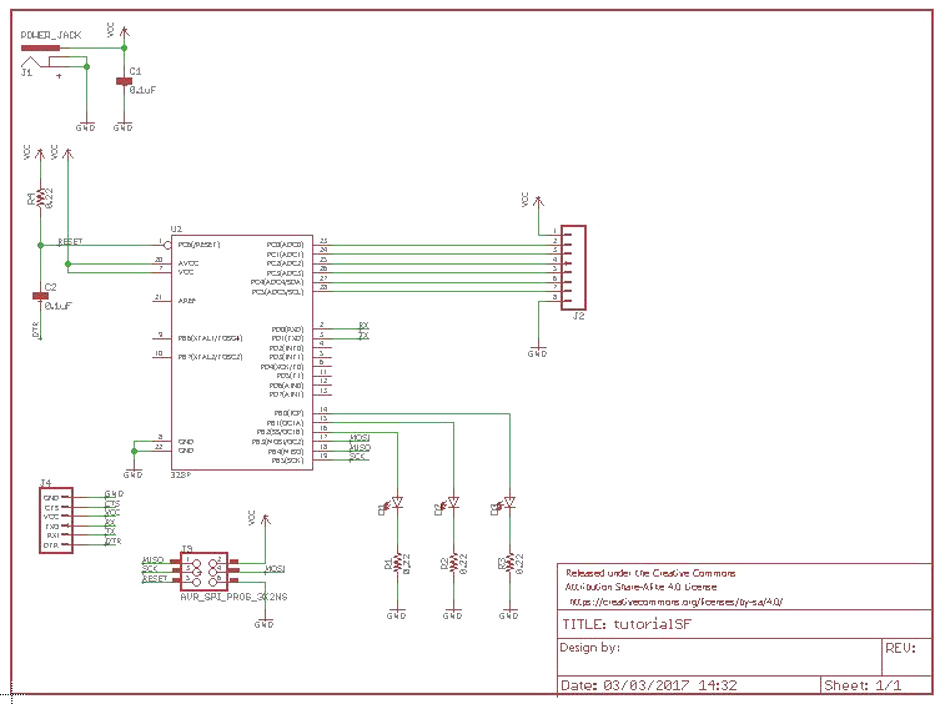
Example of the schematic done on the tutorial:
Complete Schema:
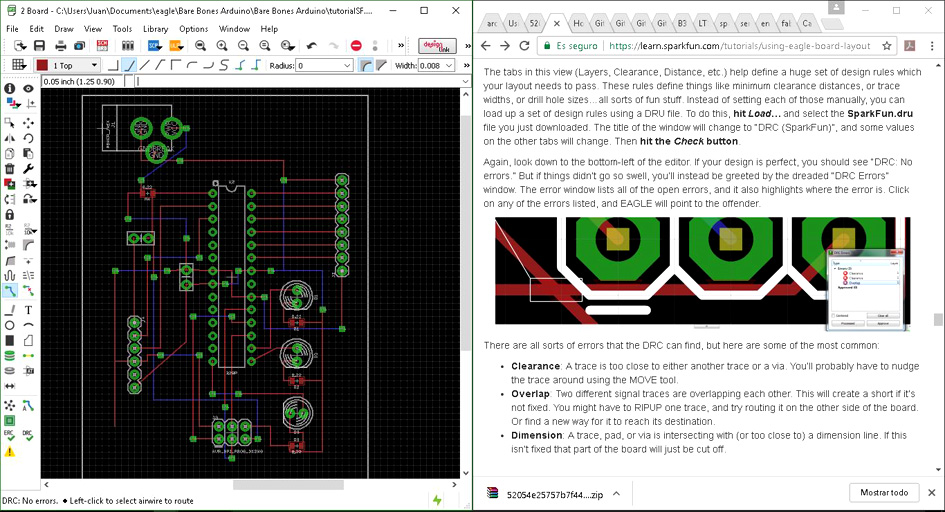
Example of the board done on the tutorial:
Tutorial DONE!
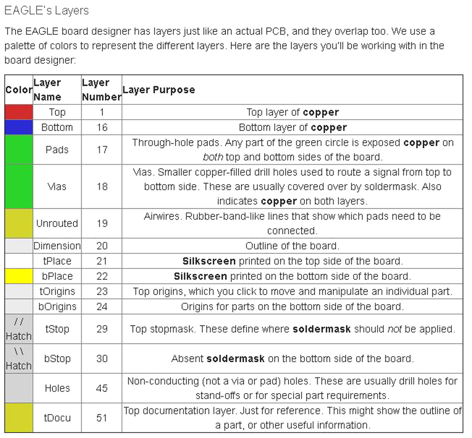
Here is a key image to understand different colour on Eagle:
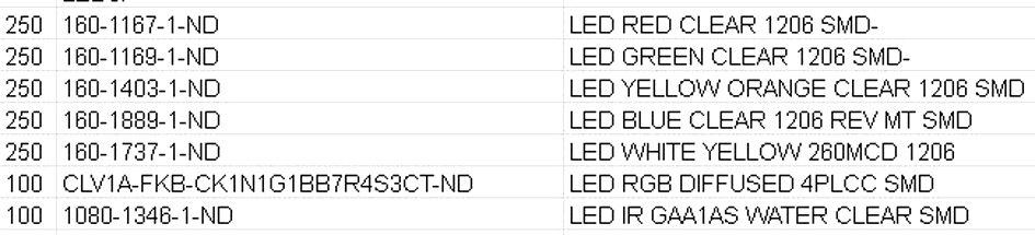
2. BUYING THE DIFFERENT COMPONENTS FOR MY BOARD
Before heading up and buy all the components, first I need to know which resistor goes with what Led. What I did was enter
fablab's inventory and take its reference, then go to www.digikey.com and take a look to the mechanical properties of each
one of them.
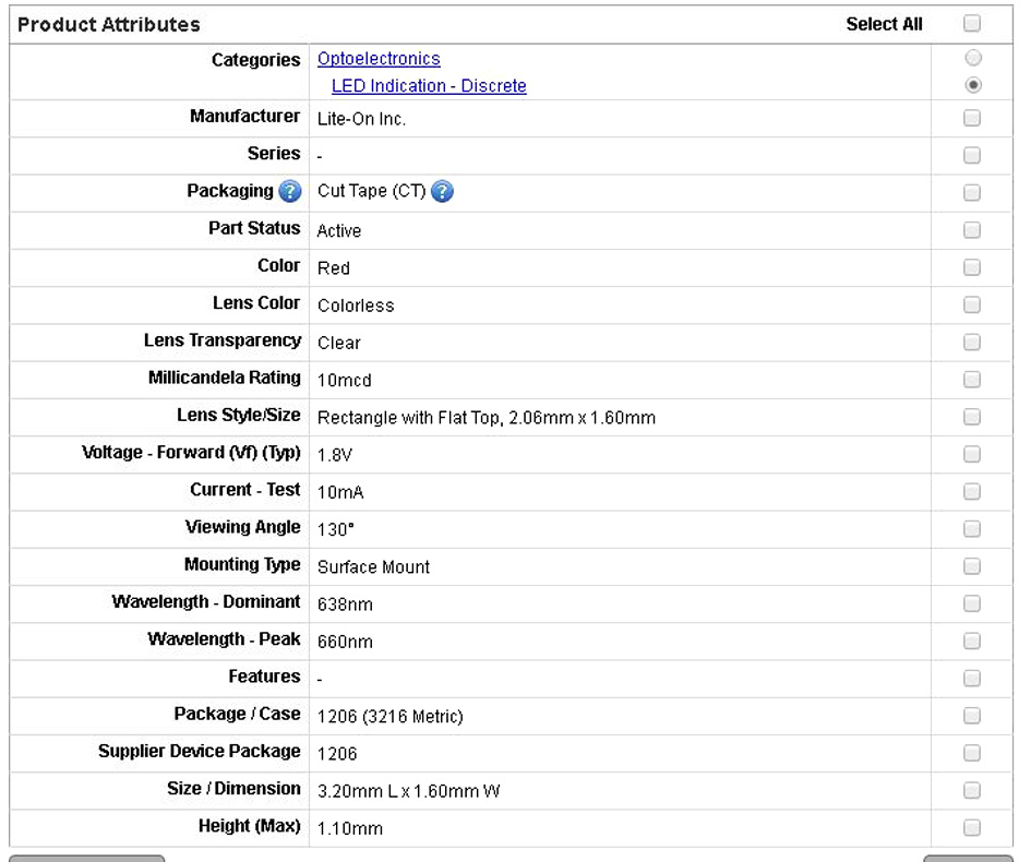
Red Led:
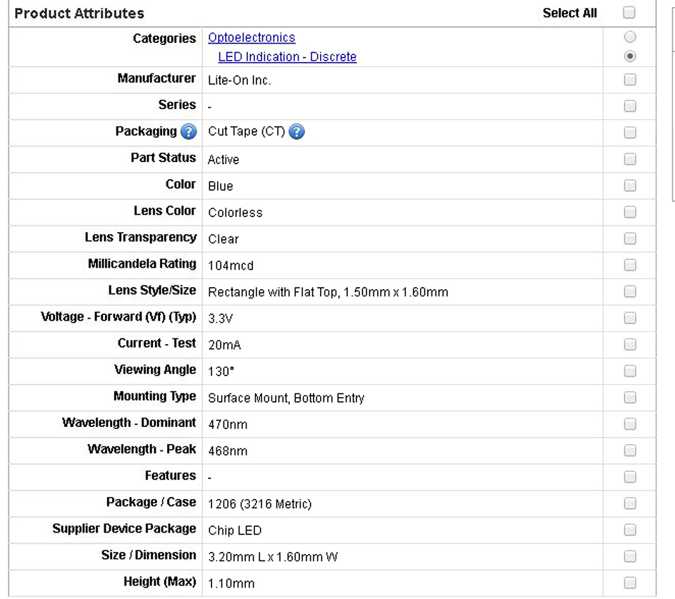
Blue Led:
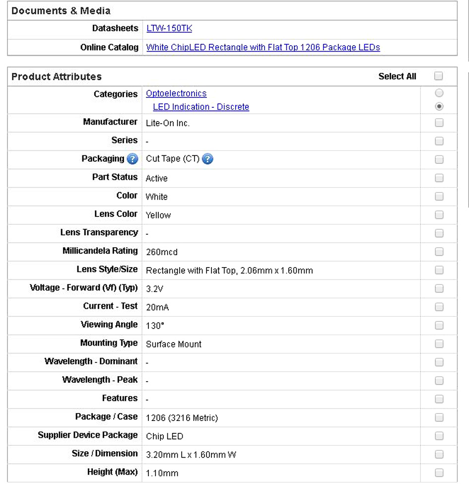
White Led:
Then, using the basic formulas of electricity:
Voltage (v) = Intensity (A) x Resistance (ohms)
Power (W) = Intensity² (A) x Resistance (ohms)
Calculating Red Led's Resistance:
Voltage needed: 1.8 V
Current needed: 10mA
If the board has a voltage of 5 volts, I need to reduce it to 1.8 V.
Voltage Difference needed = Intensity x Resistance
(5 - 1.8) V = 10 mA x R
3.2V / 0.01 A = 320 ohms
At least, I need 320 ohms for the red led to work correctly. Therefore, I will use 499 ohms resistor.
Calculating Blue Led's Resistance
The blue led needs 3.3 volts to operate correctly
Current needed: 20 mA
(5 - 3.3) V = 10mA x R
1.7 V / 0.02 A = 85 ohms
At least, I need 85 ohms for the blue led to work correctly. Therefore, I will use the 100 ohms resistor.
Calculating White Led's Resistance
The white led needs 3.2 volts to operate correctly.
Current needed: 20mA
(5 - 3.2) V = 10 mA x R
1.8 V / 0.02 = 90 ohms
At least, I need 90 ohms for the white led to work correctly. Therefore, I will use the 100 ohms resistor.
Components I need for my board:
1 ATTiny 44 microcontroller
1 Capacitor 1uF
1 FTDI header + Cable
2 Resistor 100 ohm
1 Resistor 499 ohm
1 Resistor 10K
One 2x3 pin header
1 Resonator 20MHz
1 Led 1.8V - Red
1 Led 3.2V - White
1 Led 3.3V - Blue
1 Switch/Slide
3. Board Design: Schematic Diagram
Now I can start designing my new board based on the echo hello-world board. This is my schema done:
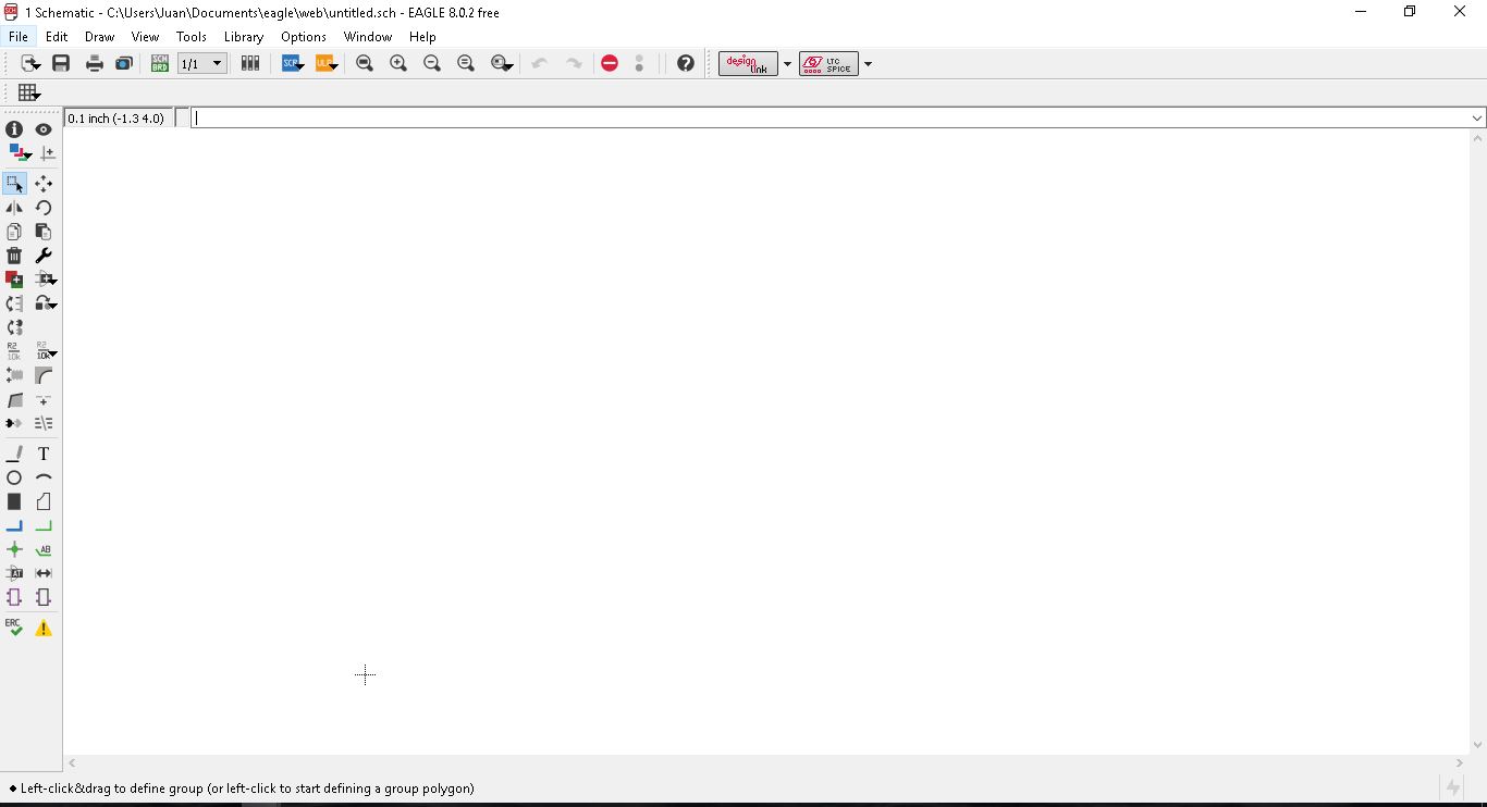
I start opening eagle:
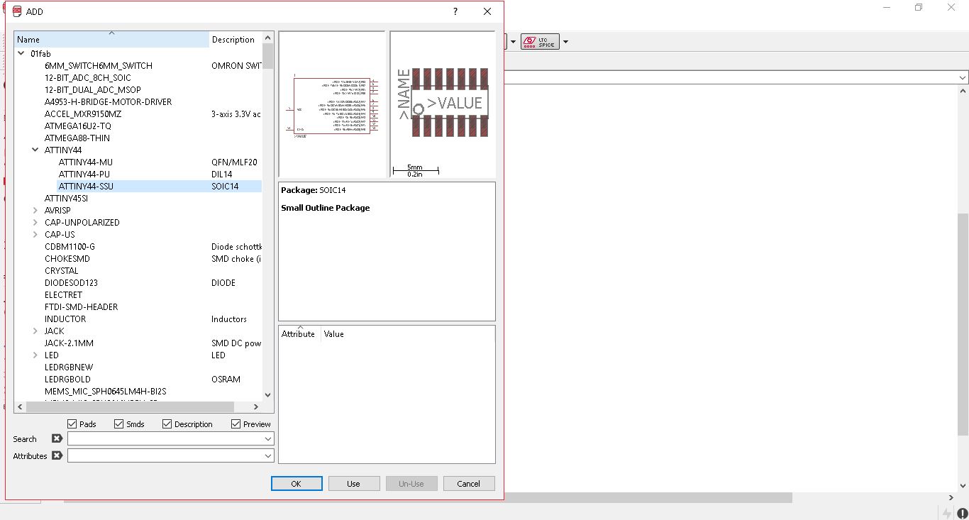
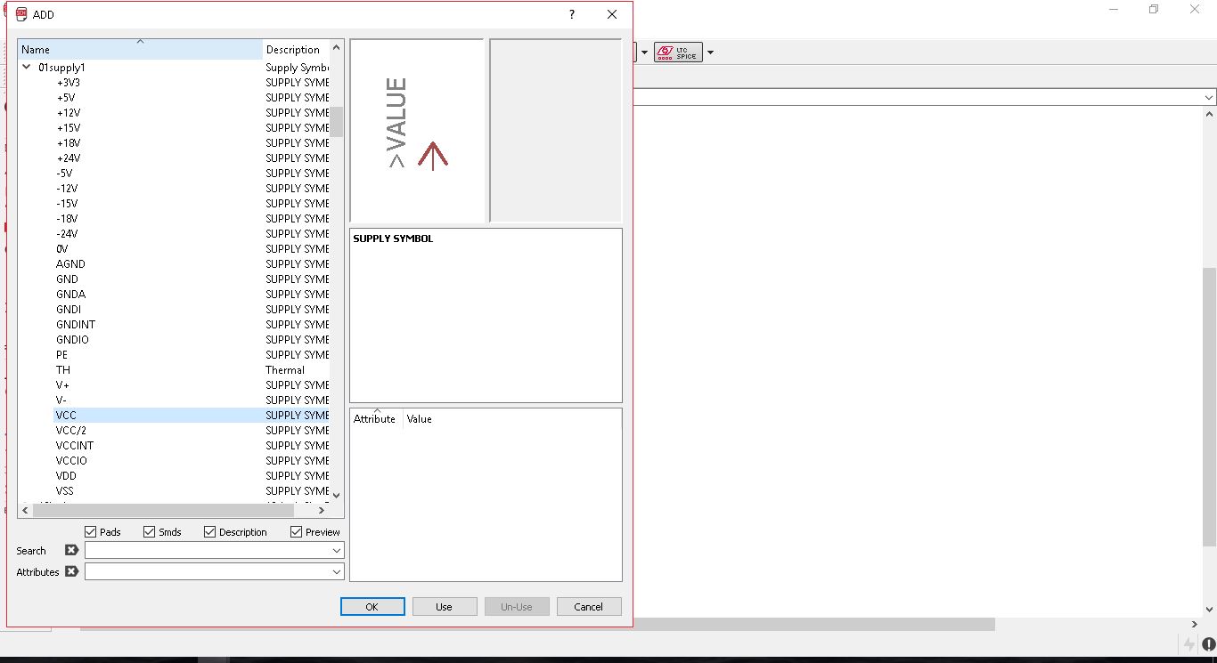
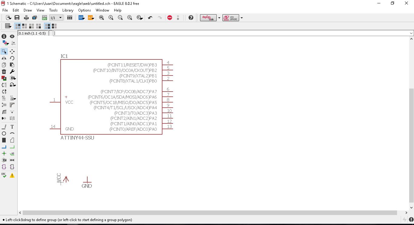
First I need to have the Mcu loaded into the file so I can start connecting different components with it, plus, the VCC and the GND connections. To open the 'add' menu, I just need to enter 'ADD' + Enter.
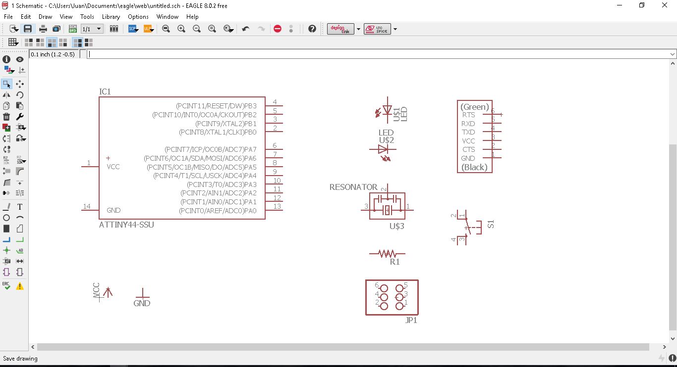
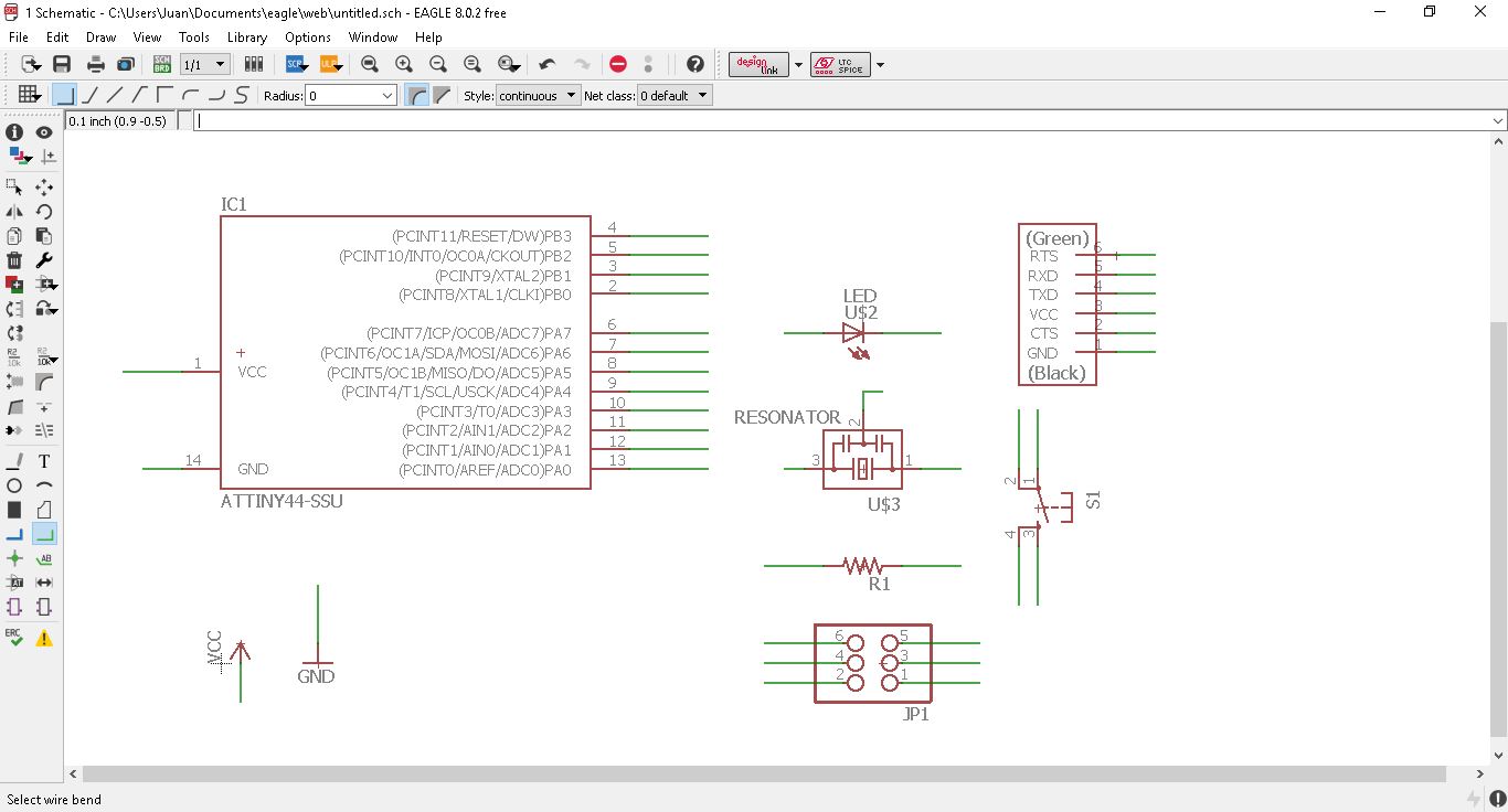
With the same method of adding, I will start adding different components: the Red Led, the resonator, the 2x3 pins, the FTDI Hearder, the button and the resistors:
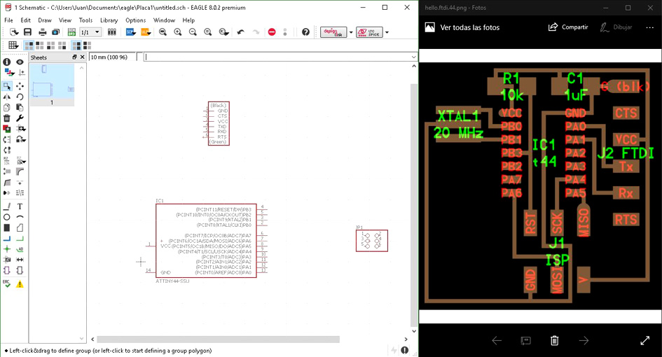
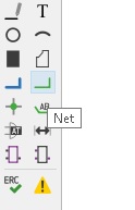
Now it is turn to connect all the different components to the board. To make it happen, I will select the command 'Net
My activating it, I can join with a green line all the different pins
from the components to the Mcu and the VCC and GND. One of the
advantages of the schematic layout of eagle is that you do not
have join physically the green lines. The only thing is needed
is to name each one of them and automatically, the program links
them for you. Here there are two pictures, the first one showing
the lines before being named and the second, being linked one with
the other.
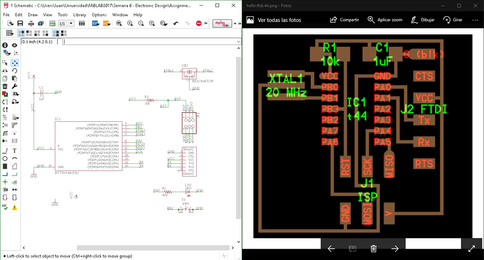
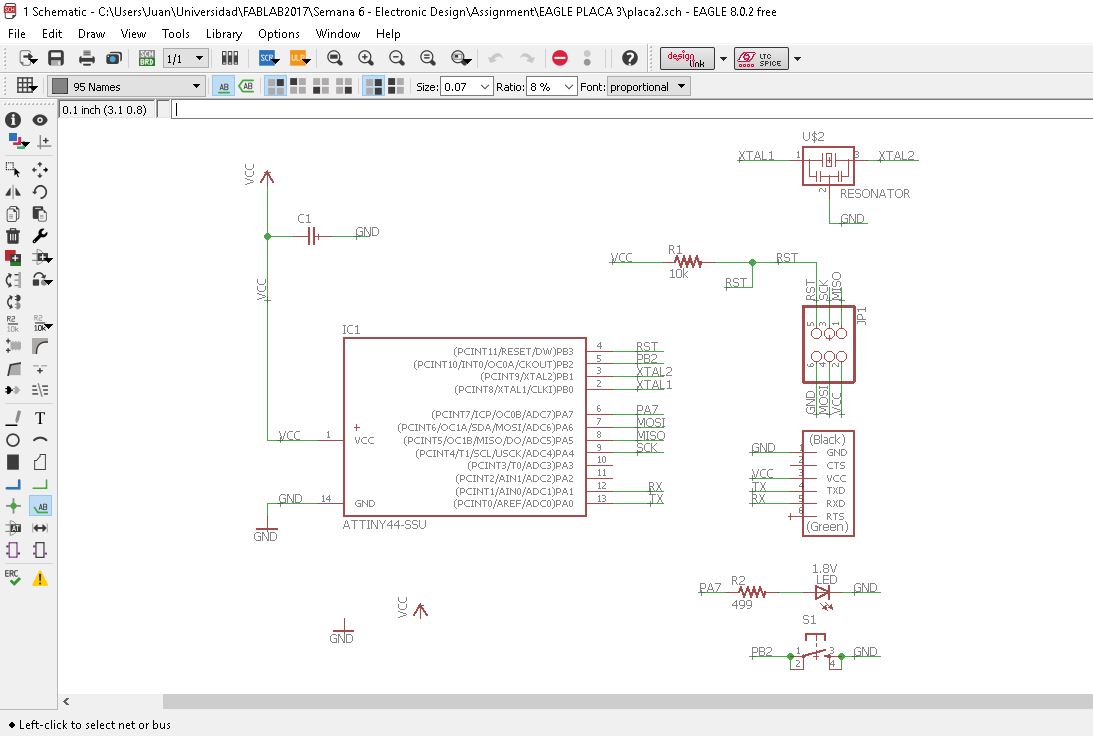
With the command 'Name', you name each component and each line what you want. With the command 'Label', you show onscreen the name of the particular line. This is how it looked when I finished naming and organising everything:
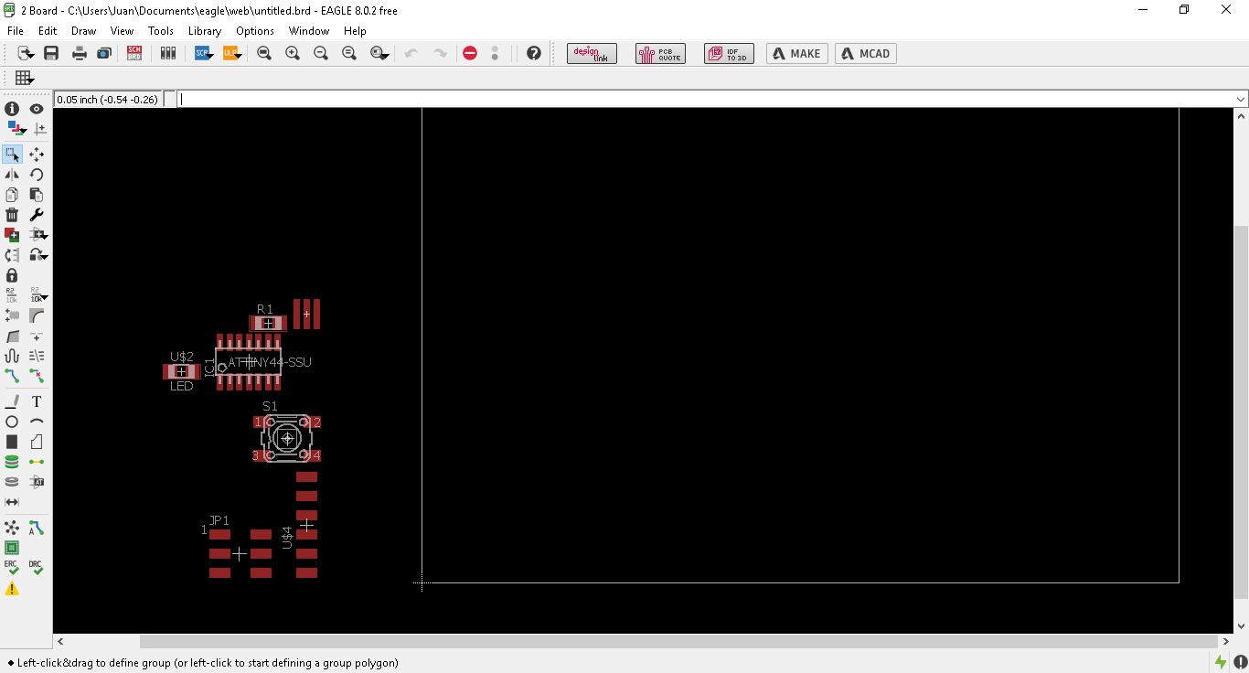
Now I have everything ready to go to the second part of the designing process: the board. The program automatically generates the board with its links (in yellow). It shows physically and on scale which pin is connected to what.
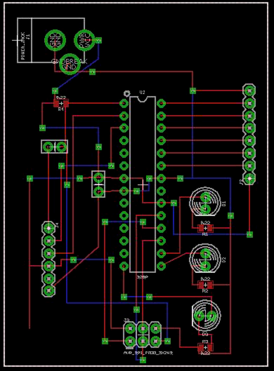
4. Board Design: Board
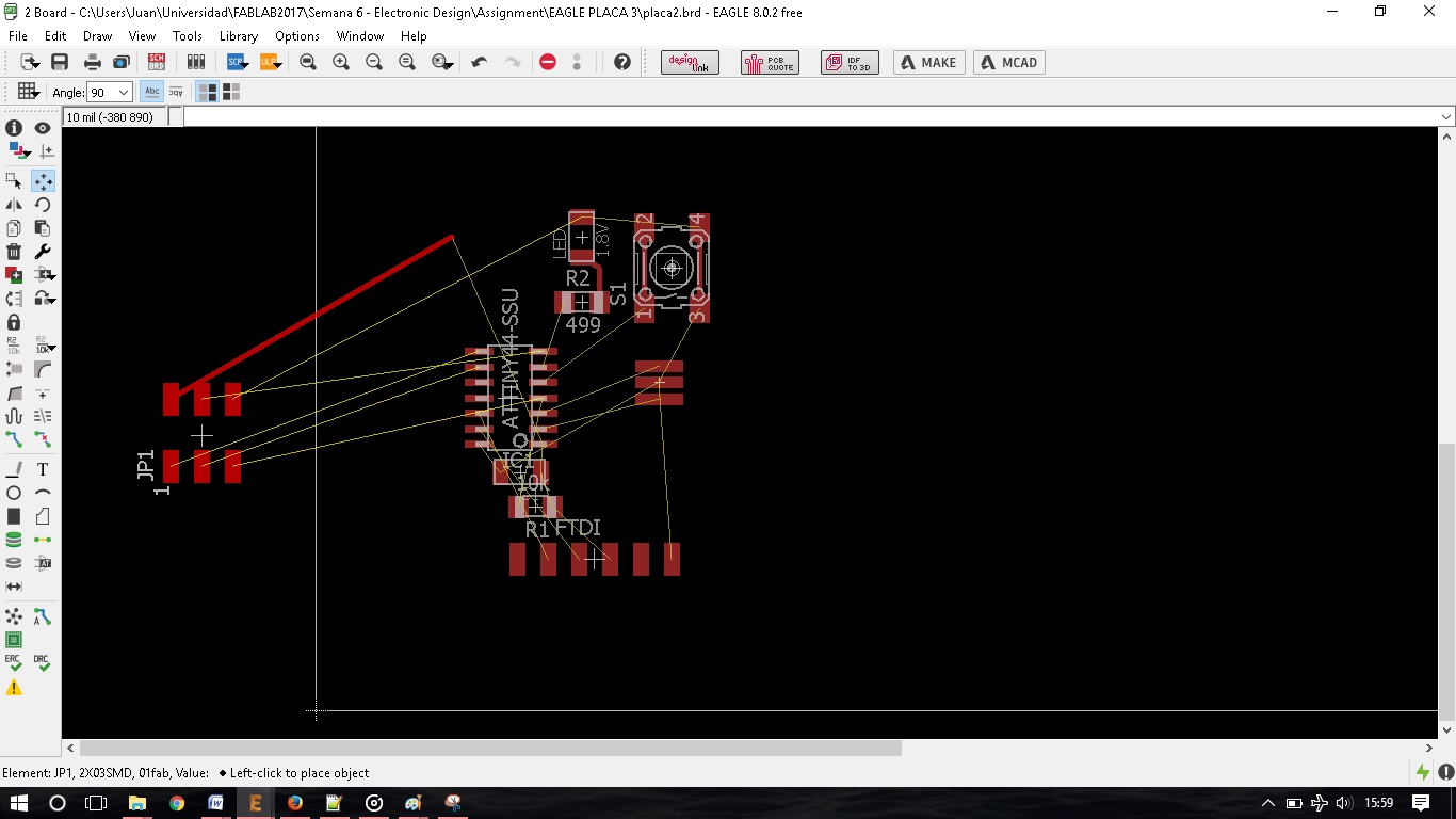
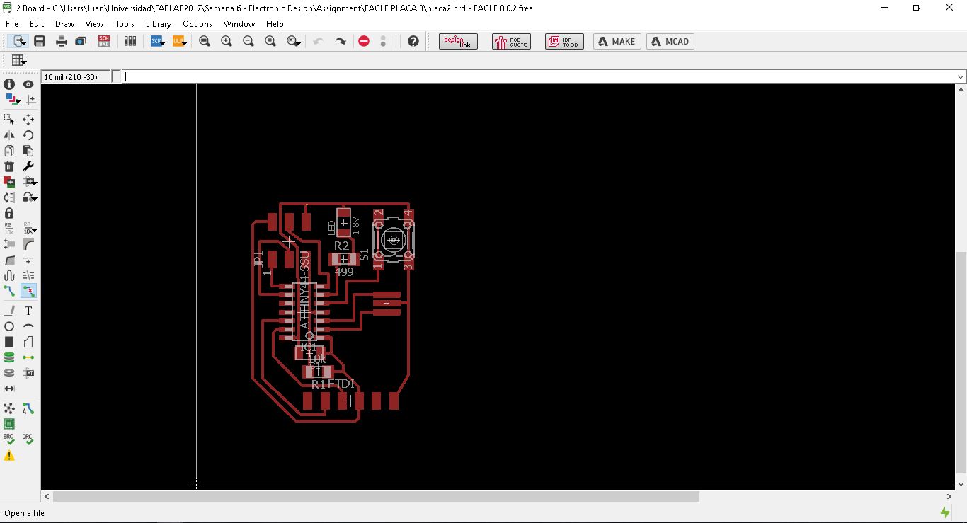
Now I can place the components where they are finally going to be.
Once I knew the idea of where I wanted the components to be in, I started to create the different traces that connect one pin with another.
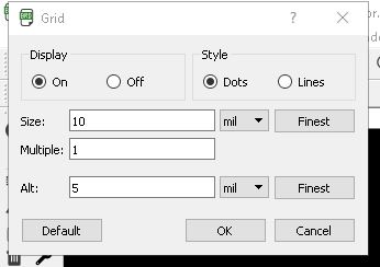
For it to work properly, I activated the grid with having 10 mil size with multiples of 1. On the display option, turn it on so when zooming in, it is easy to calculate.
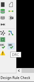
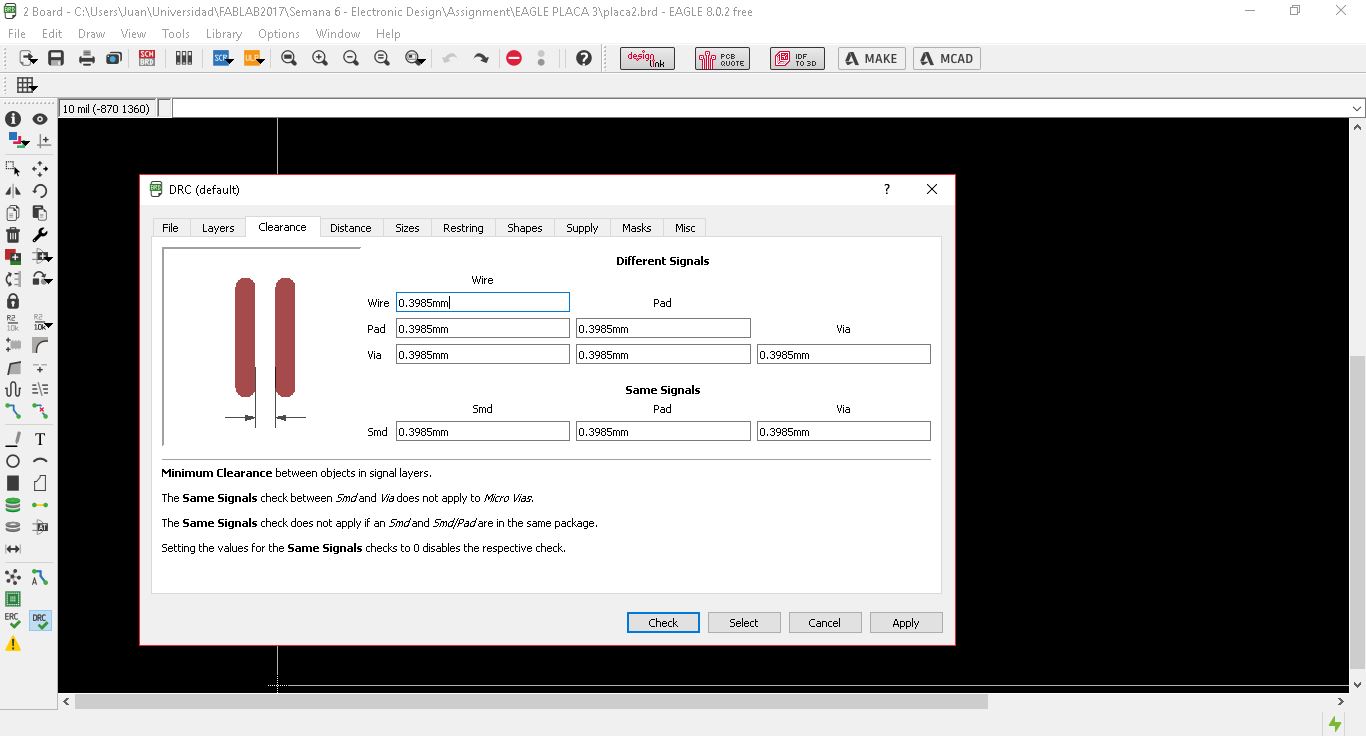
The result: To make sure I have designed properly all the board, I need to check on the toolbar, a button named 'DRC', where it checks all the design rules I previously entered.
These design rules are based on the mill I am using (1/64 mil) for creating the circuit and another mill (1/32) for cutting the board and creating the holes.
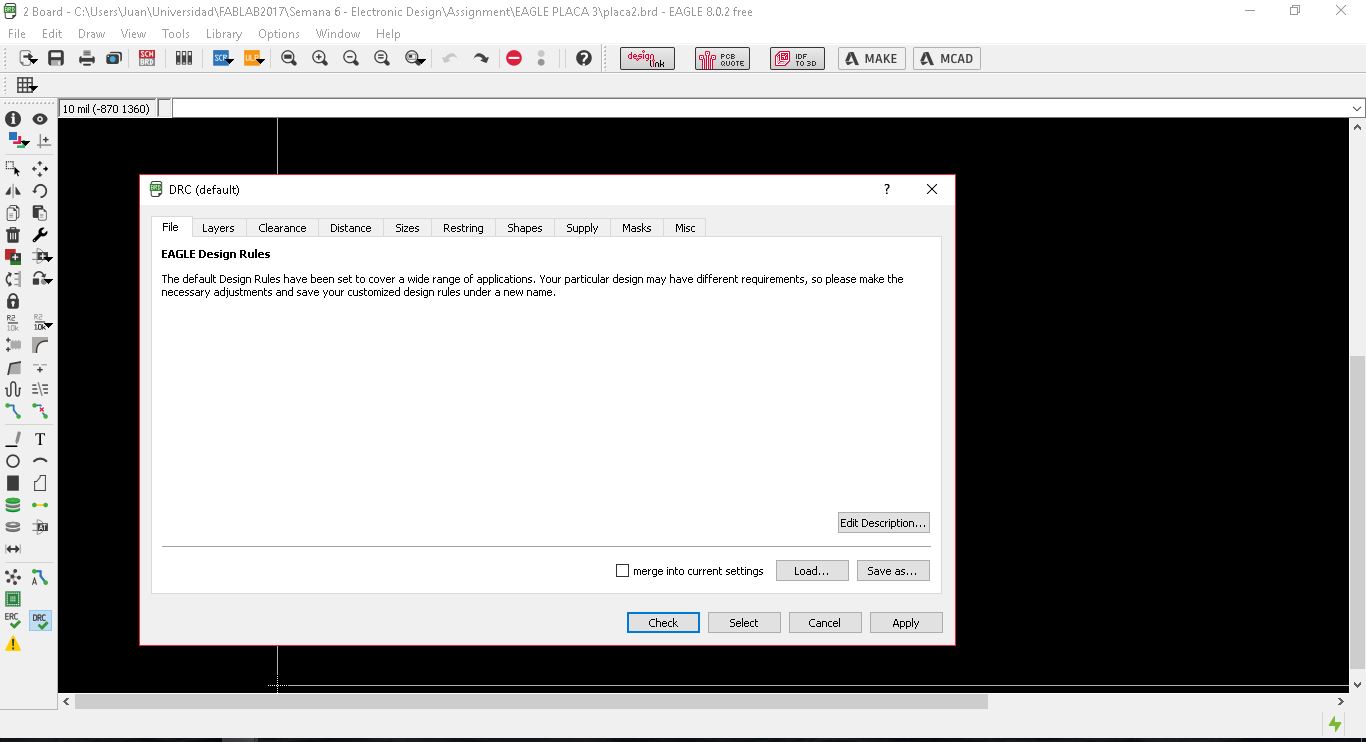
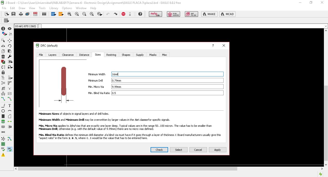
I open the design rules menu and modify what I need:
-'Clearance': change all the dimensions to 1/64 inch mill = 0.3985 mm (I am using mm in this program)
-Sizes: minimum width (16mil), minimum drill (0.79mm).
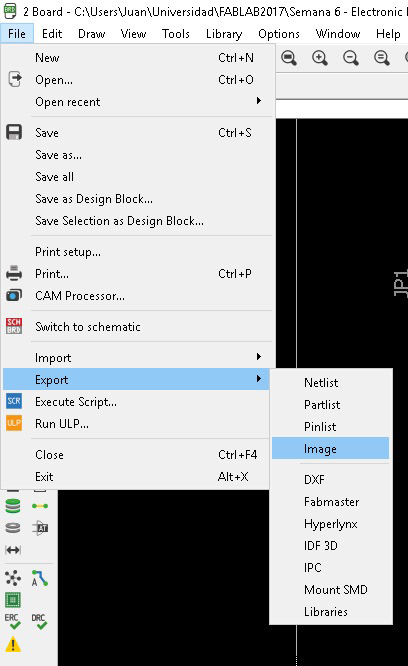
Now press 'Check'. All the different errors stand out. Change, make sure all the rules are followed and now it is time export the image.
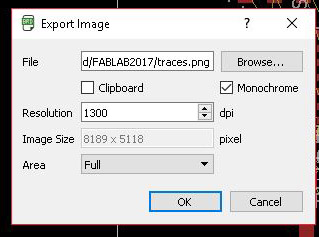
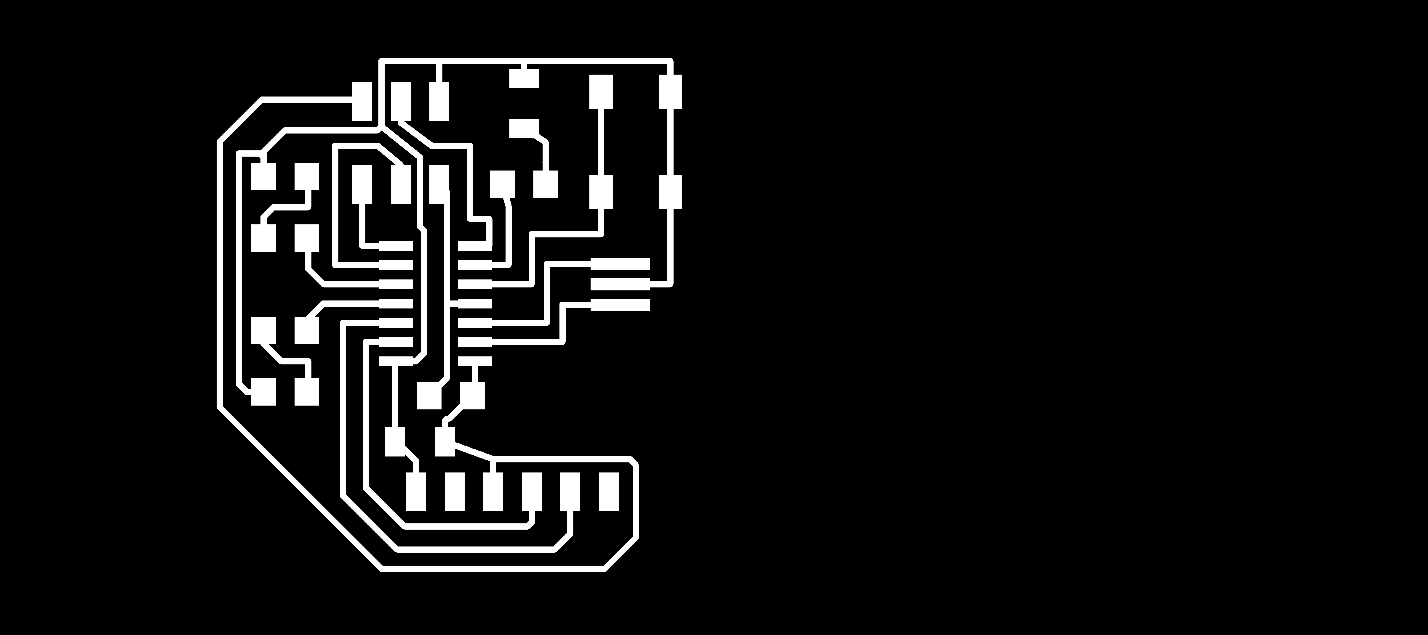
I exported it to a PNG file, monochrome with 1300dpi quality.
The Result:
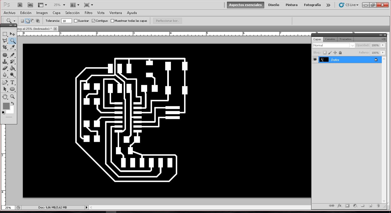
Now I need to open photoshop and erase all the black area that I do not need.
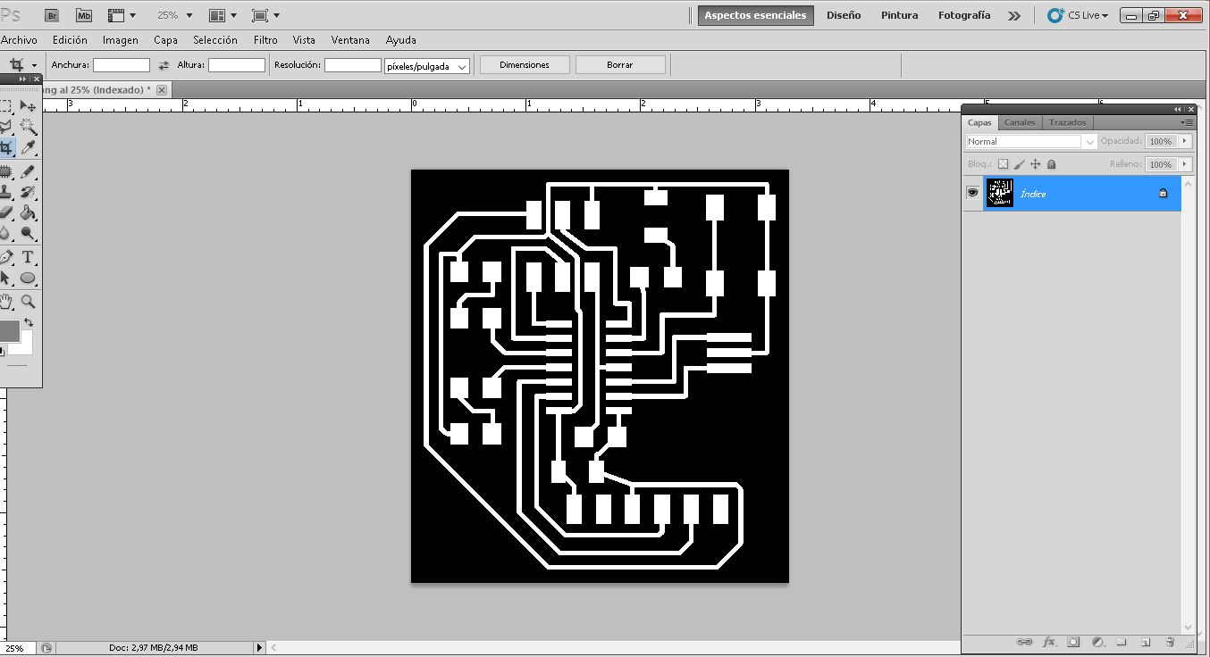
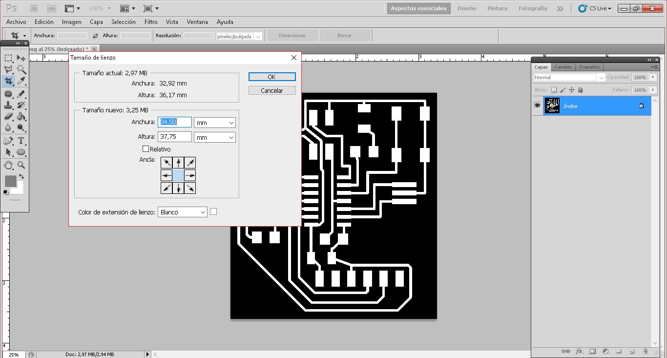
Before sending the png to the modela to mill the board, I need first to create a white frame. This white frame will then turned into black in a new image so mods cuts it with the 1/32 mill.
I open 'Image'-->'Cancas Size'--> and expand the image 0.79mm on each side. In total, that means 1.58mmin width and 1.58mm in height.
The result can be seen on the image below:
Now save image as PNG with the same dpi.
For the cut on the perimeter, the white frame needs to turn black and the rest inside white. All the black area will be milled by the modela, and as it is the 1/32 drilling mill, it will cut it.
Final Result:
Traces for 1/64 mill
Cutting the board from the bed with 1/32 mill:
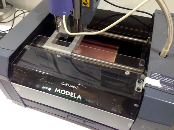
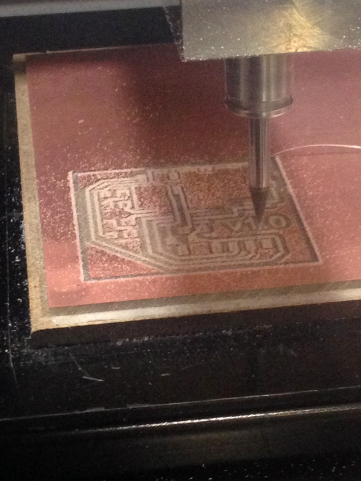
5. Milling the Board
Turn on the Modela MDX-20, open connection with the server with './mods_serial' and upload my .PNG file.
Parameters used:
SET PCB DEFAULTS
activate: 'Mill Traces 1/64'
tool diameter (in): 0.0156
cut depth (in): 0.004
max depth (in): 0.004
offset number: 4
The rest of the parameters leave as they appear when selecting 'Mill Traves 1/64'.
CALCULATE
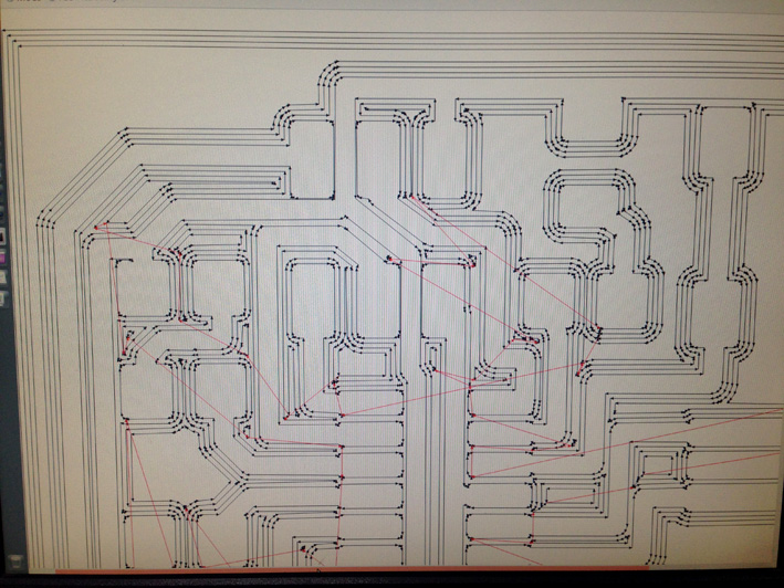
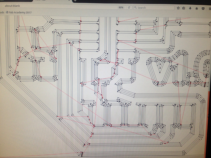
A new window appears with how the machine is going to mill the board. Analyse it completely. In this step,
I had some minor issues as described in '7. Problems Accounted' (botón), as some traces where not going to
be milled correctly.
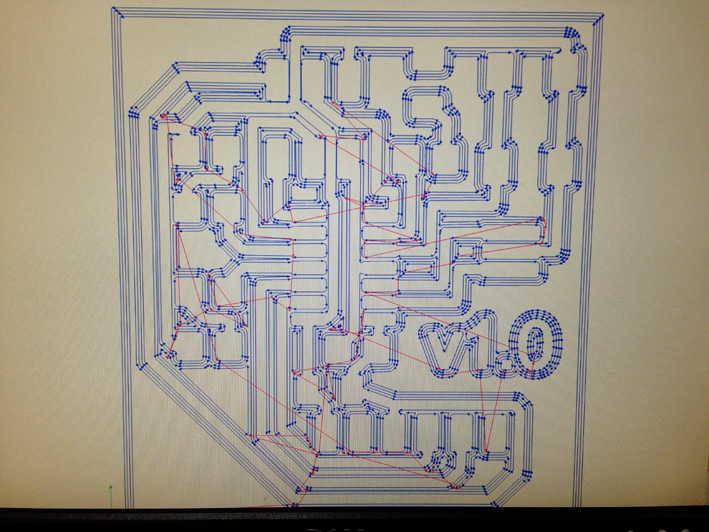
After fixing all those minor problems and checking everything was in the correct place, I selected my origin
to start milling.
This is how the machine is going to mill my board:
ZEROING THE MILL
Using the method learnt on the previous assignment 'Week 4 - Electronic Production', I zeroed this time
correctly and started milling.
SEND
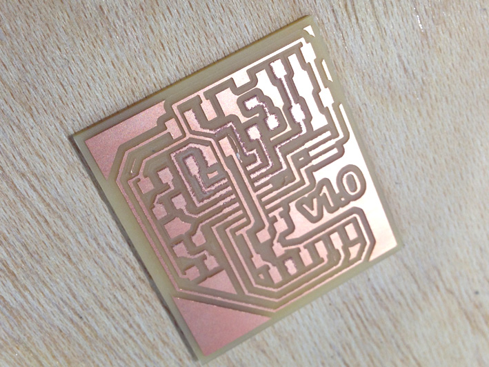
Board Milled
As it can be seen on the picture above, just where the MCU is going to be placed, it has some rough copper
cuts. At first, it is not going to give any problems, but I could have difficulties while soldering
the MCU ATtiny 44.
After discussing it with my instructor the issue, I should not have any problems.
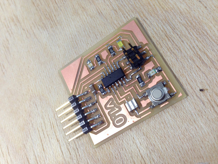
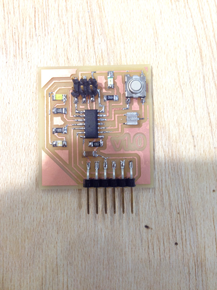
The Board Already Soldered
Unfortunately, I did not have time to take some pictures while I was soldering as it was a friday afternoon, with the lab nearly closing.
Fortunately, after soldering and making sure all the connections were where they are supposed to be, this is the result:
6. Testing the Board
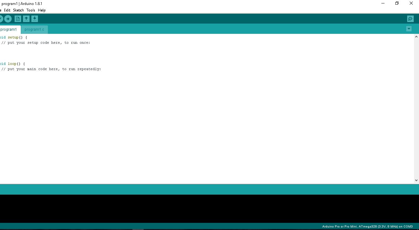
First, I needed to download a program with which I could communicate with my board. Arduino is the one
I am looking for:
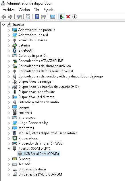
Then, I installed the FTDI Drivers
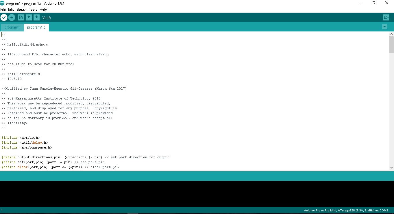
Now, once I have the software needed to test my board, I copied Neil's code example from the fabacademy's assignment,
and paste it inside Arduino.
To finish, I wanted to test the board with the code Neil provided us in the fabacademy website. I opened Arduino and start a new file. Then, open a new window and paste all Neil's code saving it as 'program1.c'.
Once I had everything read, I uploaded the code to the board and test it. Whatever you wrote on the serial monitor, the board answered the same thing back.
Here is Neil's Code that I have used:
			//
//
// hello.ftdi.44.echo.c
//
// 115200 baud FTDI character echo, with flash string
//
// set lfuse to 0x5E for 20 MHz xtal
//
// Neil Gershenfeld
// 12/8/10

//Modified by Juan García-Maestro Gil-Casares (March 6th 2017)
//
// (c) Massachusetts Institute of Technology 2010
// This work may be reproduced, modified, distributed,
// performed, and displayed for any purpose. Copyright is
// retained and must be preserved. The work is provided
// as is; no warranty is provided, and users accept all
// liability.
//

#include <avr/io.h>
#include <util/delay.h>
#include <avr/pgmspace.h>

#define output(directions,pin) (directions |= pin) // set port direction for output
#define set(port,pin) (port |= pin) // set port pin
#define clear(port,pin) (port &= (~pin)) // clear port pin
#define pin_test(pins,pin) (pins & pin) // test for port pin
#define bit_test(byte,bit) (byte & (1 << bit)) // test for bit set
#define bit_delay_time 8.5 // bit delay for 115200 with overhead
#define bit_delay() _delay_us(bit_delay_time) // RS232 bit delay
#define half_bit_delay() _delay_us(bit_delay_time/2) // RS232 half bit delay
#define char_delay() _delay_ms(10) // char delay

#define serial_port PORTA
#define serial_direction DDRA
#define serial_pins PINA
#define serial_pin_in (1 << PA0)
#define serial_pin_out (1 << PA1)

#define max_buffer 25

void get_char(volatile unsigned char *pins, unsigned char pin, char *rxbyte) {
   //
   // read character into rxbyte on pins pin
   //    assumes line driver (inverts bits)
   //
   *rxbyte = 0;
   while (pin_test(*pins,pin))
      //
      // wait for start bit
      //
      ;
   //
   // delay to middle of first data bit
   //
   half_bit_delay();
   bit_delay();
   //
   // unrolled loop to read data bits
   //
   if pin_test(*pins,pin)
      *rxbyte |= (1 << 0);
   else
      *rxbyte |= (0 << 0);
   bit_delay();
   if pin_test(*pins,pin)
      *rxbyte |= (1 << 1);
   else
      *rxbyte |= (0 << 1);
   bit_delay();
   if pin_test(*pins,pin)
      *rxbyte |= (1 << 2);
   else
      *rxbyte |= (0 << 2);
   bit_delay();
   if pin_test(*pins,pin)
      *rxbyte |= (1 << 3);
   else
      *rxbyte |= (0 << 3);
   bit_delay();
   if pin_test(*pins,pin)
      *rxbyte |= (1 << 4);
   else
      *rxbyte |= (0 << 4);
   bit_delay();
   if pin_test(*pins,pin)
      *rxbyte |= (1 << 5);
   else
      *rxbyte |= (0 << 5);
   bit_delay();
   if pin_test(*pins,pin)
      *rxbyte |= (1 << 6);
   else
      *rxbyte |= (0 << 6);
   bit_delay();
   if pin_test(*pins,pin)
      *rxbyte |= (1 << 7);
   else
      *rxbyte |= (0 << 7);
   //
   // wait for stop bit
   //
   bit_delay();
   half_bit_delay();
   }

void put_char(volatile unsigned char *port, unsigned char pin, char txchar) {
   //
   // send character in txchar on port pin
   //    assumes line driver (inverts bits)
   //
   // start bit
   //
   clear(*port,pin);
   bit_delay();
   //
   // unrolled loop to write data bits
   //
   if bit_test(txchar,0)
      set(*port,pin);
   else
      clear(*port,pin);
   bit_delay();
   if bit_test(txchar,1)
      set(*port,pin);
   else
      clear(*port,pin);
   bit_delay();
   if bit_test(txchar,2)
      set(*port,pin);
   else
      clear(*port,pin);
   bit_delay();
   if bit_test(txchar,3)
      set(*port,pin);
   else
      clear(*port,pin);
   bit_delay();
   if bit_test(txchar,4)
      set(*port,pin);
   else
      clear(*port,pin);
   bit_delay();
   if bit_test(txchar,5)
      set(*port,pin);
   else
      clear(*port,pin);
   bit_delay();
   if bit_test(txchar,6)
      set(*port,pin);
   else
      clear(*port,pin);
   bit_delay();
   if bit_test(txchar,7)
      set(*port,pin);
   else
      clear(*port,pin);
   bit_delay();
   //
   // stop bit
   //
   set(*port,pin);
   bit_delay();
   //
   // char delay
   //
   bit_delay();
   }

void put_string(volatile unsigned char *port, unsigned char pin, char *str) {
   //
   // print a null-terminated string
   //
   static int index;
   index = 0;
   do {
      put_char(port, pin, str[index]);
      ++index;
      } while (str[index] != 0);
   }

int main(void) {
   //
   // main
   //
   static char chr;
   static char buffer[max_buffer] = {0};
   static int index;
   //
   // set clock divider to /1
   //
   CLKPR = (1 << CLKPCE);
   CLKPR = (0 << CLKPS3) | (0 << CLKPS2) | (0 << CLKPS1) | (0 << CLKPS0);
   //
   // initialize output pins
   //
   set(serial_port, serial_pin_out);
   output(serial_direction, serial_pin_out);
   //
   // main loop
   //
   index = 0;
   while (1) {
      get_char(&serial_pins, serial_pin_in, &chr);
      put_string(&serial_port, serial_pin_out, "hello.ftdi.44.echo.c: you typed \"");
      buffer[index++] = chr;
      if (index == (max_buffer-1))
         index = 0;
      put_string(&serial_port, serial_pin_out, buffer);
      put_char(&serial_port, serial_pin_out, '\"');
      put_char(&serial_port, serial_pin_out, 10); // new line
      }
   }
7. Problems Accounted
After the electronic production week, where I broke the first board, this week's assignment I was more careful
while doing everything. One big problem that I had during the whole process was using mods.
After mods calculates all the traces that it is going to mill, I had some issues as some independent traces
where combined as they were designed without enough space between them. I had to go back, re-design the board
and check it on mods twice.
Once everything is ok, I started milling without any problems.