Procedure:
0. Assignment
1. Buy all the different components to build my first FabISP board.
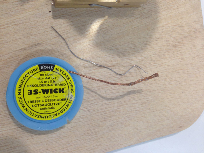
2. Practice with broken components from the lab.
3. Milling the board.https:
4. Stuffing the board.
5. Hero Shot - the board.
6. Connection test.
7. Programming the board.
8. Understand how the board works
here
0. Assignment
group assignment
characterize the specifications of your PCB production process
individual assignment
Make an in-circuit programmer by milling the PCB (program it, so that you can use it to program your
board in Electronics Design week, and in other weeks)
Optionally, trying other processes.
LEARNING OUTCOMES
Describe the process of milling, stuffing, de-bugging and programming
Demonstrate correct workflows and identify areas for improvement if required
HAVE YOU...
...shown how you made and programmed the board
...explained any problems and how you fixed them
..included a ‘hero shot’ of your board
BUYING THE DIFFERENT COMPONENTS:
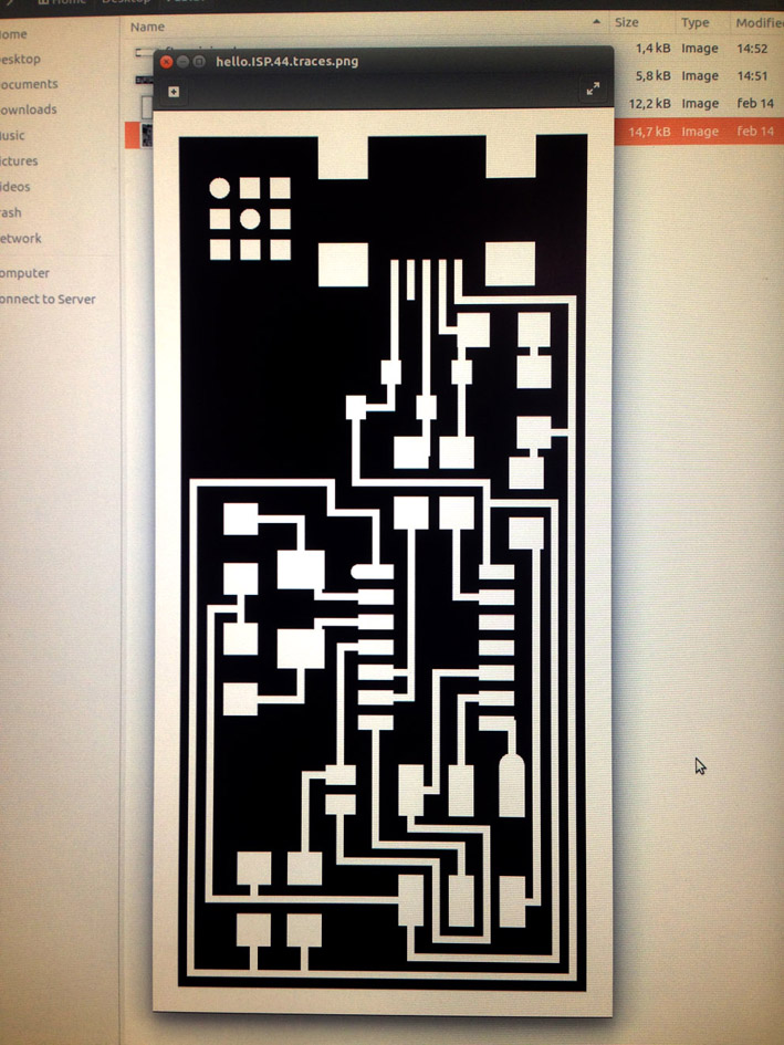
Once I decided to build FabISP hello.ISP.44.cad board, I had a look to all the components I needed:
-1 ATTiny 44 microcontroller
-1 Capacitor 1uF
-2 Capacitor 10 pF
-2 Resistor 100 ohm
-1 Resistor 499 ohm
-1 Resistor 1K ohm
-1 Resistor 10K
-One 6 pin header
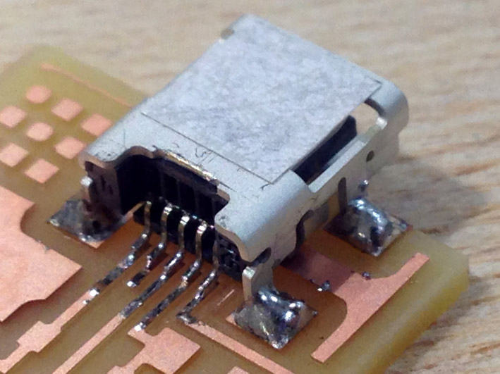
-1 USB connector
-2 jumpers - 0 ohm resistors
-1 Crystal 20MHz
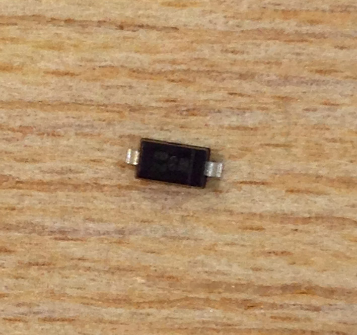
-2 Zener Diode 3.3V
-1 Usb Mini Cable
-1 Ribbon Cable
-Two 6 pin connectors
Then, I had a look to this tutorial to study the way it needed to be built:
Let's get started!
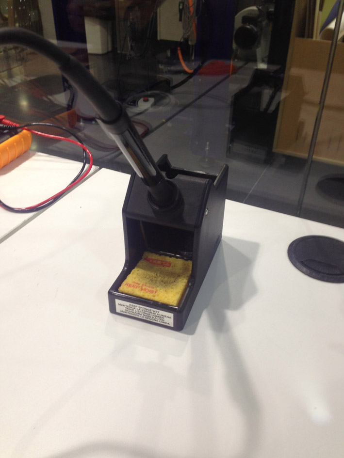
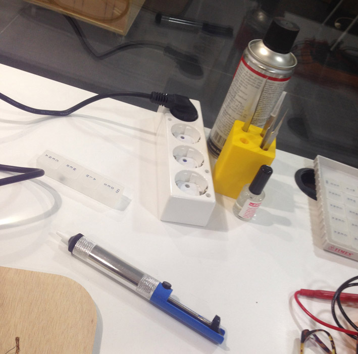
PRACTICING WITH BROKEN COMPONENTS AND GETTING USED TO THE NEW TOOLS
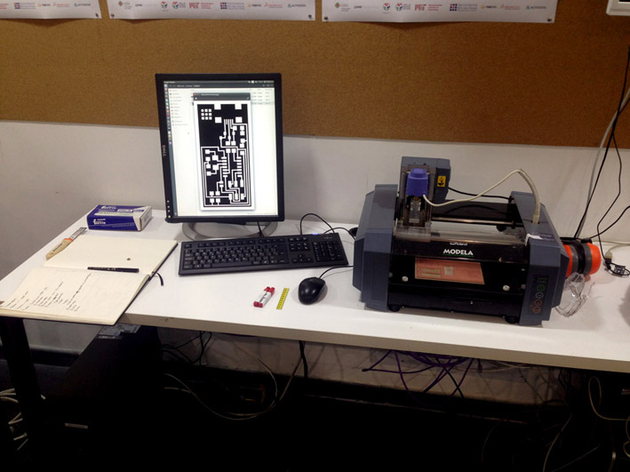
MY WORKSPACE: PRACTICING WITH THE MILLING MACHINE MDX-20 + placing broken endmills to the
machine to practice.
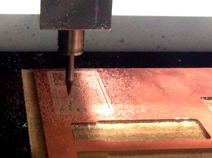
LETS GET STARTED: MILLING MY FIRST BOARD!!
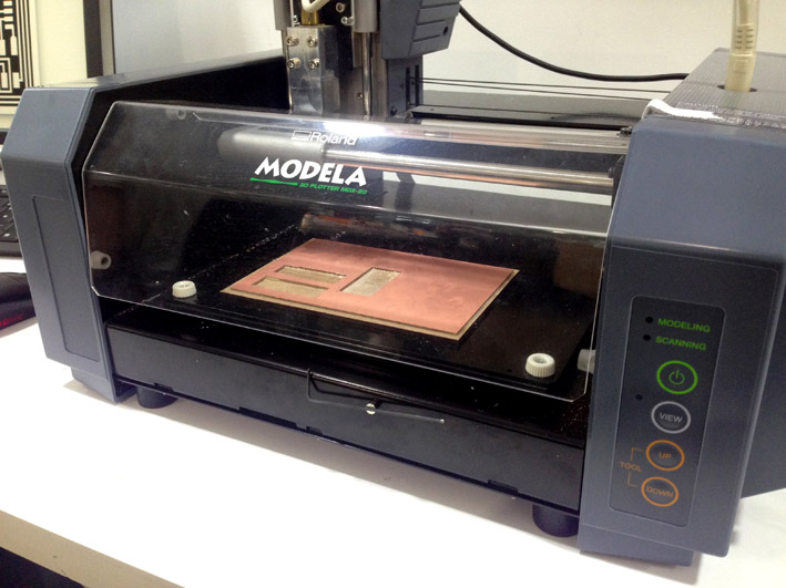
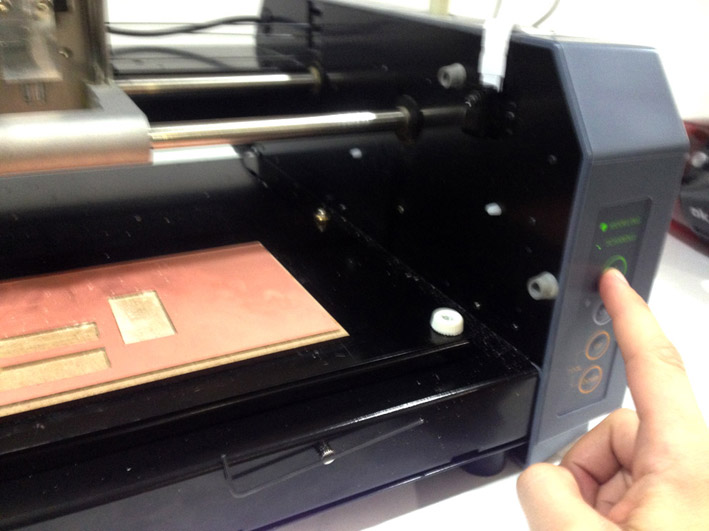
First: Turn on the milling machine
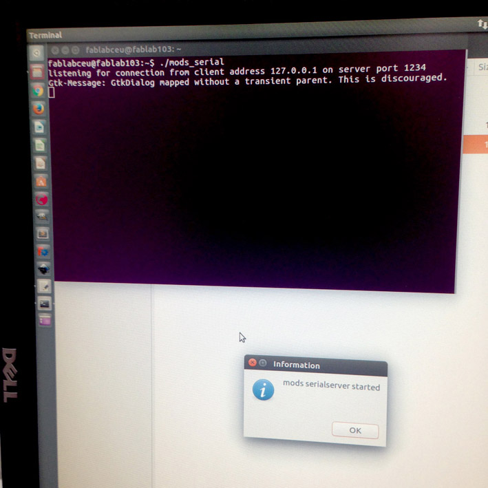
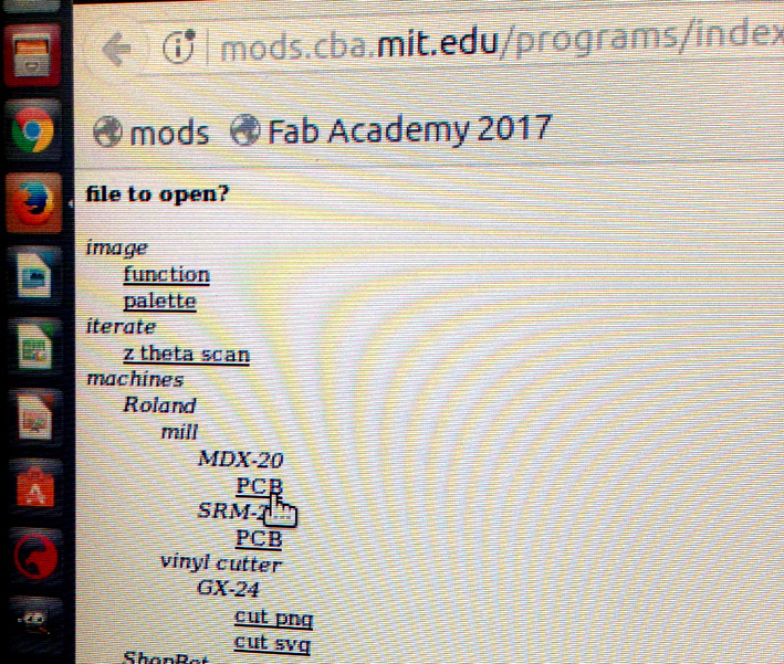
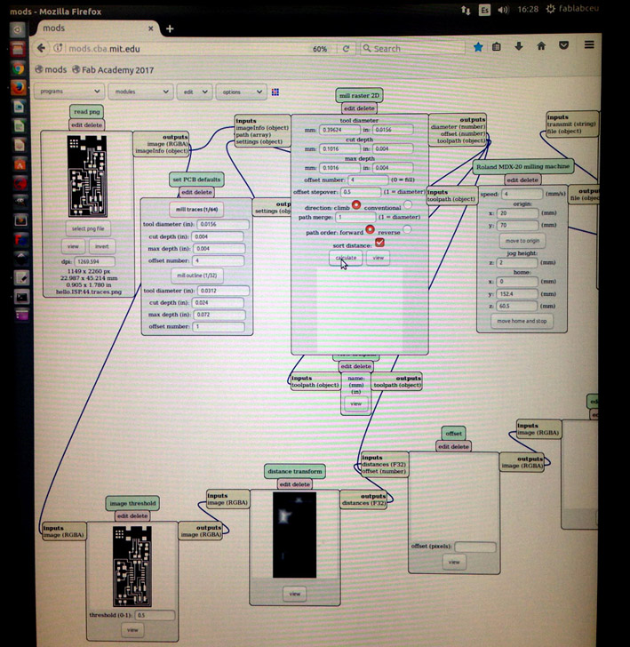
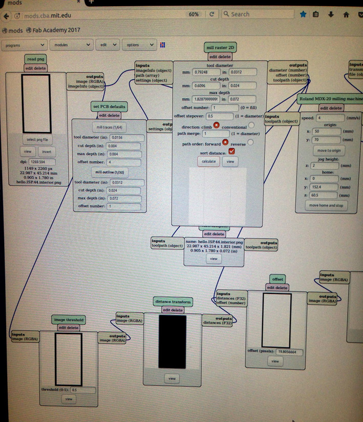
Activating mods on a new terminal
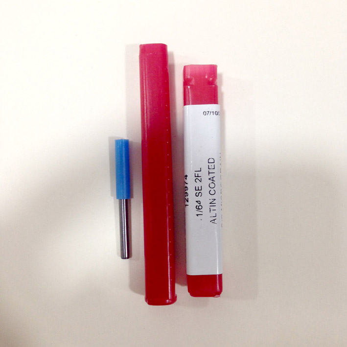
Entering mods mit website + choosing the correct machine + carefully, take the endmill 1/64 and placing it correctly.
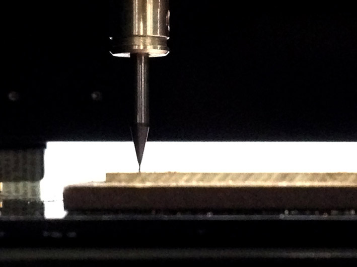
Zeroing correctly the 1/64 endmill.
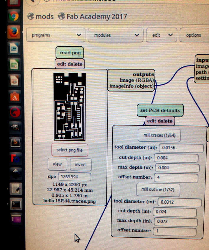
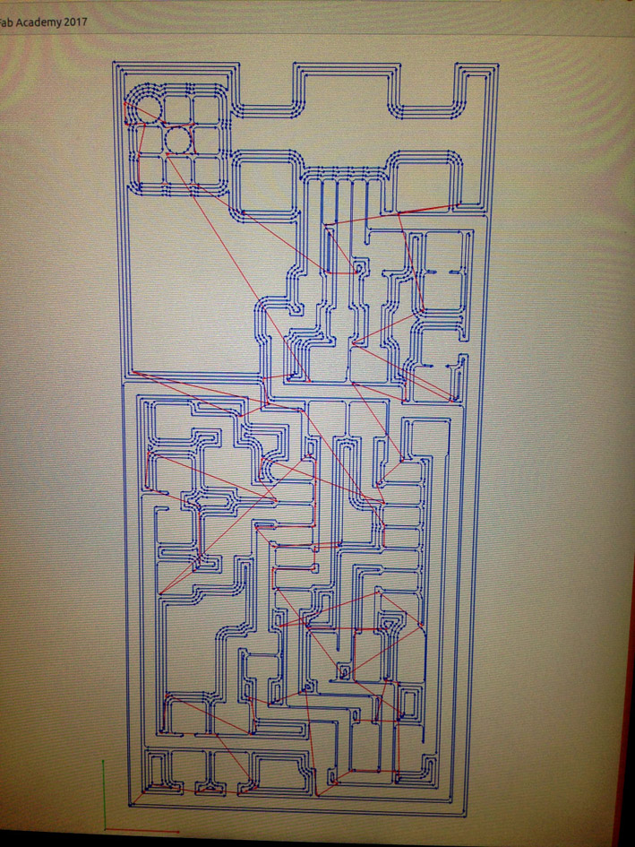
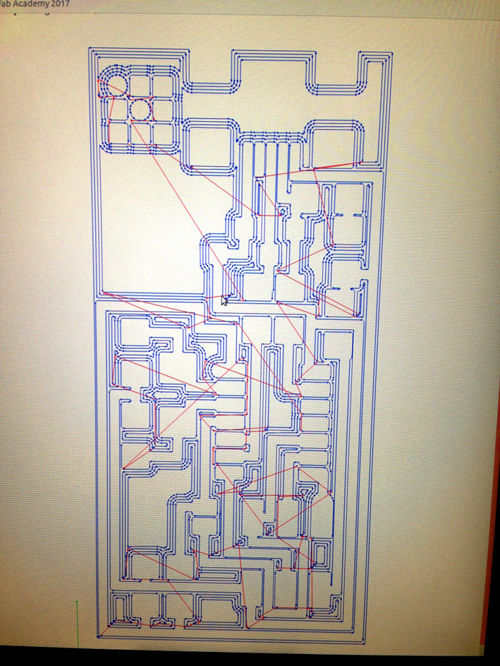
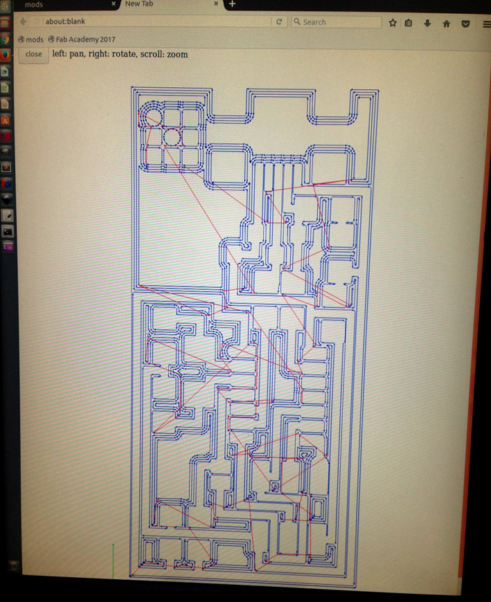
Choosing my hello.ISP.44 png file + choosing 1/64 adjustments.
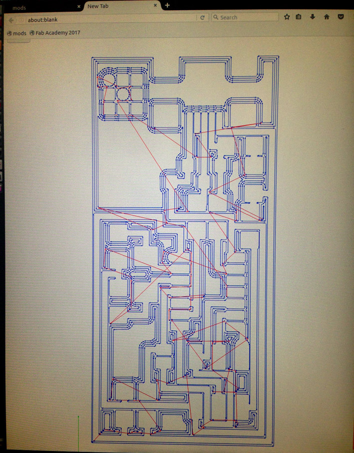
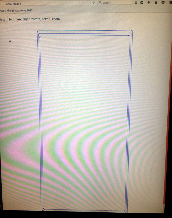
Checking the way the board is going to be milled.
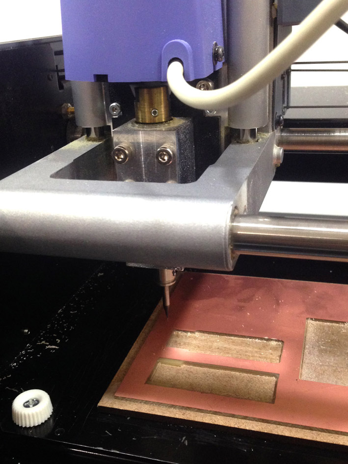
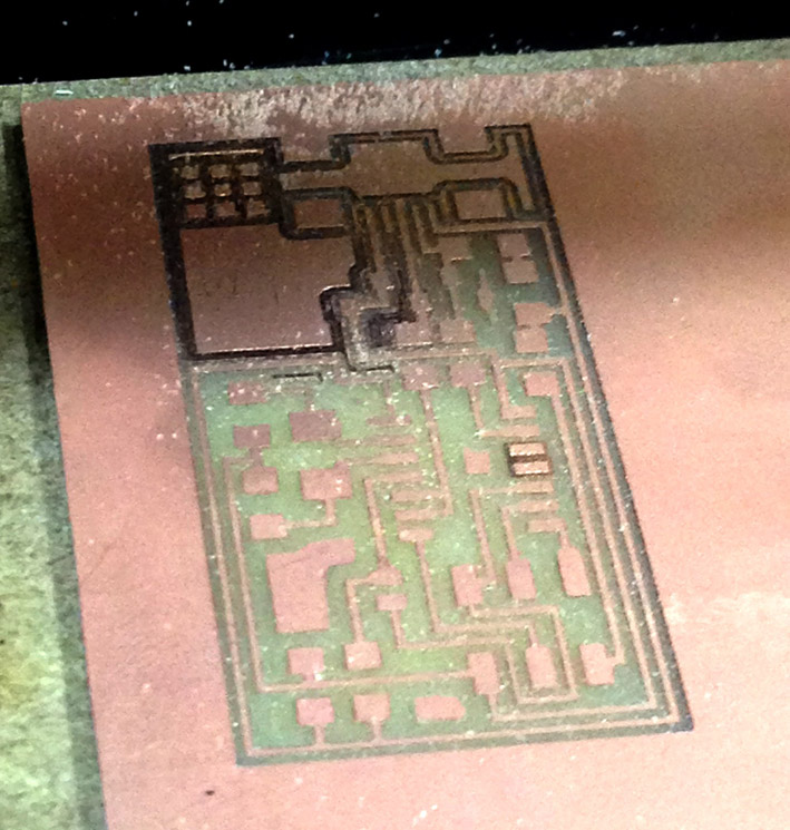
Starting to mill (1st try):
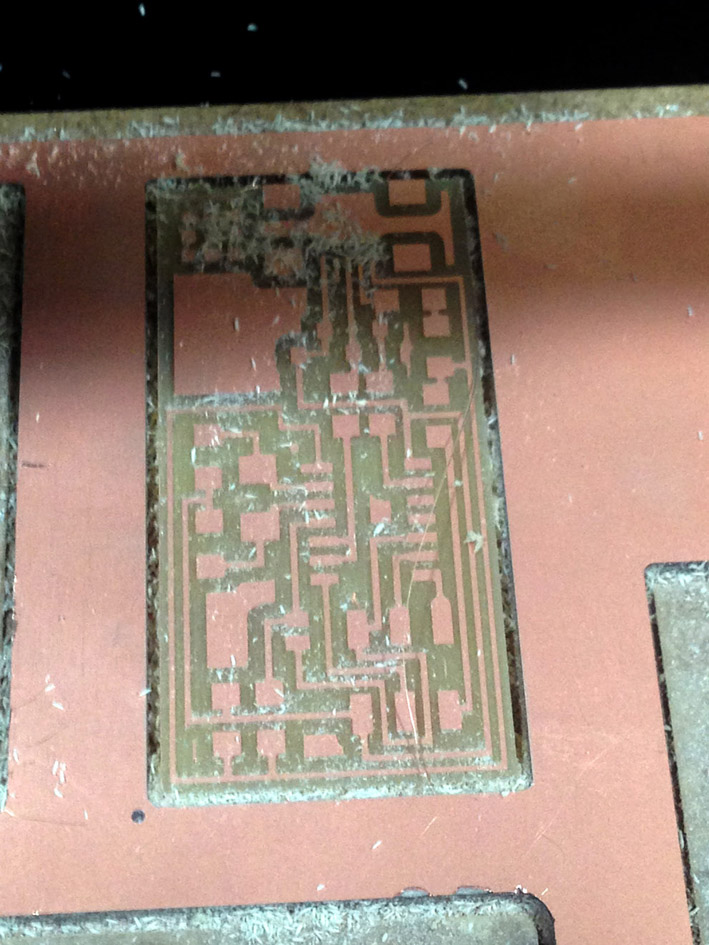
First problem: As it is my first try, I am not sure whether I have zeroed incorrectly or if the
board is slightly elevated from its adhesive tape as only a part of the board has not been milled
correctly. To make sure, I decided to mill a second time just in case something went wrong.
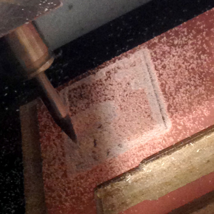
Checking again!
2nd mill done, same result. As nothing really changed, I decided to do the zero again.
What went wrong was probably zeroing the endmill incorrectly in the first place.
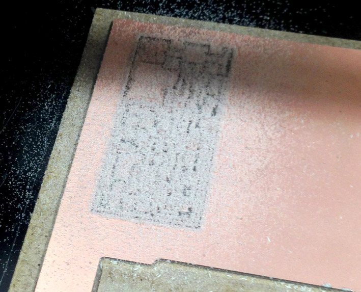
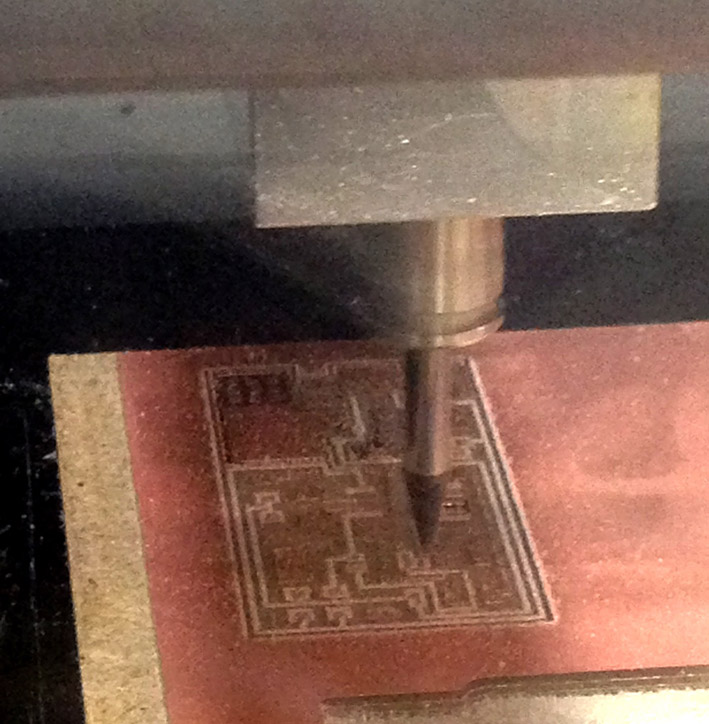
Getting ready to mill again!
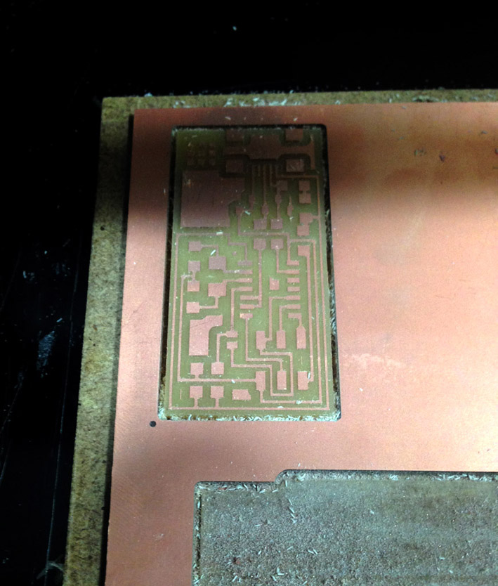
First results! It is working!
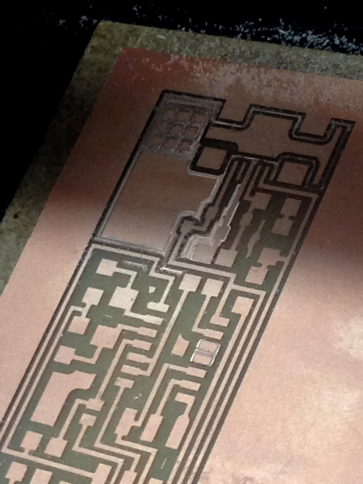
Final result: the board is completely milled. Next step, changing the endmill 1/64 for a 1/32 endmill + adjustments needed in mods.
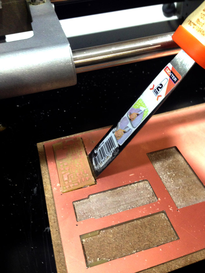
Getting ready for removing it from the sacrificial layer.
Problem! While removing the board, I broke it... I had to repeat the process again.
So, checking everything again to get ready to mill for the 4th time.
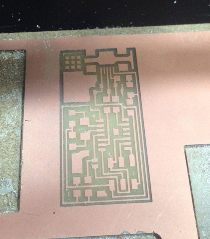
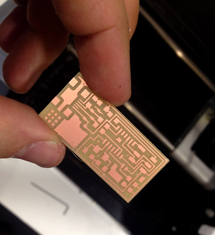
Nice, clean board milled + cut.
I got it! Nice clean new board milled and removed correctly.
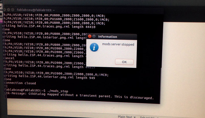
Stopping mods server.
Soldering
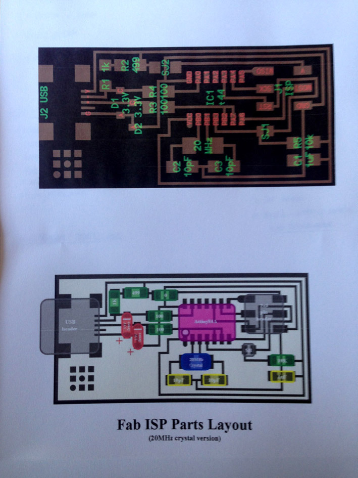
Printing the FabISP labelled board to see where to place the components.
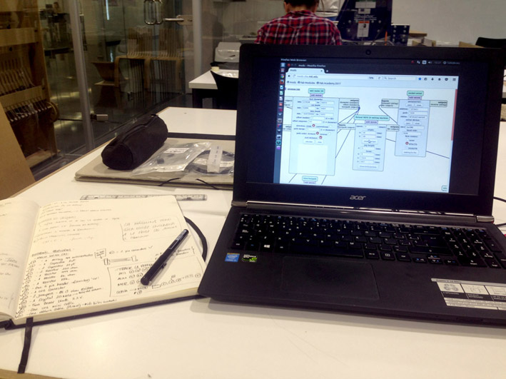
My workspcace
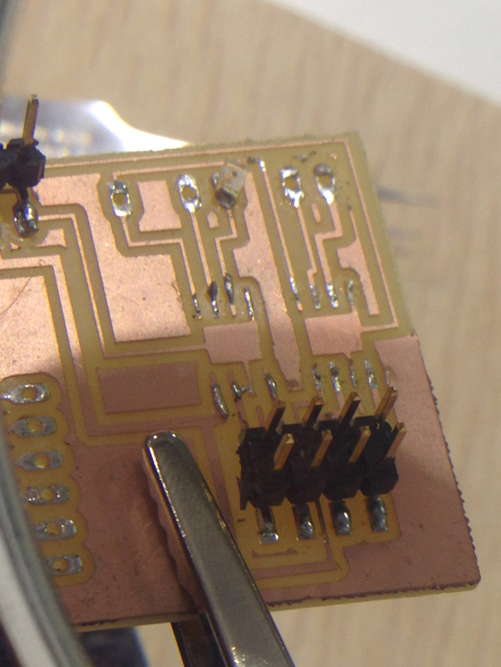
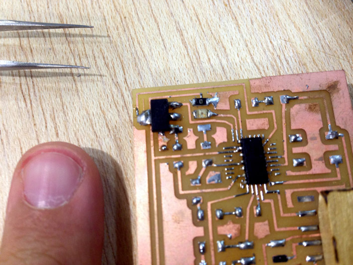
First: soldering the USB header.
Second: the microcontroller.
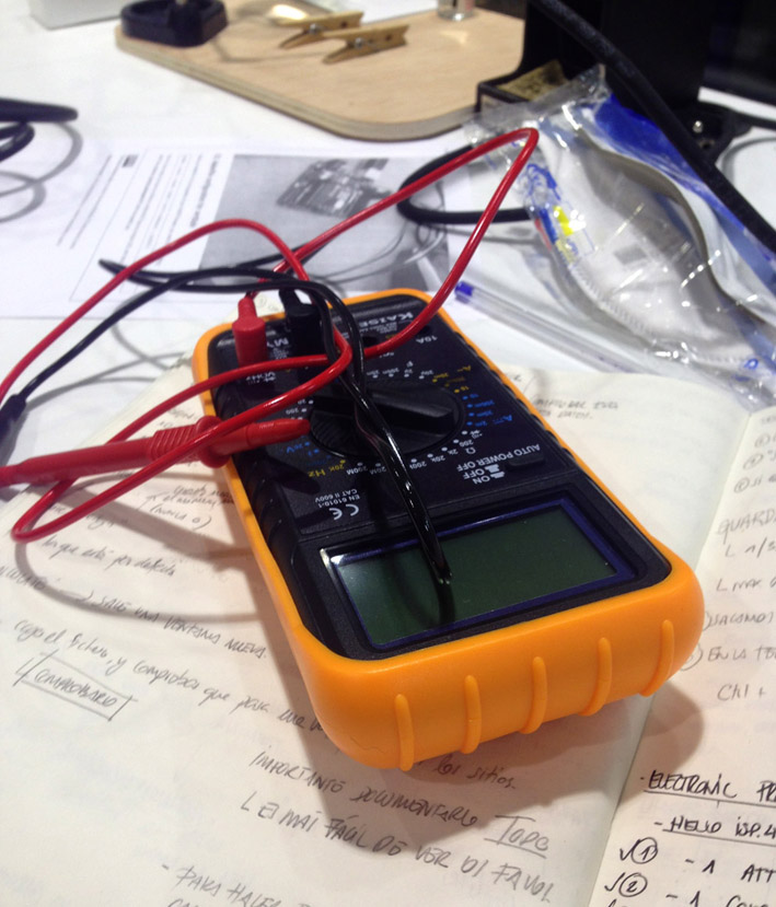
In order to make sure everything is soldered correctly, I checked on the continuity of each
circuit to make sure it works. I repeated this process for each component, except for the last
steps as I was running out of time.
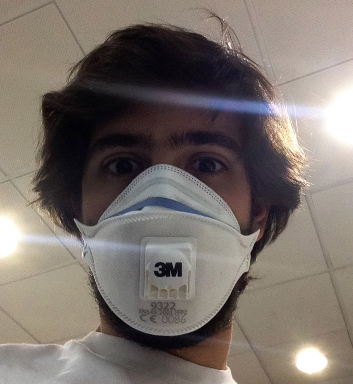
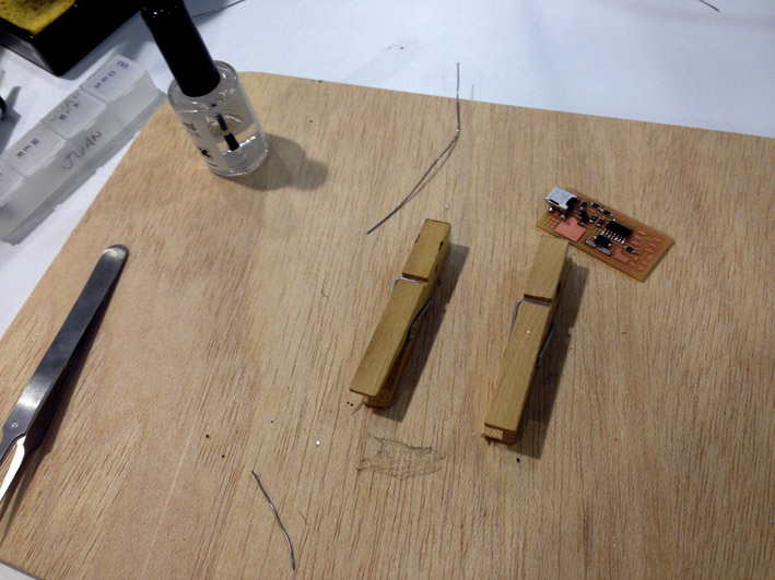
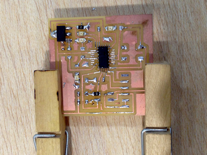
This is me! I started coughing while soldering.
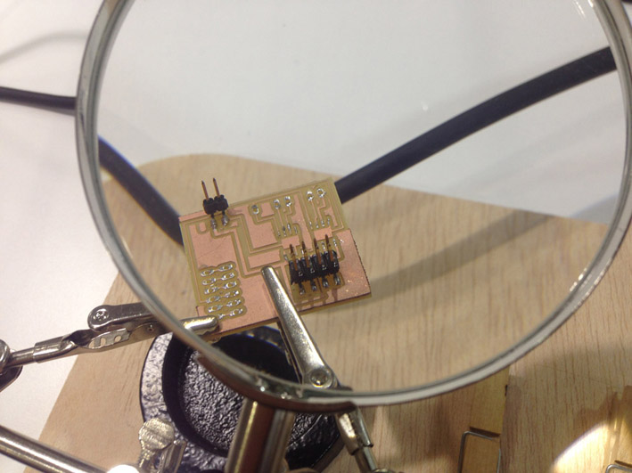
Here is the board partially soldered and my workspace:
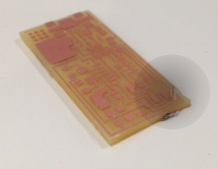
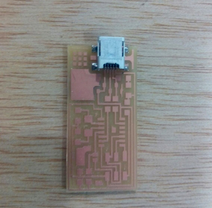
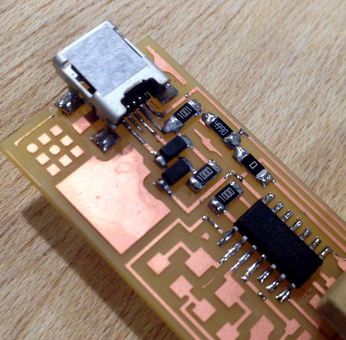
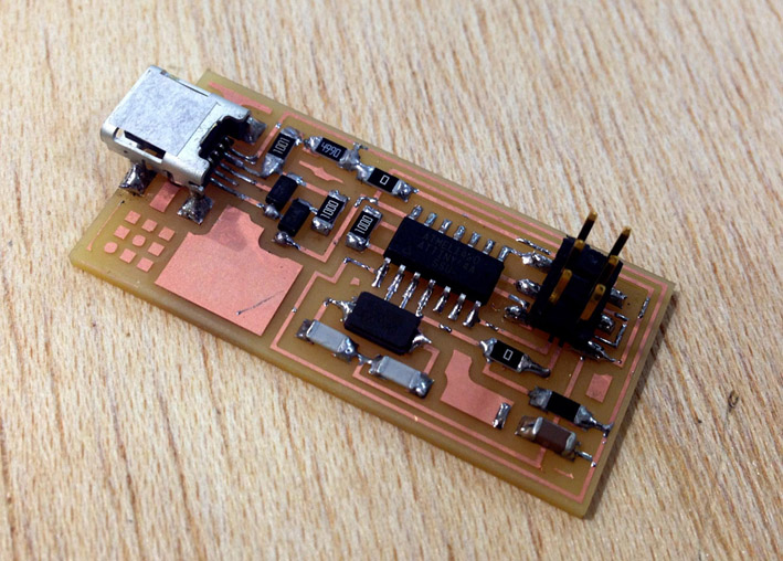
Final Result - Hero Shot of my Board
Final result:
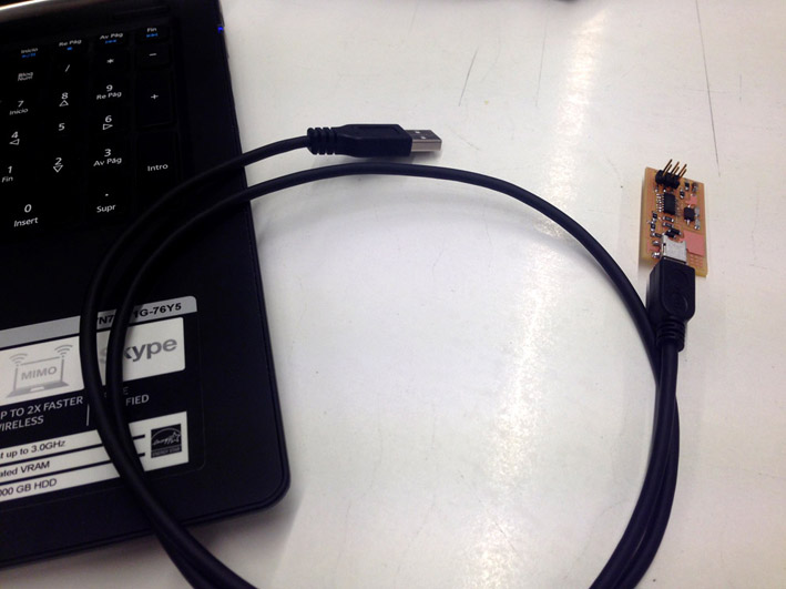
Connection Test
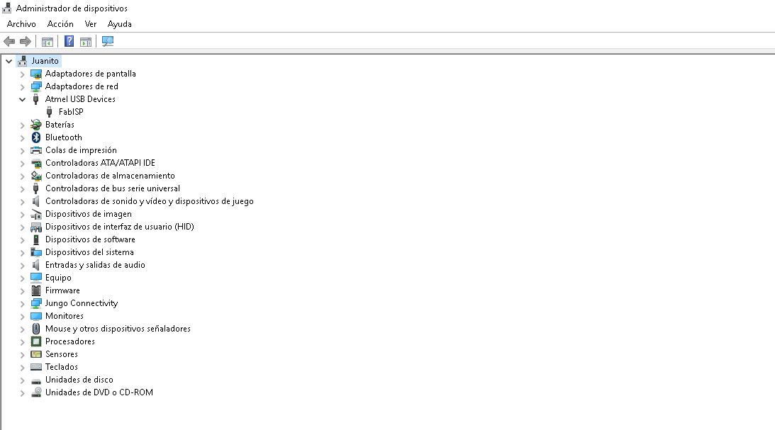
First connection: completed. The computer does not shut down the usb port as my new device draws
the correct amount of energy + Starting to program the programmer!
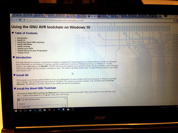
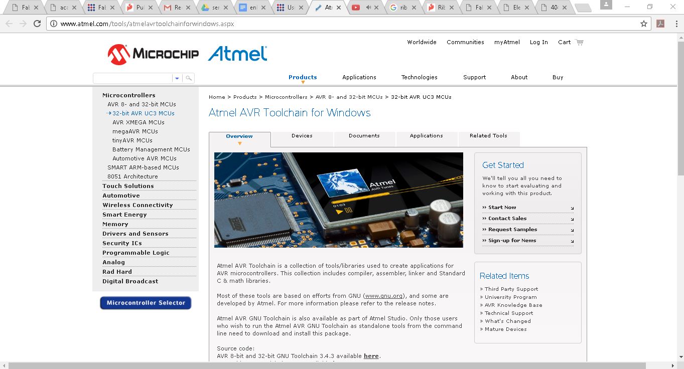
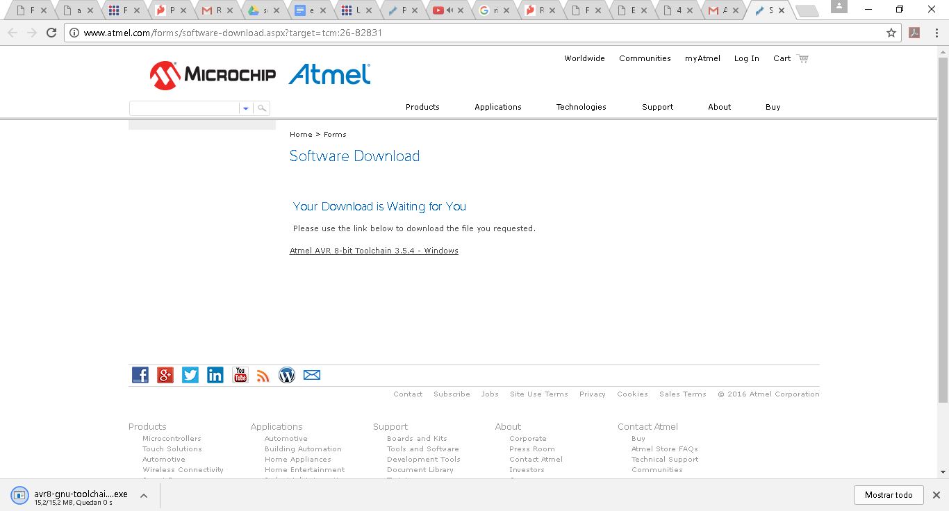
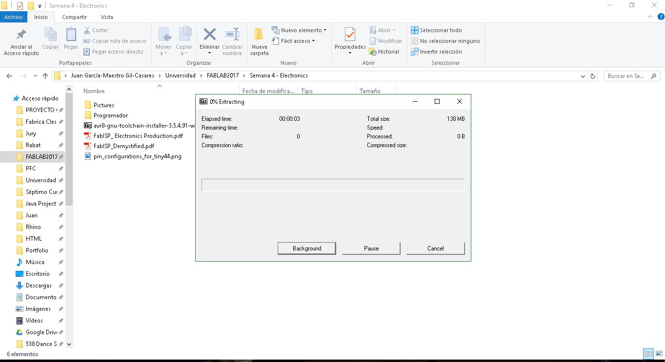
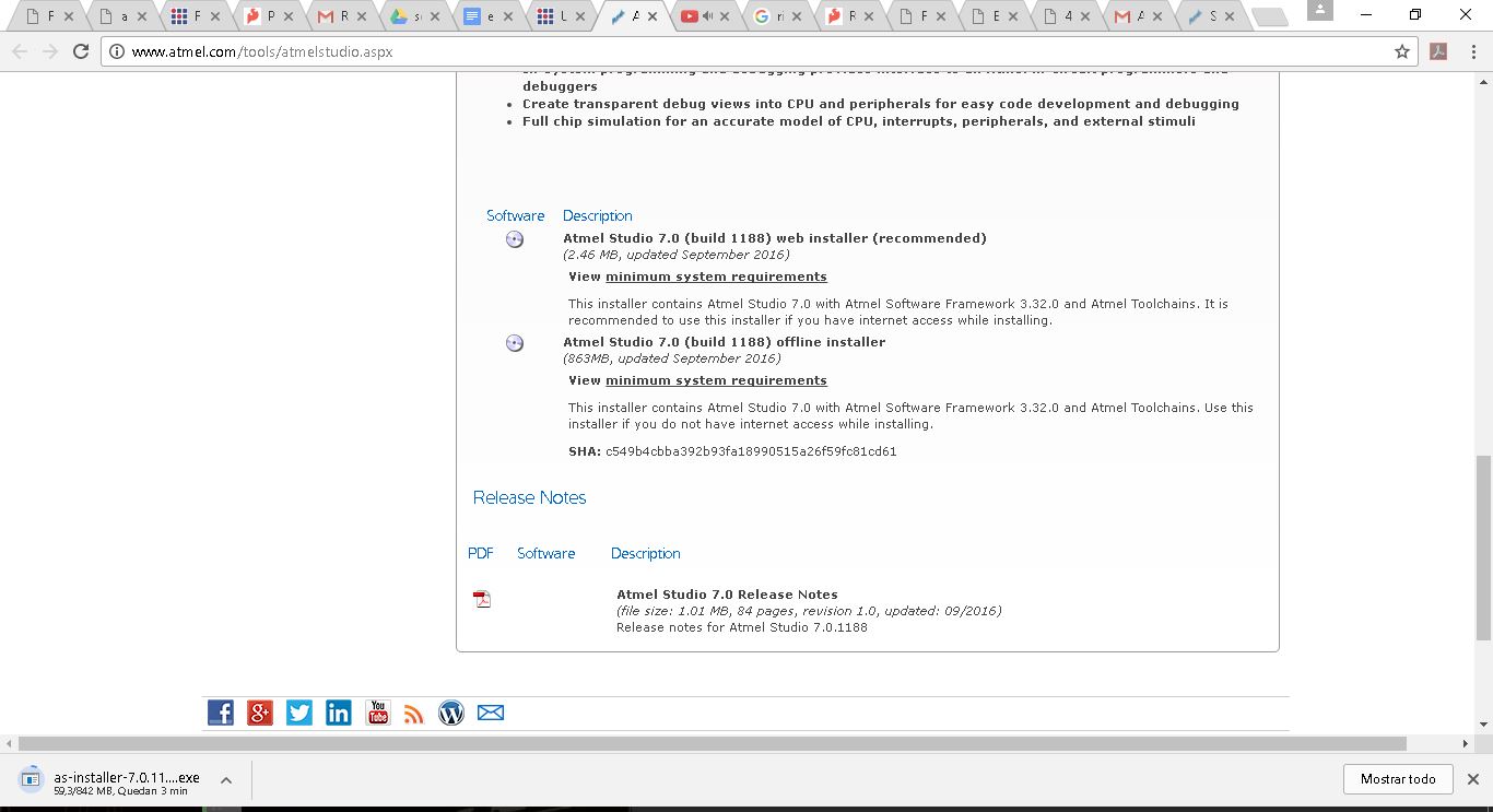
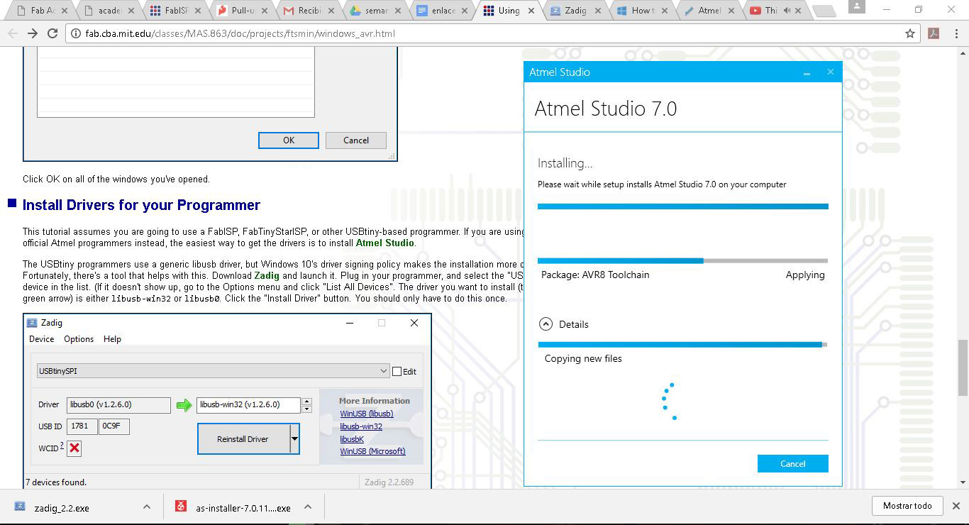
Installing Atmel GNU Toolchain, GNU Make, avrdude and Atmel Studio 7:
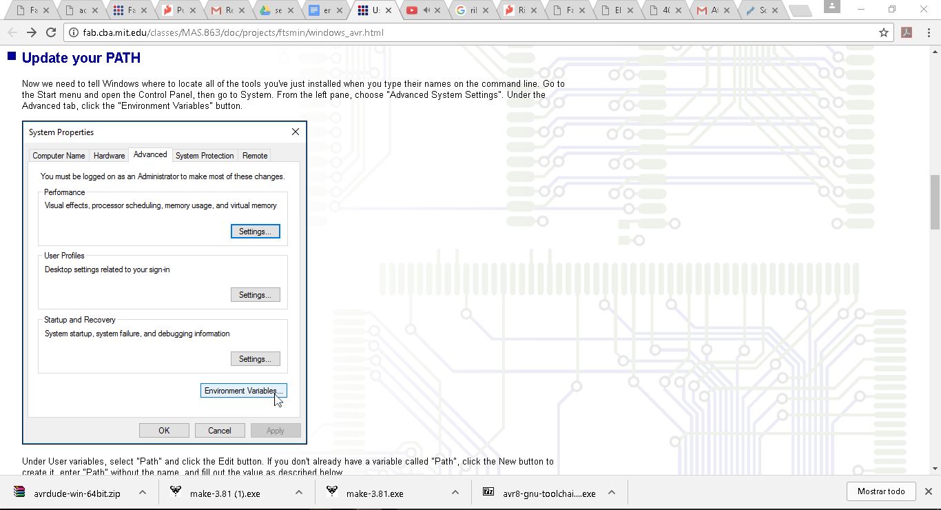
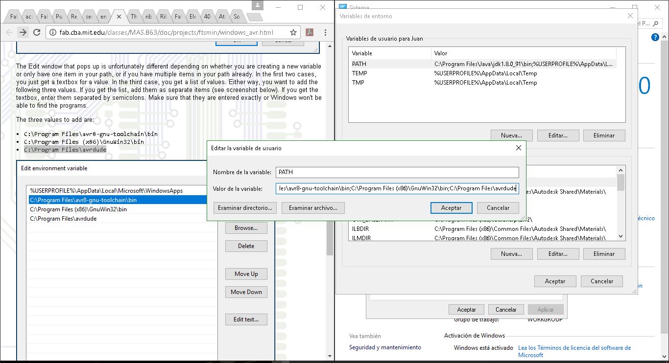
Updating my PATH in computer advanced settings:
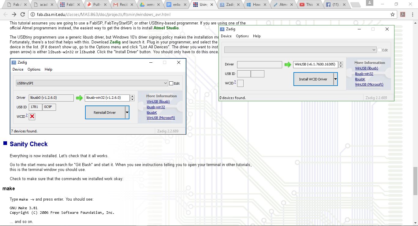
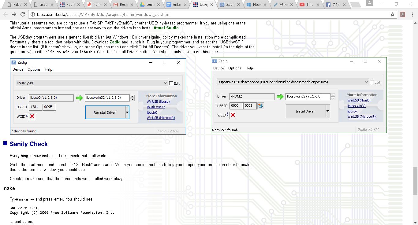
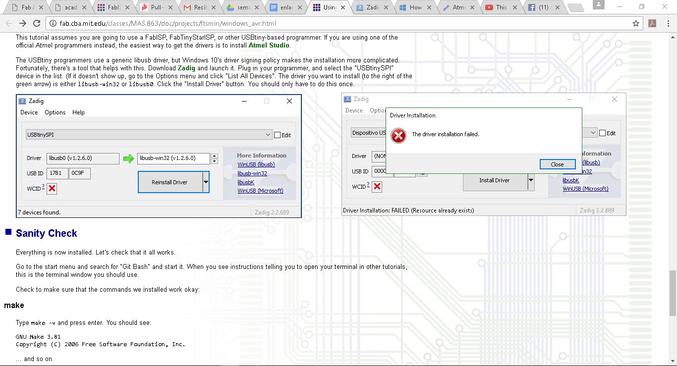
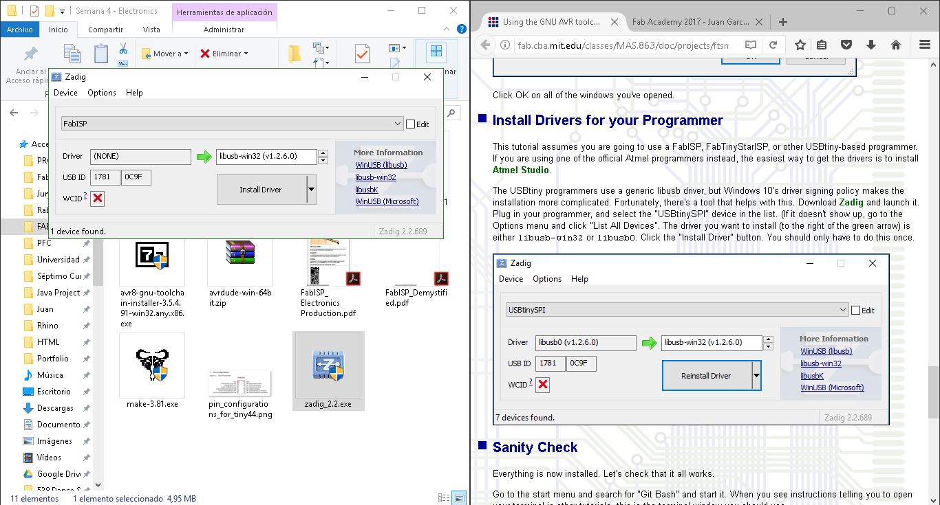
Installing drivers to my programmer:
Final result: fail. I need to check what went wrong.
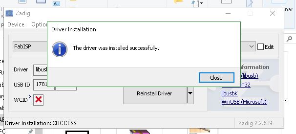
What I did not know until this moment is that I needed a programmer to program my programmer. Once I knew that, the process
was fast: in 10 minutes I had everything done.
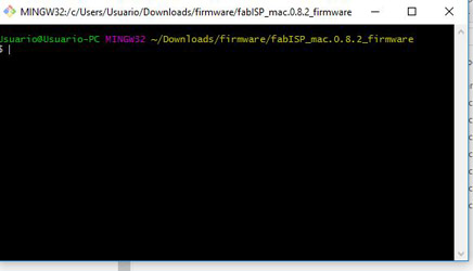
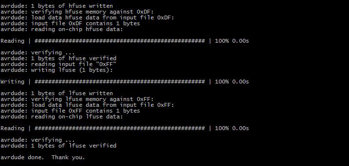
Programming the FabISP:
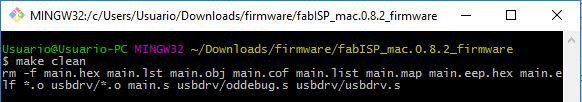
Make Clean command:
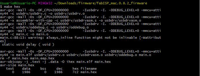
'make hex' command:
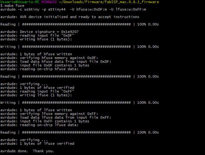
'make fuse' command:
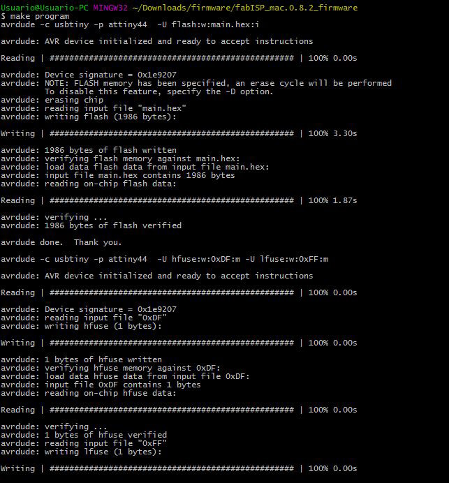
'make program command:
DONE!!!!
My New Programmer!
Understanding how the board works
A 'Printed Circuit Board' (PCB) is the mechanical support that electrically connects electronic components
using conductive tracks made out of laminated copper. These boards can be single sided (the ones
we are using/creating in the fabacademy program), double sided or multi-layer.
The way it is produced in the fablab is by using a milling machine (in my case, the modela MDX-20),
which uses 1/68 mill and 1/32 mills for creating the PCB design board. Once is already milled, now the
components need to be soldered to the board by using conductive metal. The components can vary, but the
most important ones are:
-Resistors
-Capacitors
-Resonators (Crystals)
-Inductors
-Diodes
-Zener Diode
-Transistors
-Mosfet Transistors
-Batteries
-Regulators
-Operational Amplifiers
-Microcontrollers (MCU)
-Sensors
-Actuators
Once all the components are soldered on to the board, one must confirm everything is well connected on to the other.
Then, it will be ready to be programmed.