Introduction
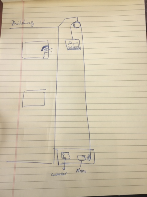
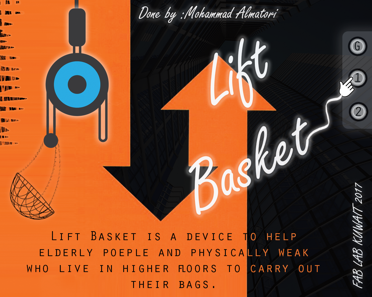
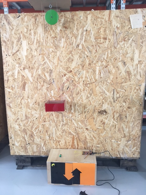
The Idea of the project is to develop a device that helps peolpe carry their bags to higher floors. Elderly poeple and physical weak whom live in 2nd and upword floors feel difficlulties in carrying thier bags. Here come left basket, it carryout your bags right to your window. all you have to do is send your stuff to your floor.
Bill of Materials
The following Materials will be used in my project:
1) SMD Switches.
2) Stepper Motor & Motor driverv"EasyDriver - Stepper Motor Driver ROB-12779".
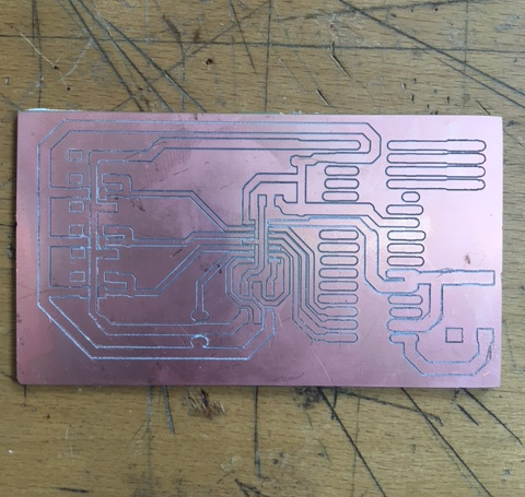
3) Copper plate for milling PCB.
4) Acrylic to be used to made the base and basket (laser cut).
5) pully & Motor Holder. (3d printed)
6) Rope or thread.
7) Box (CNC).
What Has Been Used
- Designing and printing Using 3D printering:
1- Pully.
2- Motor Holder.
- Designing and Cutting Using Laser Cutter:
1- Hanging Basket.
- Designing and cutting using Vinyl cutting.
1- Posters and stickers.
- Designing and Cutting Using CNC:
1- Base Box.
Making the Project
The following are the tasks I am working on this week, My project will consist of switches and limit switches for inputs and a motor for an output. I will include a reference to the corresponding week that contains detailed information. :
Testing the Motor:
In order to make sure that the Motor and the steeper drive works properly, I connect stepper drive with bread board and arduino circuit board to test the stepper motor. I downloaded “StepperDrivermaster” Arduino Library and tested the stepperdrive code from Arduino examples.
The result were satisfying and the motor works.
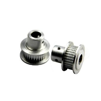
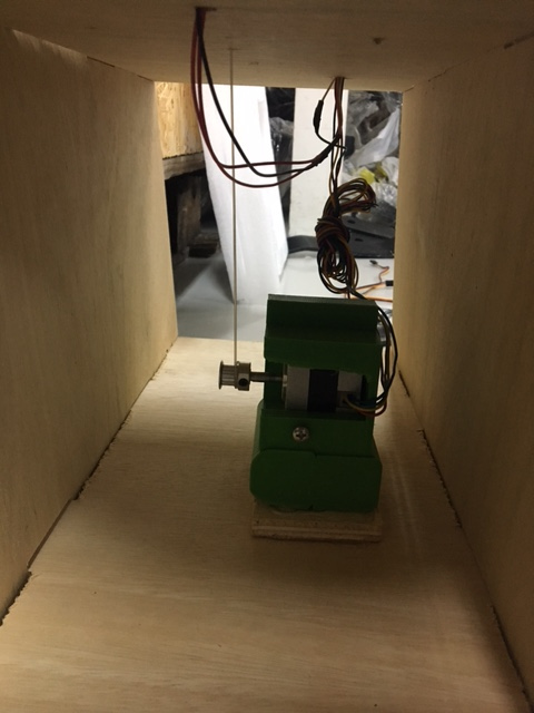
Making the Pully:
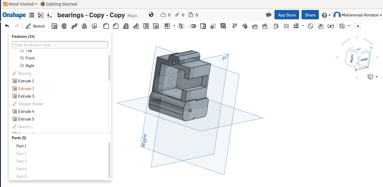
I have designed and made the pully in OnShape to be used in the final project. This pully will be carrying the basket and connect to the Motor pully.
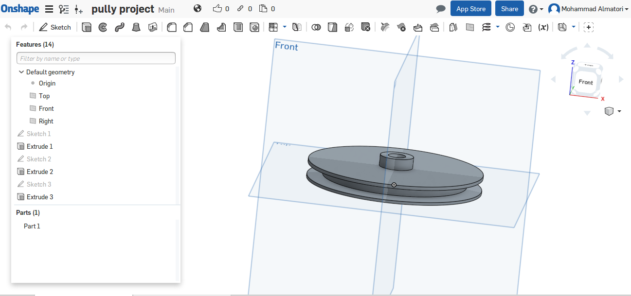
3D Print Setting:
After preparing the file in RealVision Software “Details for using RealVision” LINK HERE to 3D Scanning and Printing . We generate a .Fcode file that is readable by the 3D printer. I set the platform temperature to a range from 40 to 50 and the filament Head from 200 to 240. and upload the required file. The machine will heat and once ready it will start printing.
The idea of using the bullies was to use one bully to left the basket, and another bully to be attached to the motor shaft. I have also included in the design of the bully a screw hole in order to fix the bully with the motor. Unfortunately, Due to weight and the torque of the motor, the bully was slipping and the result was the bully standing still. Tightening the bully with the screw just made the bully hole loose as there is no thread inside the hole. Therefore I used one bully and fixed it with holder on the top of the design.

LINK HERE to 3D Scanning and Printing .
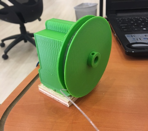
Making the Motor Holder:
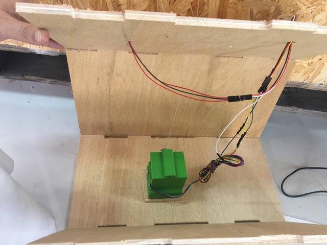
I modified a similar design I developed in the Machine week design. Although unfortunately, I lost the original design I used in the machine week by over saving on it instead of making a copy. This motor holder will be 3D printed & fixed inside a box and will contain the motor that will operate the pully.
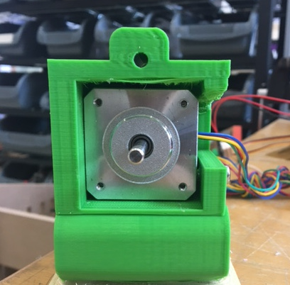
For making the motor holder, I applied the same settings mentioned in the bully 3D print settings above. As explained earlier, the bully being attached to the motor shaft did not work as expected. I have tried a ready made bully with a screw that have the same concept of my bully, Still it was slipping. Therefore, the only idea I came with is to use holder with screw and attach it with the motor.
being that this solution was successful, I had mad a hole for the rope that is connected to the motor shaft passing the bully attached at the top and holding the basket. And by fixing the motor holder to the box, I complete the assembling of the motor part.
LINK HERE to 3D Scanning and Printing .
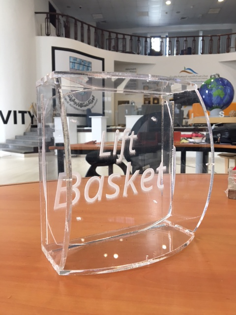
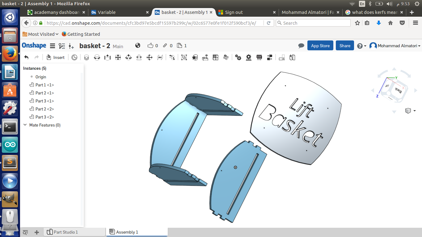
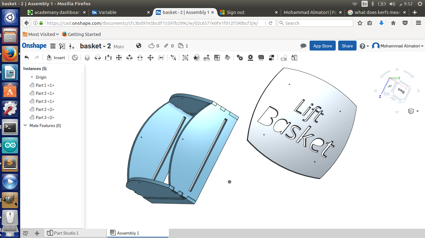
Making the basket:
I used Onshape to design a 2D basket. The pieces were made out of acrylic materials. I made sure in the design o make a press fit and include holes to prevent the basket from waving while being hanged and holes to hang the basket the pully.
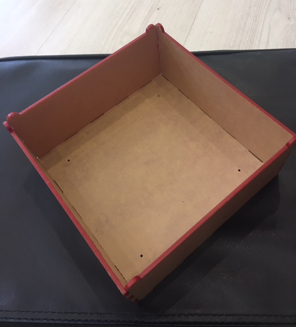
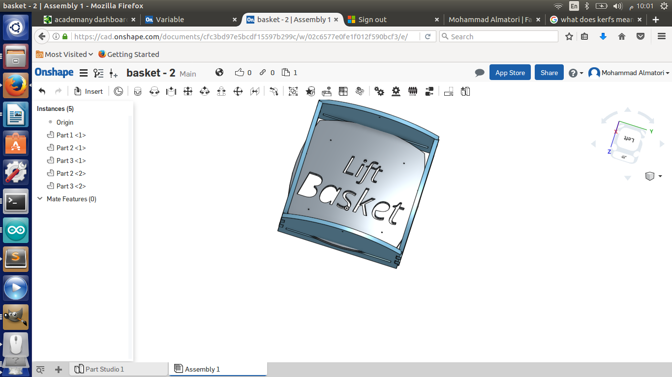
After my meeting with Mr. Neil, He requested re-design the basket. therefore, below is the new basket.
I had made two designs for a baskets. The first one is made out of acrylic 3mm, The setting for cutting was as follows:
1- The Power was set to 100%.
2- The speed was set to 40%.
In order for sturdy fit and after the fit test, t turned out that the best measurements are to add 0.25 mm for each side of the male part for example: if the female part is 5 mm the male will be 0.25 + 5 + .025 = 5.5 mm. The laser cutting part was done as per the settings mentioned above. The fit is done as per the below images.
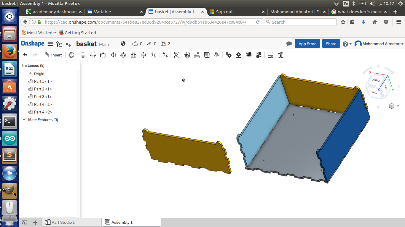
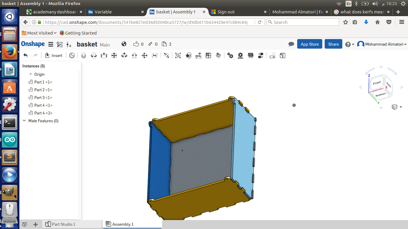
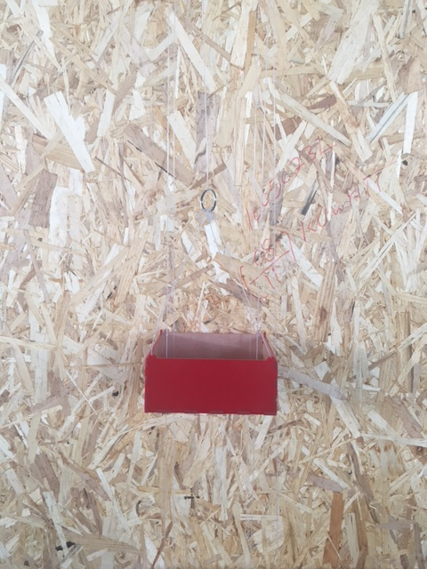
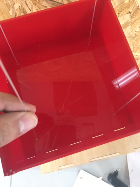
The basket was hanged by four ropes. Then the four ropes attached to a single rope which is connected to the motor shaft. Moreover, the base of the basket has four through holes. Passing though these holes another rope in each. This will help the basket to maintain a centered location in a windy environment.
The flow of the design is that the base might fall due the the extra weight. Therefore, the second design fixed this flow and added the nice to look touch. In the second design I used 6 mm acrylic and the setting were as follows:
Engraving:
1- The Power was set to 70%.
2- The speed was set to 40%.
Cutting:
1- The Power was set to 100%.
2- The speed was set to 20%.
I used the same fit method and measurements mentioned the first design. Except that for the base I made it in away to slide in before connecting the edges and get prevented to slide out after assembling the basket. I maintained the same concept of centering the basket with 4 ropes passing though the base of the basket.
LINK HERE to computer-controlled cutting .
Making Stickers:
I made some stickers for the project using Vinyl Cutting.
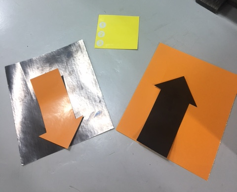
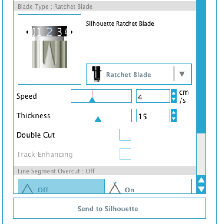
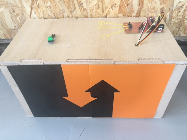
In regards the Vinyl Cutting, I choose the design to match my poster. Therefore, the stickers components were simple. It was just arrow and numbers indicators for the switches on circuit board. The settings I used for the Silhouette printer and its software is as follows:
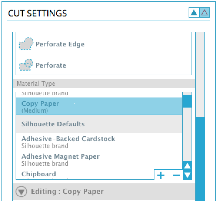
First we choose the paper type, which in our case the most close option is copy paper. Then we choose the speed, thickness and the blade type. In this scenario I choose, Blade 2, Speed 4 and thickness 15 as shown below.
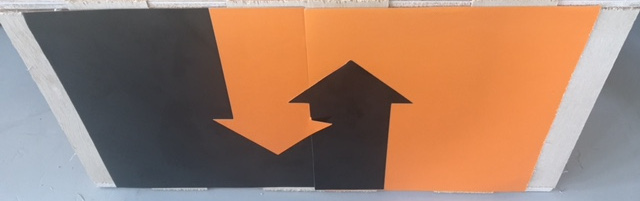
As I said earlier, I took orange and black sticker paper. Cut an arrow from both. Then took a new sheets of both orange and black stickers and overlapped the colors.
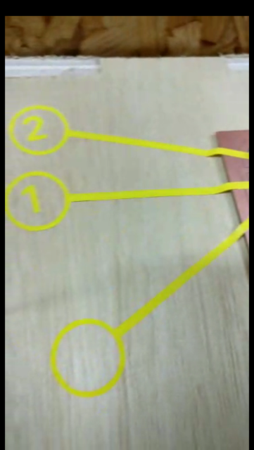
in regards the circuit board, I used each sticker next to switch tha leads the basket to the higher floors.
LINK HERE to computer-controlled cutting .
Making the Box:
I used Onshape to design a 2D Box. The pieces were made out of Polywood materials. I made sure in the design o make a press fit. The Circuit Board will be fixed on the box. Moreover, the Motor Holder will be fixed inside the box.
LINK HERE to Computer-Controlled Machining .
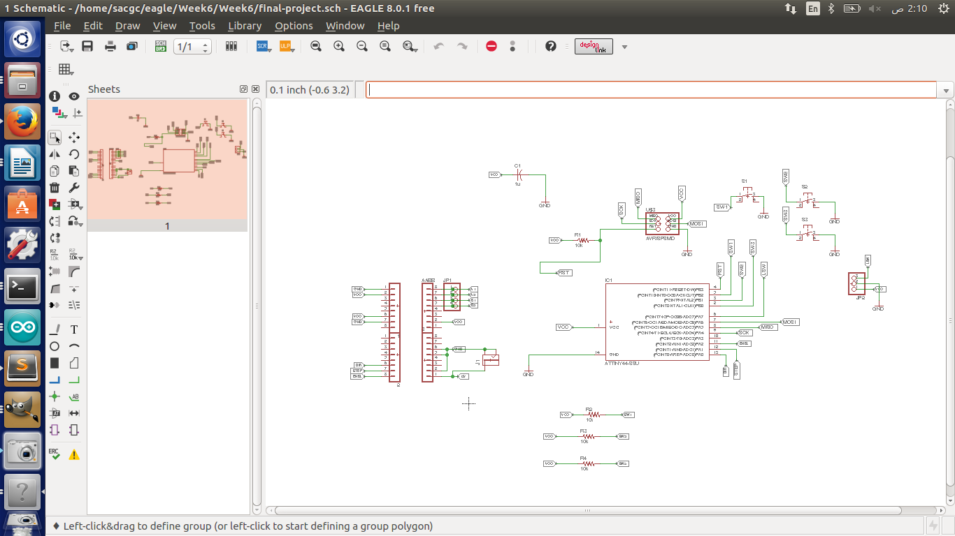
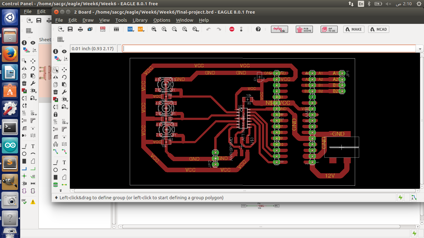
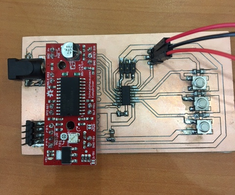
Making the Circuit Board:
In order to create my circuit board I made several considerations such as: what components to be soldered, what ATTiny or Chip is required based on the number of pins and memory that is going to be used. How to include the stepper drive in the circuit board.
I will explain first the stepper drive connections. The stepper drive I am using is “EasyDriver - Stepper Motor Driver – ROB-12779” It has a total of 17 pins. The details description of each pin is LINK HERE .
In order to merge the stepper drive with the Circuit Board it was require to connect some pins to ground, VCC in order to set them to high or low. In addition to connect the signal pins such as Step, DIR and Enable. Not to mention the motor 4 pins cables. Therefore, I made all the required connections embedded with my circuit board.
I had connected a power Socket to The Stepper Drive to collect a 12 volt which is required to run the stepper motor. Moreover, the stepper drive itself generate an output power of 5 volt, that i have used to feed the Attiny 44 and my circuit board.
I had included all other required components such as switches, reseters,...etc. And made the design of the switches to connect the signal while it is LOW.
In order to arrange the fitting of the stepper drive. I placed 16x2 Male to Female pins for the stepper drive. Yet, I misplaced the DIR pin with Ground Pin. Therefore, In the code. I Set what is supposed to be DIR to ground. And I used the Enable pin as DIR.
LINK HERE to Electronics design .
LINK HERE to Electronic Production .
LINK HERE to Input device .
LINK HERE to output device .
Programming the Board:
My board contains the following, Three switches that represent Ground, First floor, Second Floor and limit switch. Once power plugged, the basket moves to “Home” till it hit the limit switch. Then waits for the input from the user and behave as normal lefts. Below is the code used to program it.
#include "BasicStepperDriver.h"
#define MOTOR_STEPS 200
// All the wires needed for full functionality
#define DIR 2
#define STEP 1
#define G 0
//#define MICROSTEPS 1
BasicStepperDriver stepper(MOTOR_STEPS, DIR, STEP);
int pFloor = 0;
int tFloor = 0;
const int sw1 = 8;
const int sw2 = 9;
const int sw3 = 10;
const int Lsw = 7;
const int stepNumber = 200;
void goHome() {
while (digitalRead(Lsw) == HIGH) {
stepper.rotate(-1.8);
}
pFloor = 0;
}
void goUp() {
for (int i = 0; i < stepNumber; i++) {
stepper.rotate(18);
}
pFloor++;
}
void goDown() {
for (int i = 0; i < stepNumber; i++) {
stepper.rotate(-18);
}
pFloor--;
}
void setup() {
pinMode(G, OUTPUT);
digitalWrite(G, LOW);
pinMode(sw1, INPUT);
pinMode(sw2, INPUT);
pinMode(sw3, INPUT);
pinMode(Lsw, INPUT);
stepper.setRPM(120);
goHome();
}
void loop() {
if (digitalRead(sw1) == LOW) { // ground floor
tFloor = 0;
} else if (digitalRead(sw2) == LOW) { //floor 1
tFloor = 1;
} else if (digitalRead(sw3) == LOW) { // floor 2
tFloor = 2;
}
if (tFloor > pFloor) goUp();
if (tFloor < pFloor) goDown();
}"
I had Made a gohome() functions which start at the begging till it touch the limit switch and set a variable pFloor = 0. then the program awaits the user to click a switch. another variable is used "tFloor". a function later is used to identify the current floor location and distination floor by comparing the two variables.
LINK HERE to Embedded Programming .
Chosen license for The Project
I will use Creative Common with the following:
1) Attribution (BY).
2) Non-Commercial (NC).
3) No Derivative Works (ND).

LINK HERE to Invention, Intellectual Property and Business Models .
Gratitude
I would like to express my sincere thanks to whomever helped/supported me in any mean during my trip in FAB Lab. Especially my lab instructors, Colleagues, Mr.Francis and Mr.Neil for their continuously sharing their gained knowledge over the years. And I hope I can pass on my gained knowledge to a next generation of Fab Lab.
Downloaded files
Final Project Poster
Board Schematic
Board BRD
Stepper Drive Info. Link
Stepper Motor Info. Link
Pully Design Link
Motor Holder Design Link
Basket Design Link
Box Design Link