Output Devices
Introduction
In this output week, I choose to implement the RGB output. There are many outputs devices such as Stepper Motors, Verso Motors, DC Motors, LED, LCD, speaker ...etc. Before I show my implementation, let me introduce some informations that helped me to make my final circuit board.
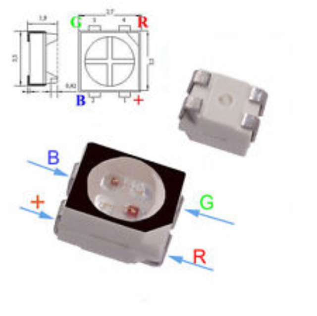
First of all lets get familiar with the RGB light. The RGB LED we are using is “LED RGB DIFFUSED 4PLCC SMD” it has four pins and three colors “RED, BLUE, Green and Vcc” the detail pin locations are shown below.
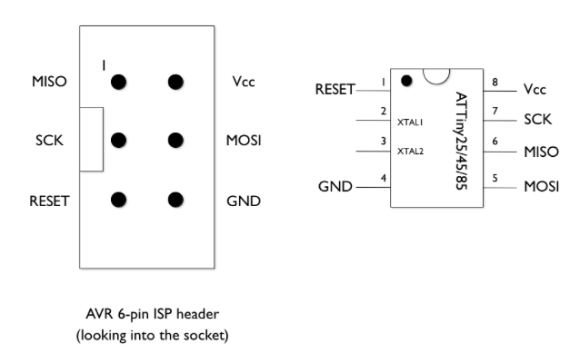
Moreover, I will be using ATTiny45 for this week and for the later connection and for identifying the pin numbers for the programming I will be utilizing the following image:
Assignment
The assignment for this week is to:
1- Design Circuit Board with RGB output using Eagle Cad.
2- Solder the elements into the Circuit Board.
3- Program the board.
4- Test the board.
My Work
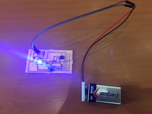
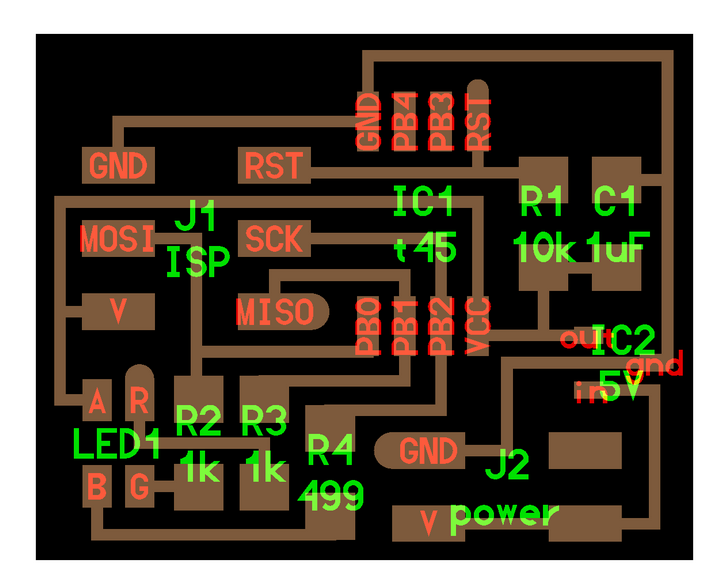
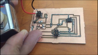
I started this week by designing my Circuit Board using Eagle Cad Schematic Design, Then I crated my Board file. I tried to connect the routes manually but I could not and to avoid doing bridges with zero Ohm I did automatic routing then I manually fixed the routes and increased their sizes.
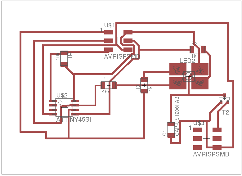
I printed my Circuit Board the Soldered all the elements with the following notes. I used 2x3 header instead of the 2x2 header as I could not found during the schematic design. After finishing the soldering I did the regular check to make sure no short circuit in the board. I connected my circuit board to the USB Tiny to start the programming and smoke came out! I disconnected the circuit and checked every element to make sure there is no short circuit. Connected it again with the USB tiny and smoke came out from the regulator. I checked the design in the schematic and I noticed that I made a wrong connection for the regulator by swapping the connection of the ground and the Vcc that is connected to the micro controller. So I manually cut out the routes and made short manual connections to fix the route issue.
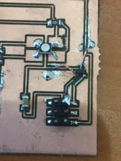
I connected it again with the USB tiny, downloaded the program and it worked.
Programming the Board
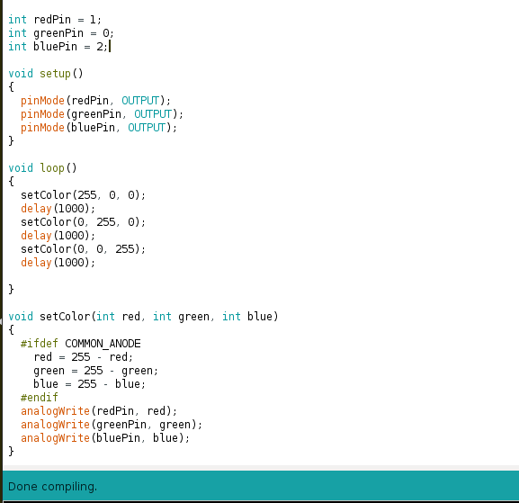
before I share the program code lets first share the following information. The basic idea of using RGB light is to generate many colors other than Green, Blue and Red. By mixing 2 or 3 of the mentioned colors we can generate different colors.
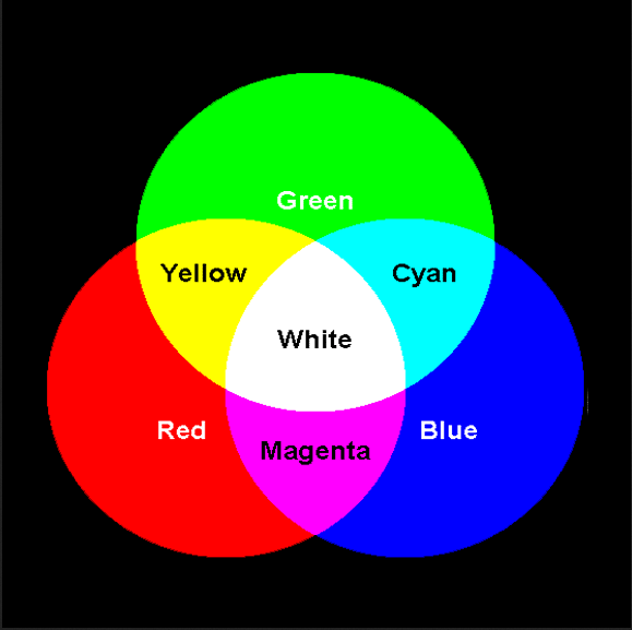
understanding the mentioned above concept, we will apply the same in our following program. As you notice the code have numbers such as 255, 0, 80. For each of the three colors, number 255 means that the referenced color will get its maximum brightness while zero means it will be off. And accordingly any number between 0-255 of two of the three colors means we are generating a new color as shown in the image above.
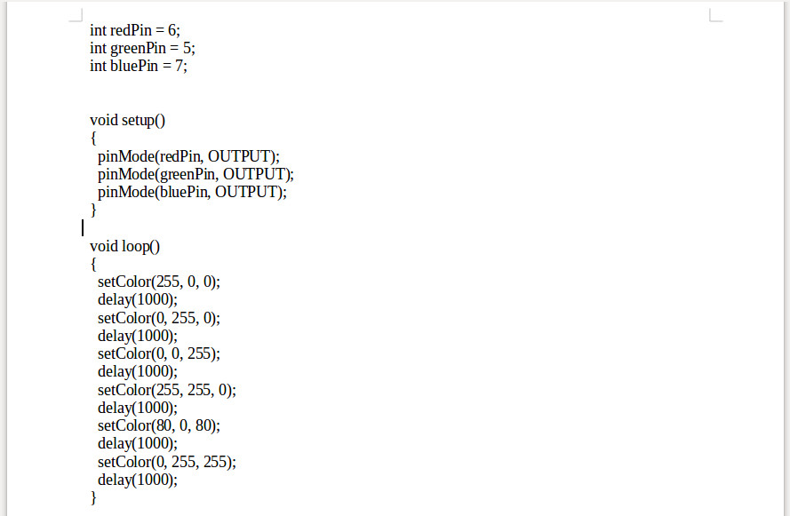
Moreover, I will change the colors in the code and notice the changes in the colors.
Fixing The Colors
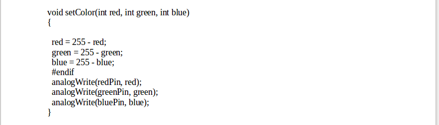
I noticed that the RGB light as shown in the video above dose not show all three colors. So I re-investigate the issue and noticed the following. In the Schematic design I used different type RGB element so replaced that item. In the same time I fixed the connection with the regulator. I re-soldered all the elements and tested the new board and all the three colors are working now. Shown below the code for testing the three colors and videos.
Download Files
OLD Schematic Design
OLD Board File
NEW Schematic Design
NEW Board File