WEEK 15 - NETWORKING AND COMMUNICATIONS
ASSIGNMENT
- Design and build a wired and/or wireless network connecting at least two processors.
MAKING AND TESTING THE HELLO BUS BOARDS
I was going to make a test with Neils boards before I was going to make mine. I downloaded Neils PNG files of the hello-bus-45 board from networking and communications, week 15 on the Fab academy 2017 website.
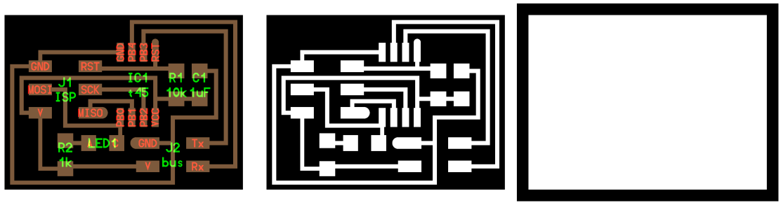
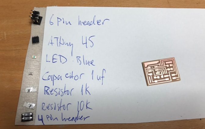
I collected all the components I needed for the board and soldered it. All the components are on the image below for the board. For more details on how to make a circuit board see the documentation in week 4 or week 6. I did not use a blue LED like it's written below, I used an orange LED.
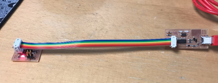
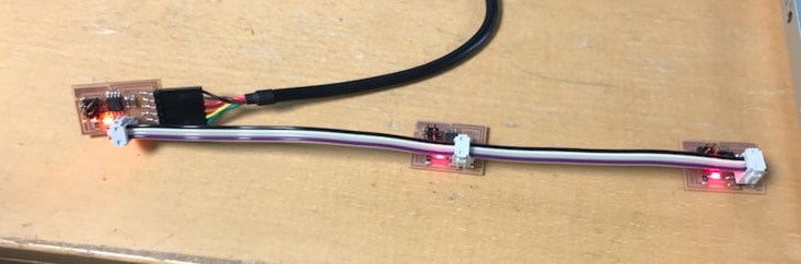
I made two hello bus 45 boards, called slave 1 and slave 2. I started programming one at a time with the Fab ISP I made in week 4. This is how the cable should be while programming.
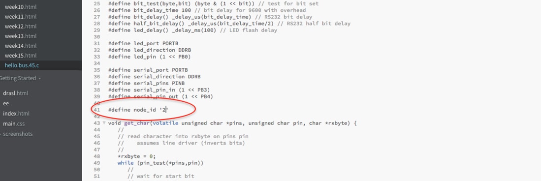
I programmed the board with C code that Neil put on the website, you can download the C code and the make file here, the name is hello.bus.45.c and makefile. I made a folder that I named Bus and put the C code and the makefile there. I opened the C code in Brackets and changed the node (#define node_id '2') from the board I was programming. The first board (Master) had the node id 0, the second board (slave 1) had the node id 1 and the third board (slave 2) had the node id 2. I was programming slave 2 on the image below, you can see that by the number in the red cirlce.
I made new terminal at folder (command window in Windows) and wrote the following commands:
make -f hello.bus.45.make
make -f hello.bus.45.make program-usbtiny-fuses
make -f hello.bus.45.make program-usbtiny
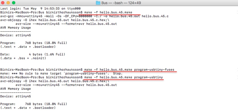
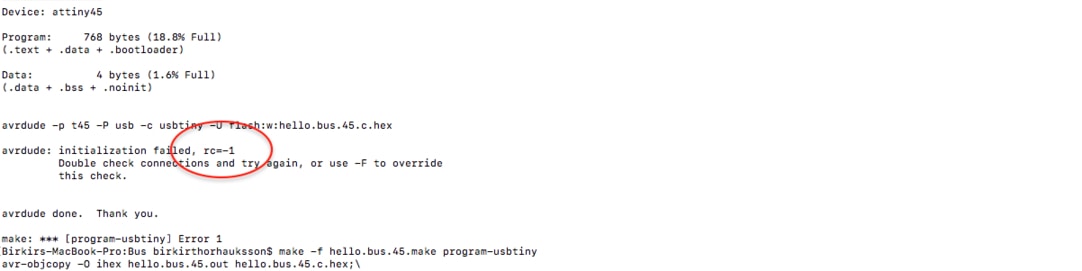
When I was programming one of the slave boards it didn't connect right so I got error, which you can see in the red circle (rc=1), so I just made sure everything was connected right than it worked.
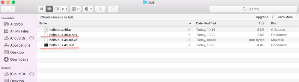
Every time I programmed a board, two new files were created each time, hex and out files. I deleted those file each time I programmed, except for the last board.
When I had programmed all the boards I connected them together.
Then I checked if the boards worked together by opening Arduino and going to Tools --> Serial Monitor, or use the quick way shift/command/M to open a serial window.
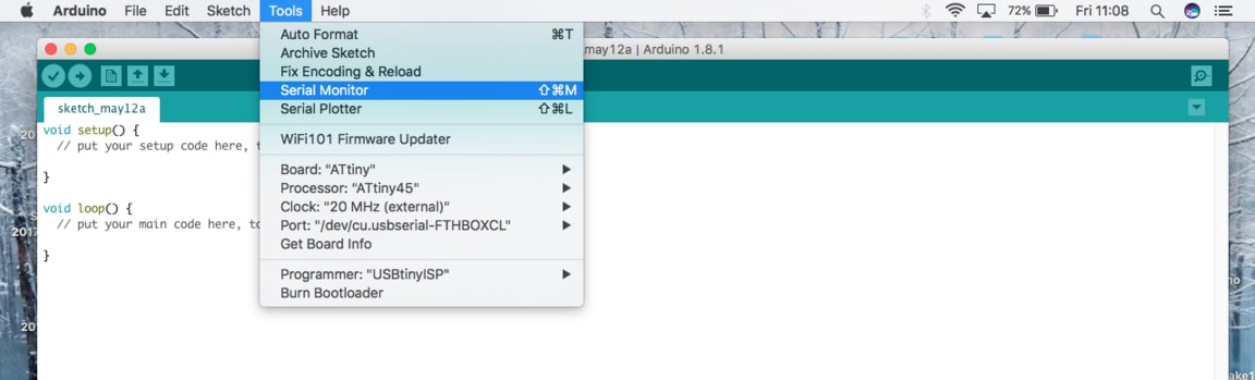
When I enter the number of the node in the serial port and send it, all the boards bling their LED once and the board that corresponded to its number lights up again. So I'm basically communicate with the board I write to.
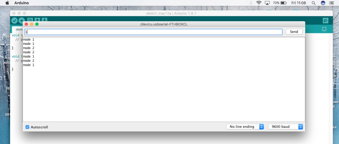
On this video I'm typing the number 1 which is the board in the middle (slave 1) and as you can see they all blink once at the same time and then the middle board blinks again.
Bus Board from BirkirThor on Vimeo.
MAKING BUS BOARD WITH RGB LED
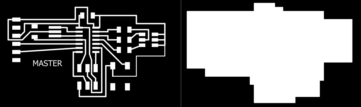
I decided use a board I made in week 10. This will be the master board communicating with the slave boards. The differences is that I took both of the 4 pin headers of and added the FTDI cable. For more details how to make a circuit board go to week 7, electronics designs.
I should have taken the button away because there was no need for it in this project.
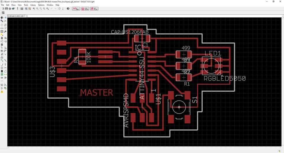
This is how it looks like. You can download the the files below in Download Files.
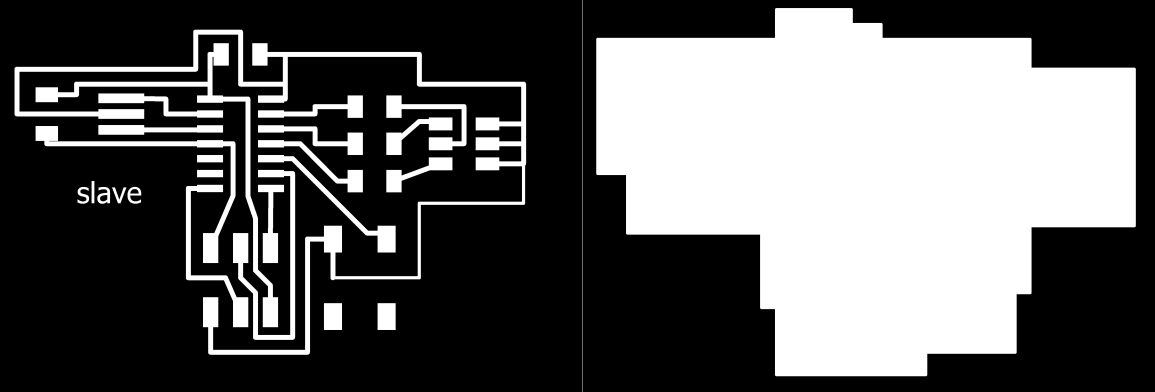
Then I made the slave board, I only had to do one because I had a similar board that I could use. But it's also really similar to the board from week 7, took both of the 4 pin headers of and for this board there was no need to have a FTDI cable, because it would get VCC from the master.
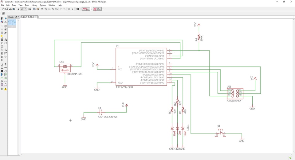
This is how it looks like in the schematic and I also should have taken the button away.
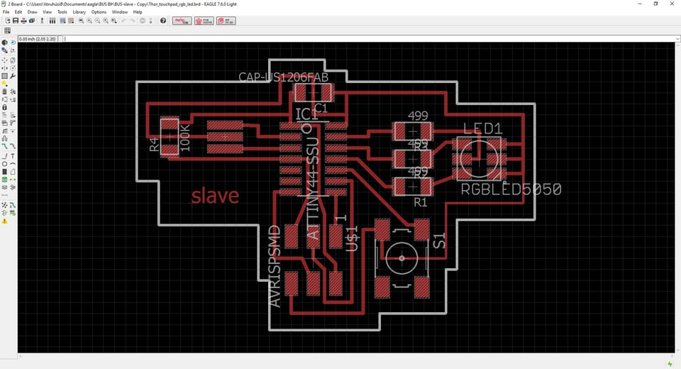
This is how it looks like. You can download the the files below in Download files.
TESTING THE BOARDS
Then I collected all the components. It was the same list I had used before so I crossed over those I didn't need. There are two zero resistors there that I didn't need.

The LED lights on the master- and slave board were not right. They should have turned like the one on the Thor board, see in the red circle were the little triangle should be. So I turned the other LED lights 180° so they would have right connection with the microcontroller. The green circles should be on the same side like the red circle.
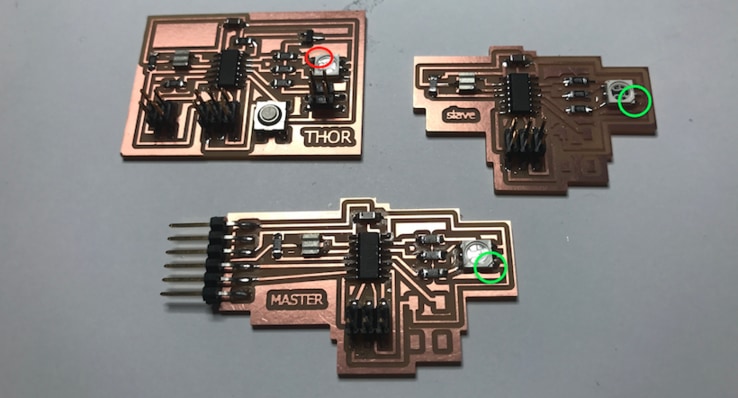
I ran an Arduino code on them just to check if the boards were working right, and they were. You can download the code below. Next step was to program the boards, connect them together and learn more about networking and communications in the process.
SERIAL COMMUNICATIONS TROUBLE - USING OSCILLOSCOPE
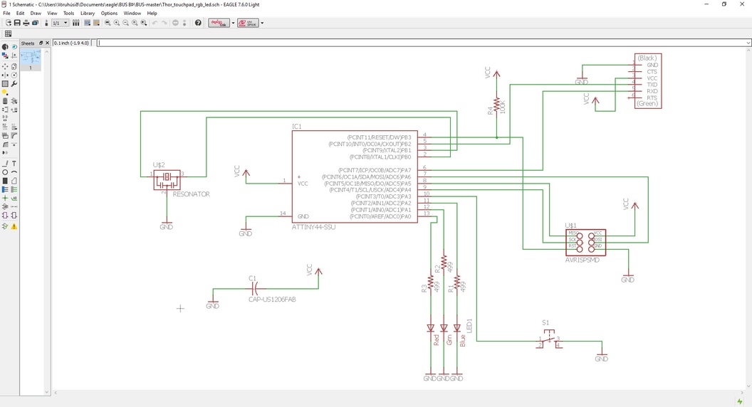
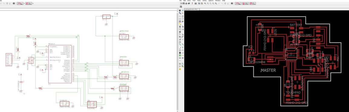
This is the schematic of my master board that I will use in my final project. There are more information about this board in Week 19, Project Development. I did not make this board in this week but I put the documentation here because it has to do with networking and communications.
I was having some serial communication trouble between my master board and LED boards (slaves). Me and my Fab Academy instructors had been trying to find out what the problems were for some time and in many different ways. We had to get an oscilloscope to see if we are getting the right signals.
Arduino codes for this project can be downloaded in Download Files in week 19.
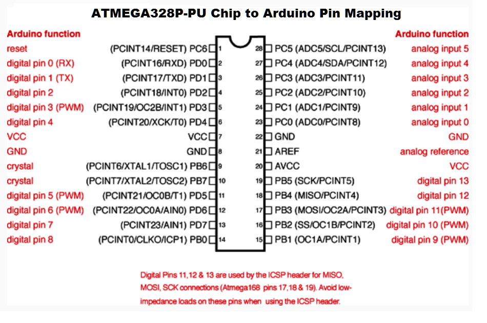
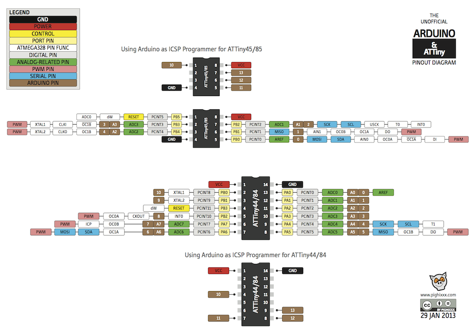
It is necessary to have the right pin configuration when programming in Arduino or else it wont work. The image below is a pin configuration for the ATMEGA328 microcontroller.
Here is an image of the pin configuration for the ATtiny44 and ATtiny 45 that I used when I was programming the LED boards and the sound sensor board.
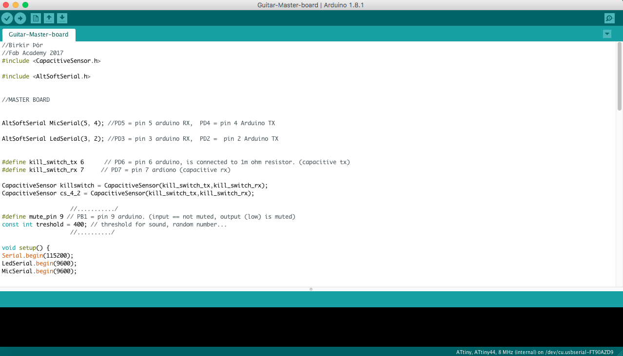
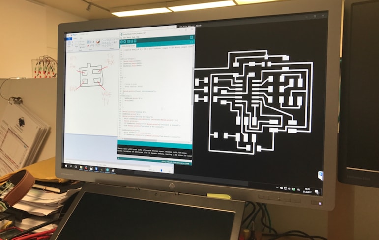
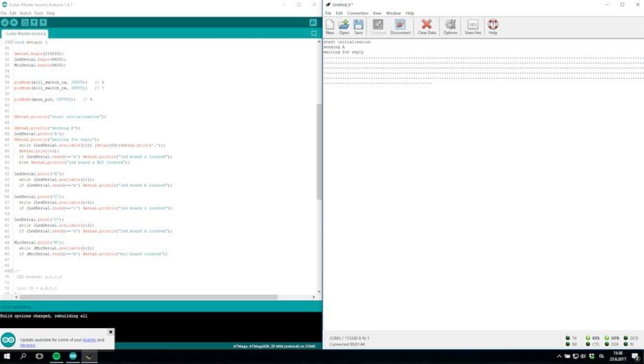
This is a part of the master board code in Arduino. I inclueded CapacitiveSensor.h and AltSoftserial.h that I use and define the pin configuration by looking at the schematic I had made and the pin figuration image above.
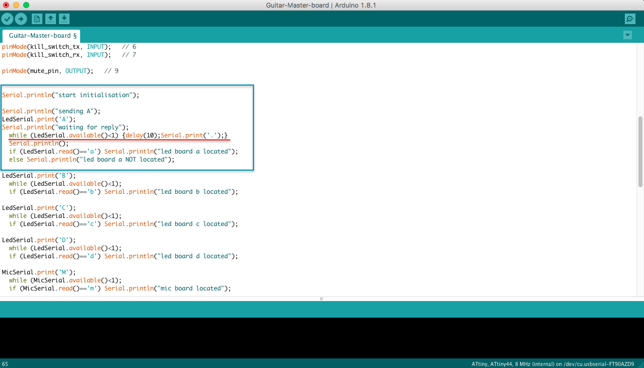
This is the same code as above. Here I'm communicating the other boards with serial. I've been having some troubles with serial communications which I didn't find out during the Fab Academy 2017. But in the blue box is the test I had been using to find out if I was Receiving anything or not. Unfortunately I didn't receive anything from the LED boards, more information about that below.
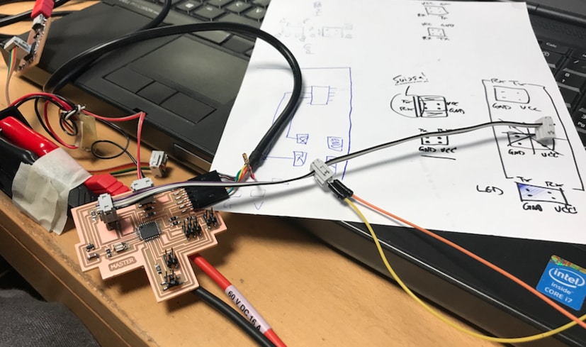
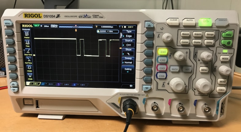
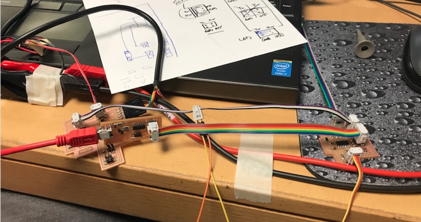
I am using a power supply to power everyting so I don't have to finish my battery on this. The VCC (red wire) has been removed on the FTDI cable so it wont overheat the 5v regulator. This is how the setup is for this experiment on the master board. I am using another FTDI cable which I connect two wires in, TX and RX to see if I am getting any signal from them. I got a normal signal from this, see on the image below.
This is a photo of the oscilloscope of the signal when I send big A from serial monitor.
Here I am doing the same with one of the LED boards. On the image I am programming it.
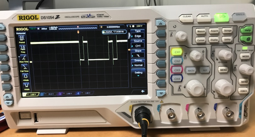
This image shows a normal signal when sending from serial monitor to RX.
When we connect the master board and the LED boards together the TX (transmitter) sends but doesn't get answer back. Like when I send big A from serial monitor and should get little a, it doesn't happen. That's were the problem is. We have been using multimeter and oscilloscope and trying everything we know.
On the image we are going threw the pin figuration and if TX and RX are correct, which it was.
Here I am waiting for reply from the slave A (LED board) but I'm not getting any.
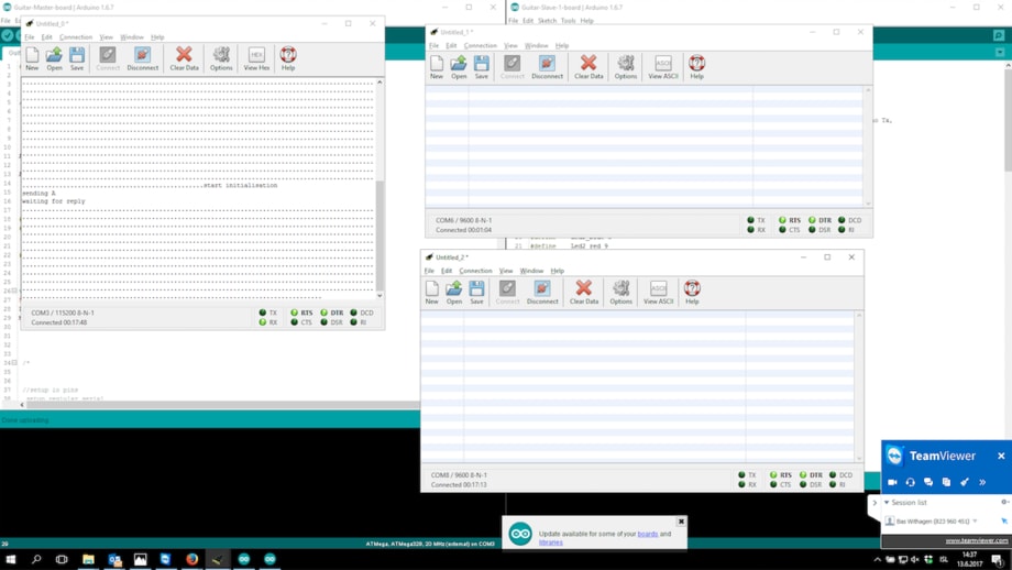
There I'm using three FTDI cables to check if I was getting any signal. One FTDI cable was connect to the master board and one to TX and the other to RX. On the serial monitor to the master is waiting for reply but the other to the right aren't showing anything. One window is serial monitor in Arduino and the two other are CoolTerm.
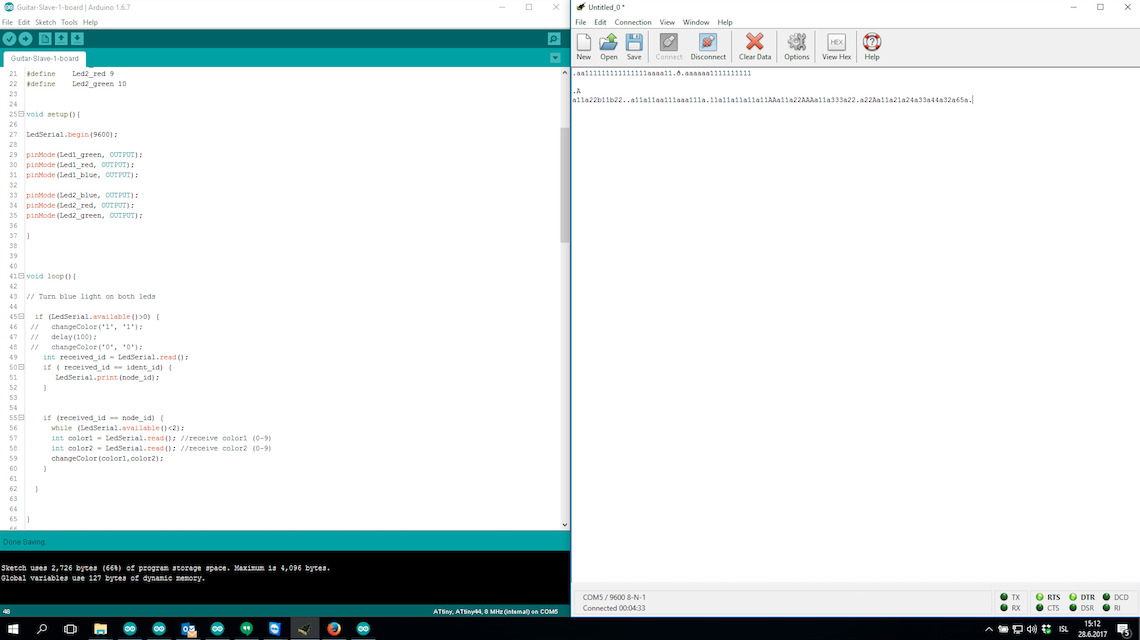
I got a respond from the LED board (slave). I was using three FTDI cables and sending node id from a serial monitor from the computer, I was not using the master in this test. When I send capital letter the board with the same letter responds with the same letter, just the small one.
LED Serial from BirkirThor on Vimeo.
FINAL TEST
We found out that there is something wrong with the rx pin on the LED board. We can send information and change color but no respond from the boards. We also found out that one of the LED boards had a short circuit. In the CoolTerm window on the right I am writing colors so the LEDs change colors. Video below.
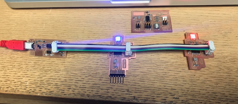
This is how everyting is connected. I am using power supply to power the boards and sending from the terminal threw the FTDI cable to the LED boards.
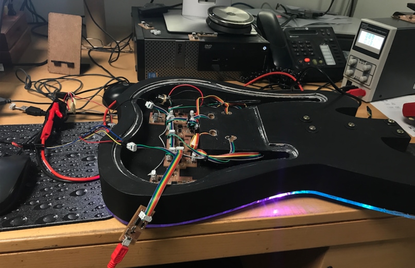
This is how it works.
LED CoolTerm from BirkirThor on Vimeo.
Here is a video showing when I write the LEDs id in the CoolTerm window and get respond from the LED board.
Respond_Fab Lab from BirkirThor on Vimeo.
RELATED LINKS
DOWNLOAD FILES
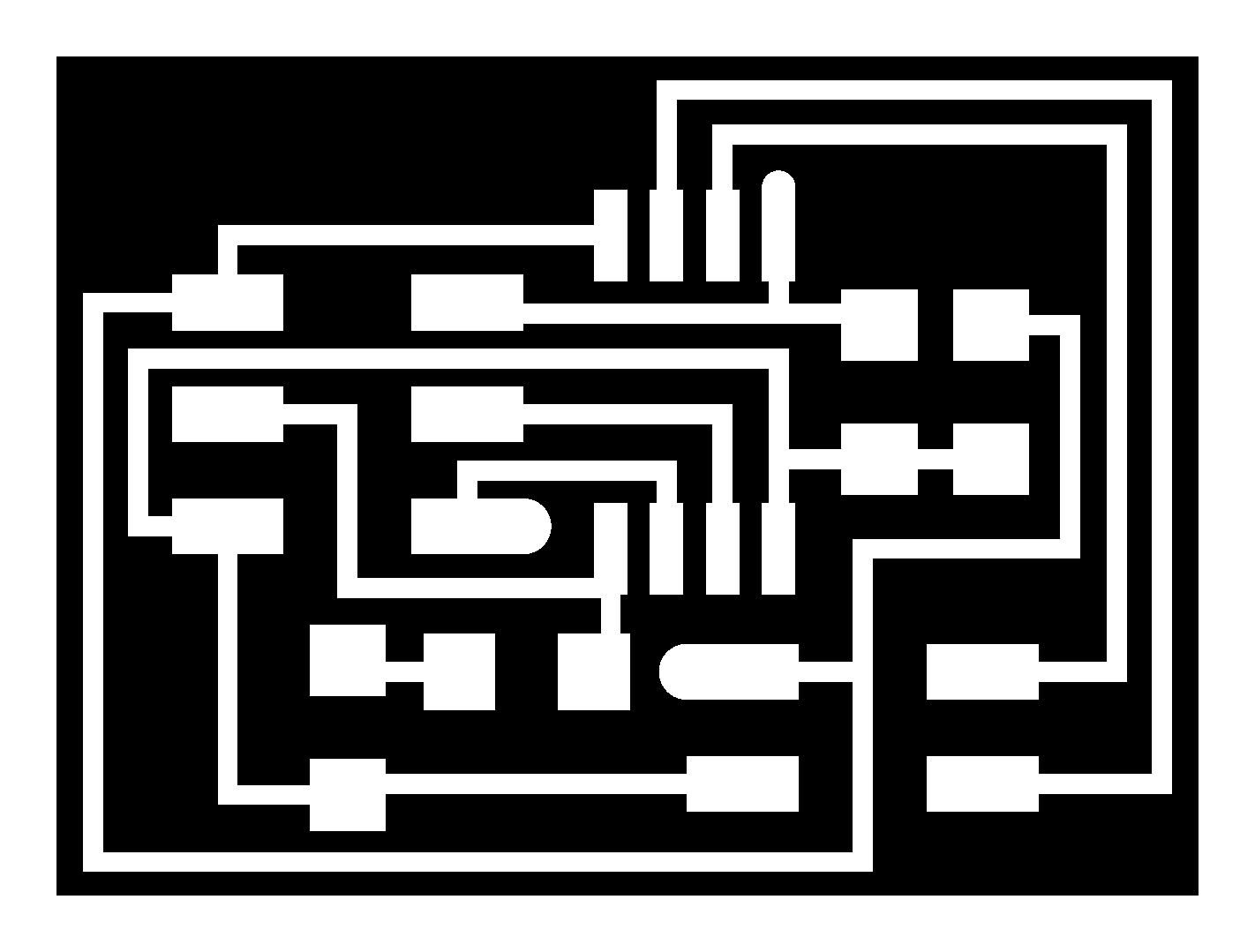
Hello Bus 45 Traces - Right click to download
Hello Bus 45 Interior - Right click to download
Master Traces- Right click to download
Master Interior- Right click to download
Slave Traces- Right click to download
Slave Interior- Right click to download
RGB LED Test - Right click to download
Touchpad I Schematic - Right click to download
FINAL PROJECT ARDUINO CODES:
Master Arduino Code - Right click to download
Mic/Sound Sensor Arduino Code - Right click to download
LED/Slave Arduino Code - Right click to download
LED Lights(No Serial) Arduino Code - Right click to download
LED Lights Test (Terminal Window) Arduino Code - Right click to download
HAVE QUESTIONS?
Contact me!
Höfn, Iceland
Email: birkirthorhauksson@gmail.com
Swing by for a cup of , or send me a message :)