WEEK 6 - ELECTRONICS DESIGNS
ASSIGNMENT
- Redraw the echo hello-world board
- Add at least a button and LED (with current-limiting resistor)
- Extra credit for simulate its operation and measure its operation
DRAWING THE ECHO HELLO-WORLD BOARD
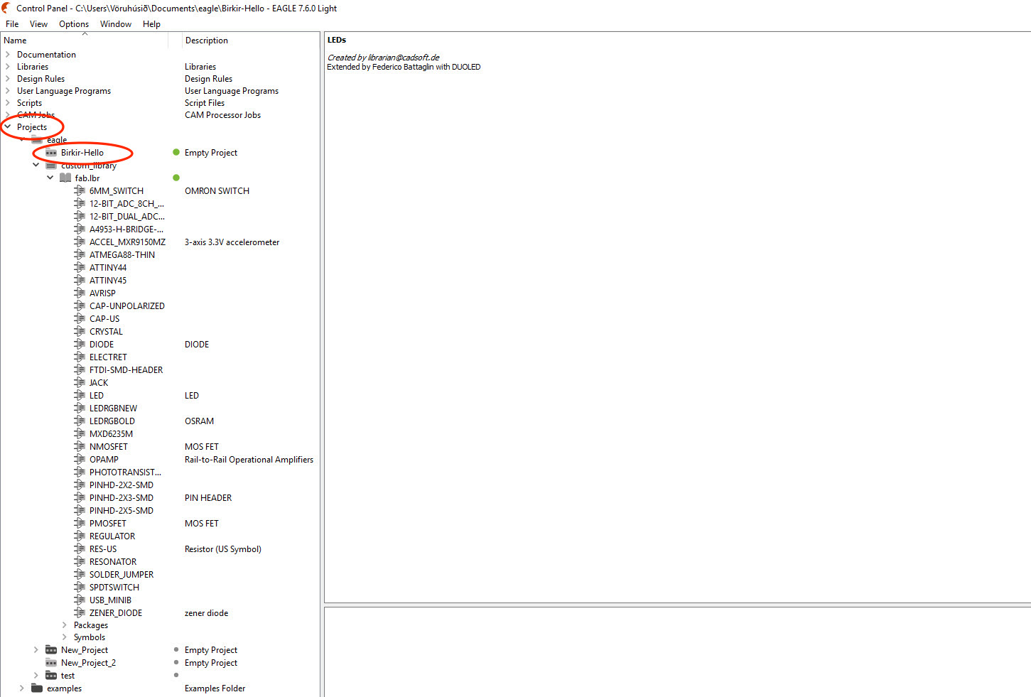
I decided to draw the Hello-world board in one of the computer in the Fab lab office using Windows. I used the software Eagle to draw the hello-world board. I started making a project folder that I named Birkir-Hello and then I right-clicked on that folder and made a Schematic folder that I would work in.
Then I clicked on the add button (in the circle on the left) and selected all the components that I needed. You can also write add on the command window and it will open the same window.Libraries are folders that contains components, they can be downloaded online and put in the eagle folder so they will be available for use. I was fab, LED and supply1 libraries.
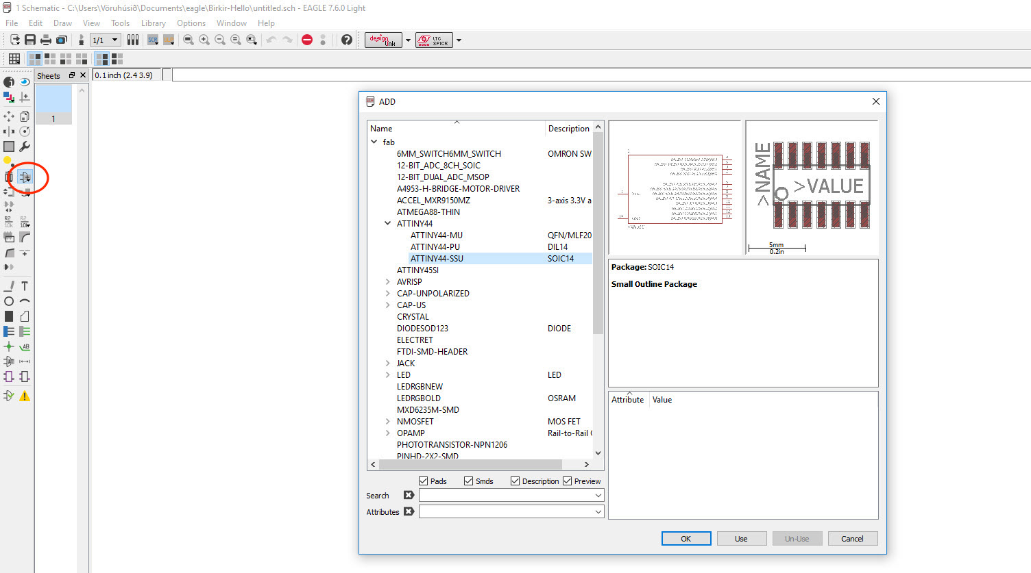
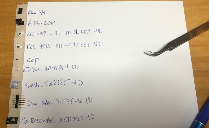
The following components are those I selected from the libraries:
Fab: ATTINY44-SSU, AVRISPSMD, CAP-US1206FAB, FTDI-SMD-HEADER, 6MM_SWITCH6MM_SWITCH, RES-US120FAB, RESONATOR
LED: LEDSMT1206
Supply1: VCC, GND (not components, + and - )
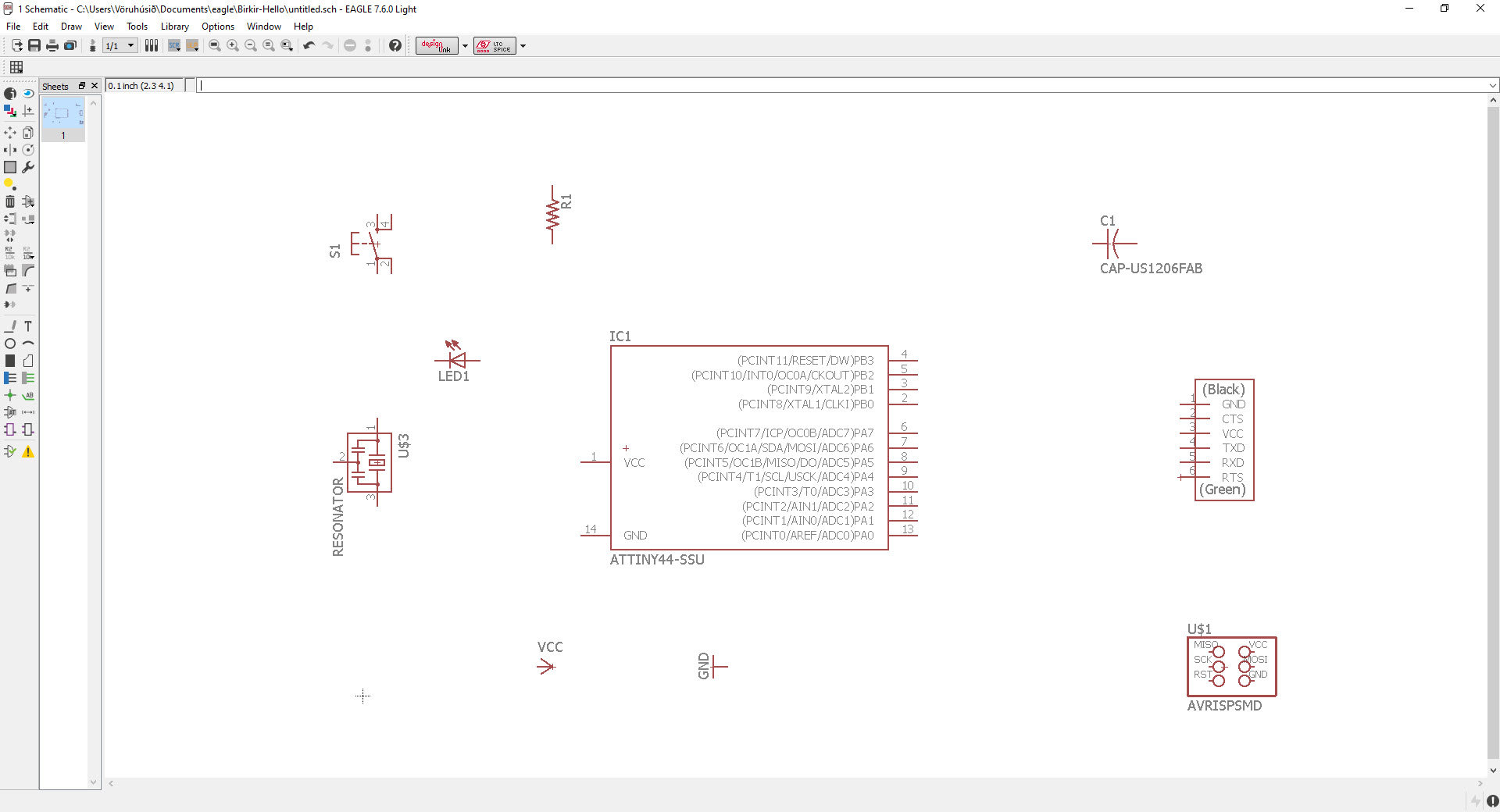
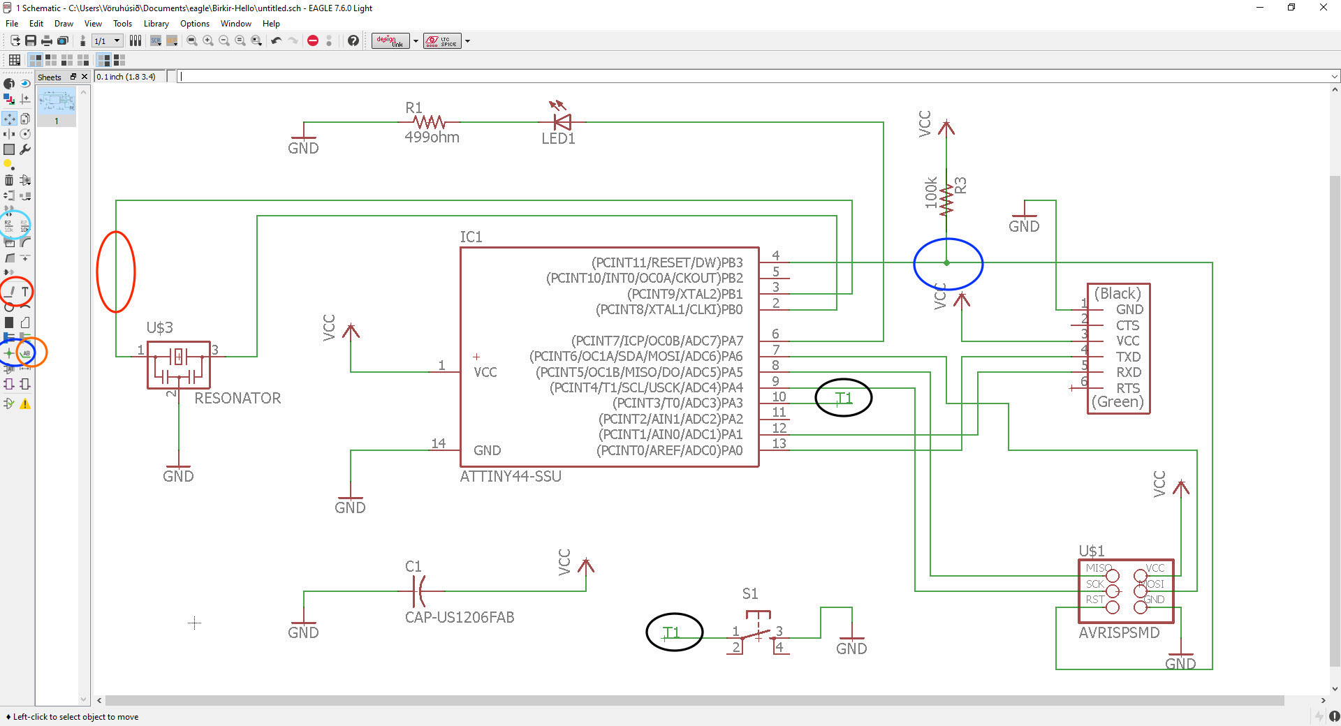
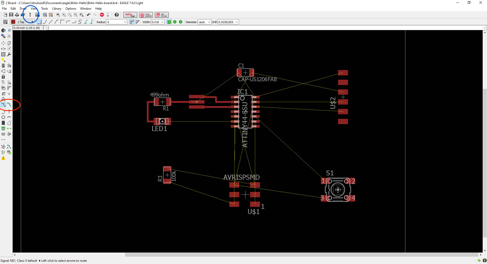
When I had selected all the components I had to connect them by selecting the button wire (the button in the red circle on the left) so it would form green lines. The lines T1 (in the black cirlce) are not visually connected so I had to connect them by clicking the label button (orange circle on the left) and click on the both lines. Then I named them T1 by clicking the name button (light blue circle on the left).
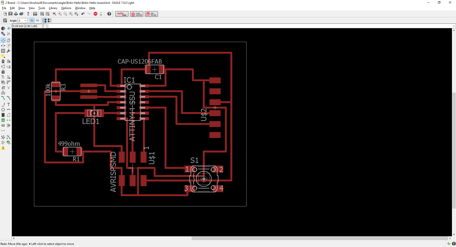
The next step was to draw the traces between components. But first I clicked on the Generate/switch to board button (in the blue circle on the top) and a new window opened so I was ready to draw. To draw the lines I had to click on the Route button (in the red circle on the left) and to delete the lines use the Ripup button next to it. The lines could not cross eachother (except they are going to the same place) so it was really difficult to find a right way for every trace. Some of the lines could go under some components.
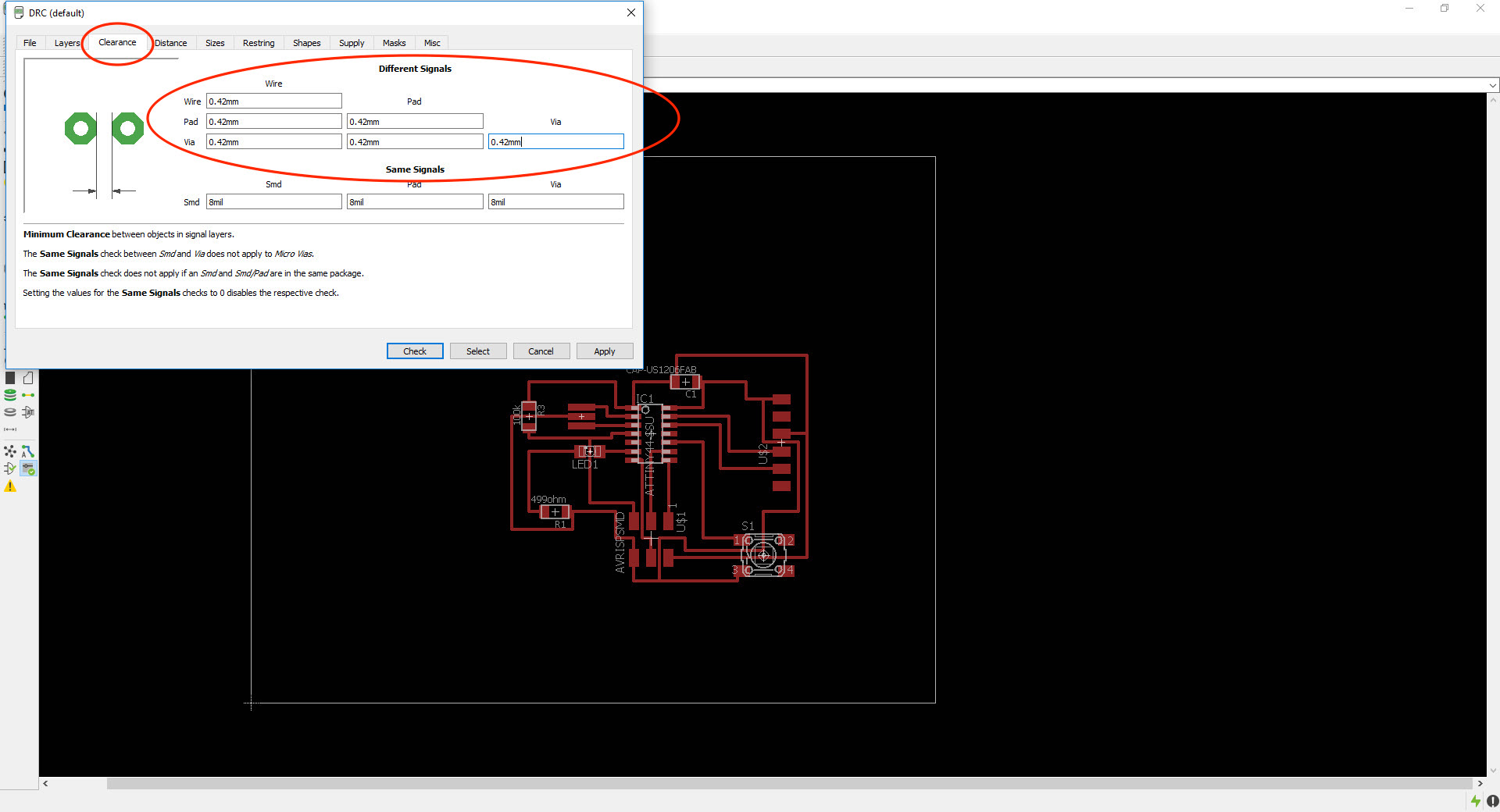
Then I had to set the settings for the traces by going to tools and DRC. The DRC window opened and I had to put the numbers in the clearance to 0.42 mm in the different signals (in the red circle).
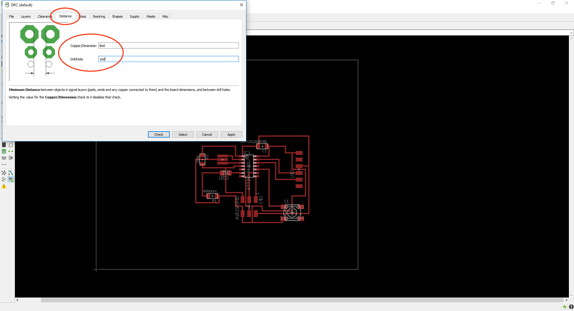
Then I put the number for the distance tap to 8 mil and 1 mil.
Then in sizes I put them to 10 mil, 0,8mm, 9,9mm and 0,5.

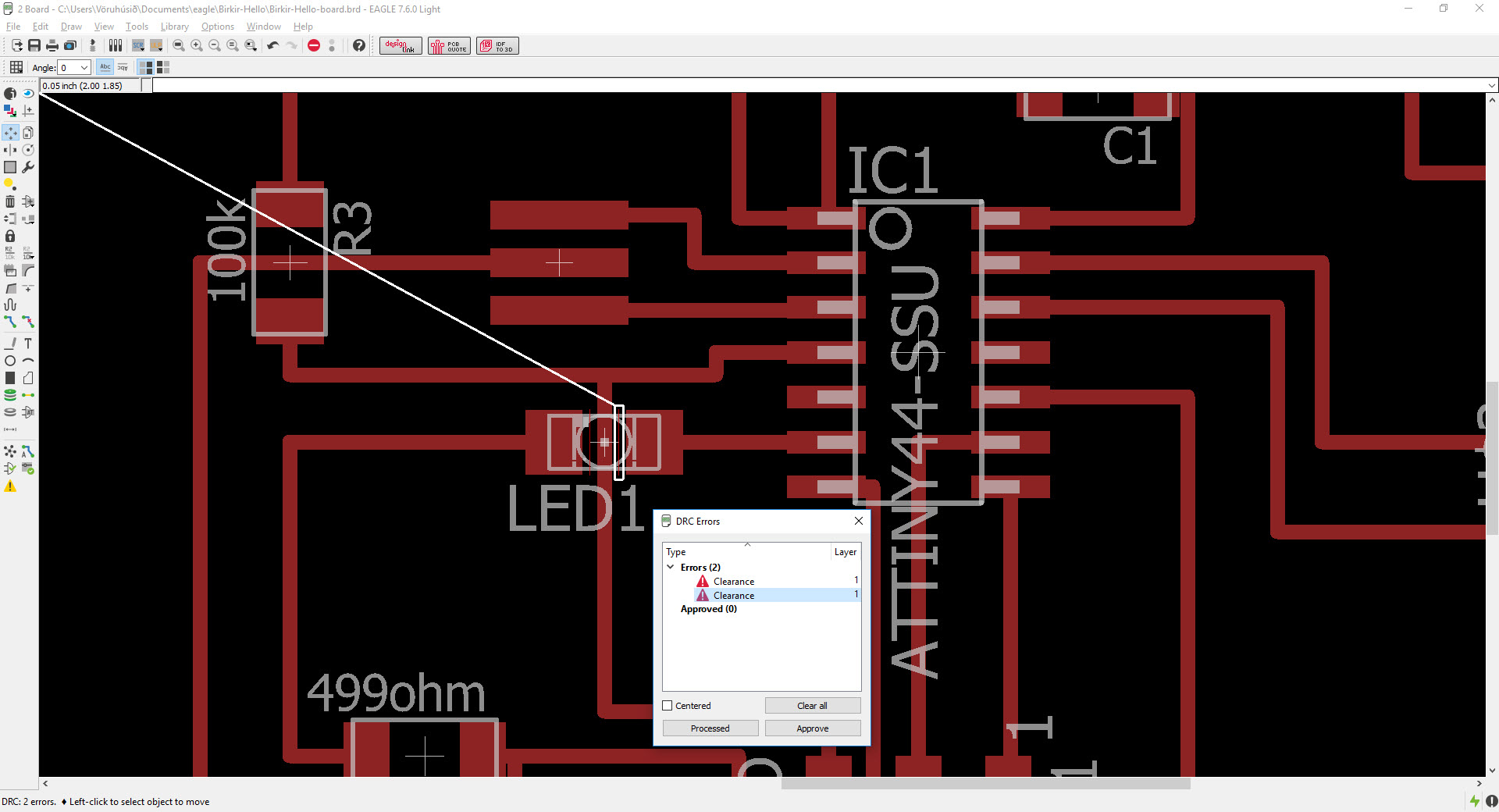
Then I ran a check and there were two errors. The distance between the LED and the trace underneath the LED was to close to each other. I clicked approve because I was going to fix it later in Photoshop. It's also possible to make thinner lines.
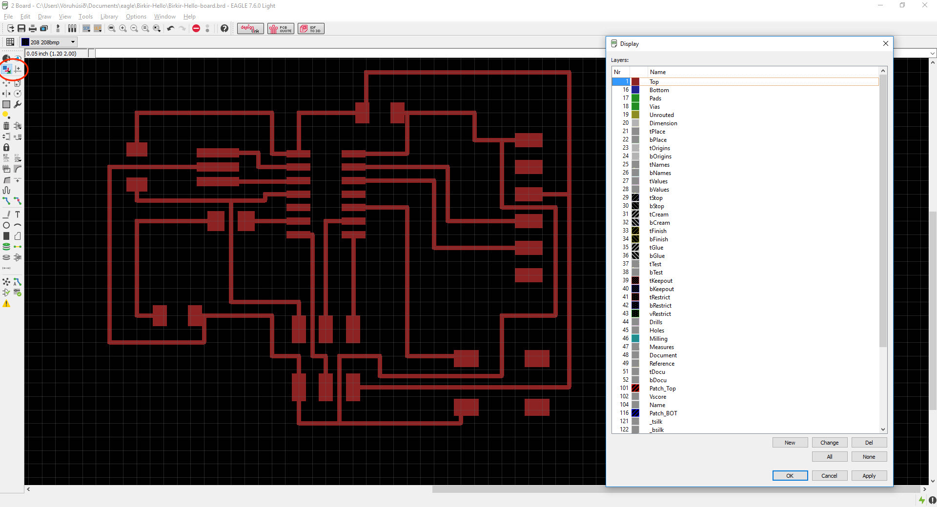
This is how the board looks like. All the traces are correct and everything is okay. Then I made the rectangle smaller (the white box which is outside the traces) and that would be the cut-out traces.
Then I opened the display window by clicking the layer window (in the red circleon the left) to have only the traces. First I clicked on none button and then I clicked the top which is number 1 on the top of the display window and clicked okay.
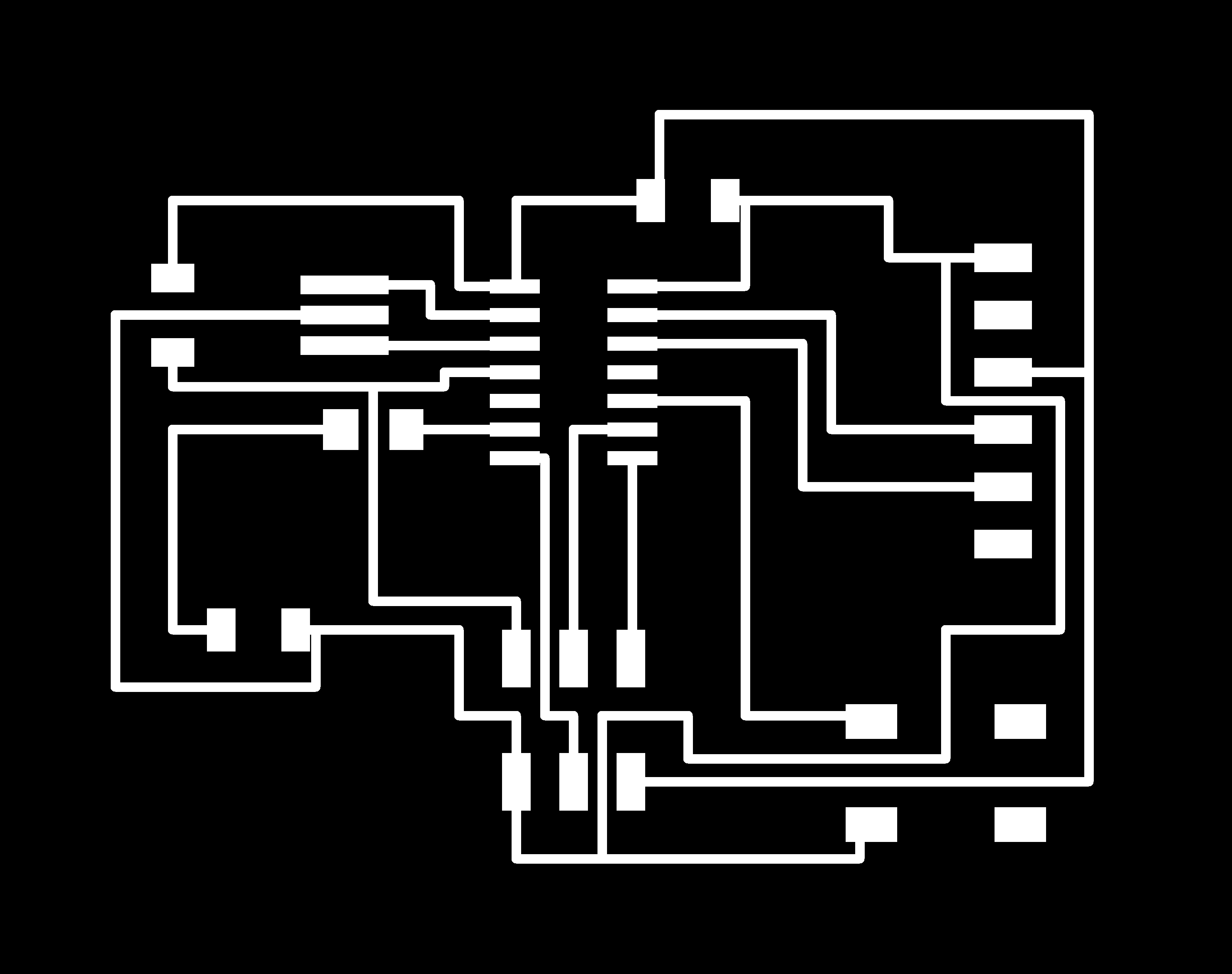
When it was ready I went to File --> Export --> Image and set the resolution to 1500 and put the monochrome on to have a black and white photo like the image below. I opened this image in Photoshop and cut a little part out from the LEDs so the space between would be more.
I went threw the same process with the cut-out process which was clicking on the layer button that opened the display window. I took the top (number 1) off and put on dimension (number 20) and clicked apply and okay. Then I exported it (same process as before). I used Photoshop to fill the black frame with white color. There is a little mistake in the left upper corner, I didn't see it on the board so it was okay. But the drawing of the echo hello-world board was ready for the next step.

MILLING THE BOARD
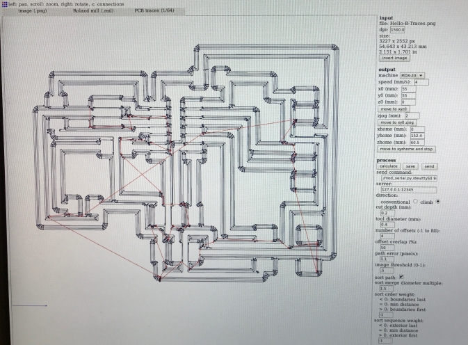
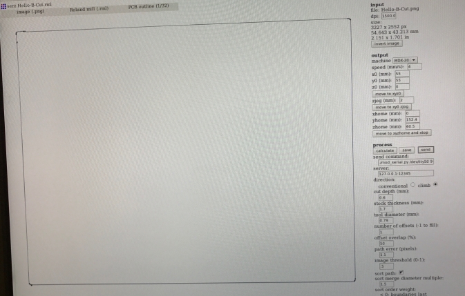
The process of milling the board was the same as in week 4. I went to fabmodules.org, insert the image, put Roland mil (.rml), PCB traces (1/64 inches), cut deepth 0.2 mm and calculated and everything was okay so I clicked send and it started milling the board. The milling machine in the lab is Roland MDX-20 Modela.
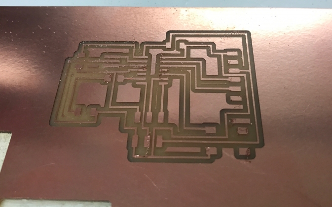
Then it looked like this. The drill was old so it had a few loose ends sticking up but it was easy to take of just by rubbing it a little.
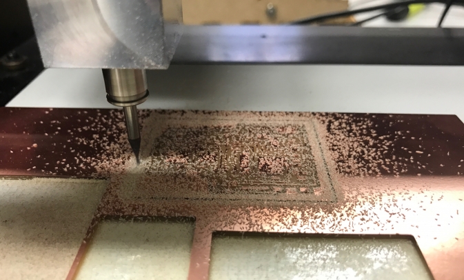
Then I did the same process for the cut-out image except the drill was 1/32 inches (I had to change the drill) and the cut depth 0,6 mm.
On the image below it is milling the cut-out.
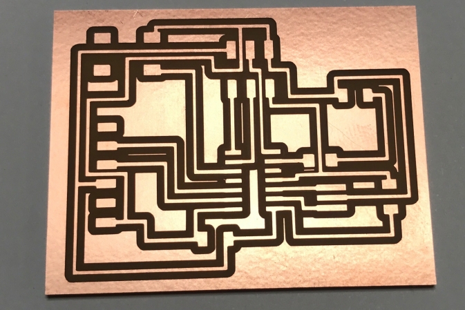
Then it was ready. I had to rubbed it to take the loose ends of and then clean it with water and let it dry. Even tough the drill was old everything was okay as you can see.
Then I collected all the components I needed and set it up like this and started soldering.
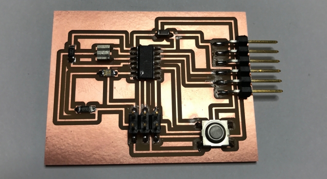
The soldering went well, better than last time and it is important to heat both the components so the tin will flow and spread over so it will be shiny. Like you can see on the image below I forgot to solder the pin on the bottom to the left on the ATtiny 44. Also I found out that I had to reverse the LED.
TESTING THE BOARD
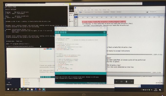
I wanted to test the board to make sure it was okay. I started programming it in a command window but there was an error in step two. I was running out of time so I decided to test the board with Arduino instead. There will be more about this project in the Embedded programming Week (week 8).
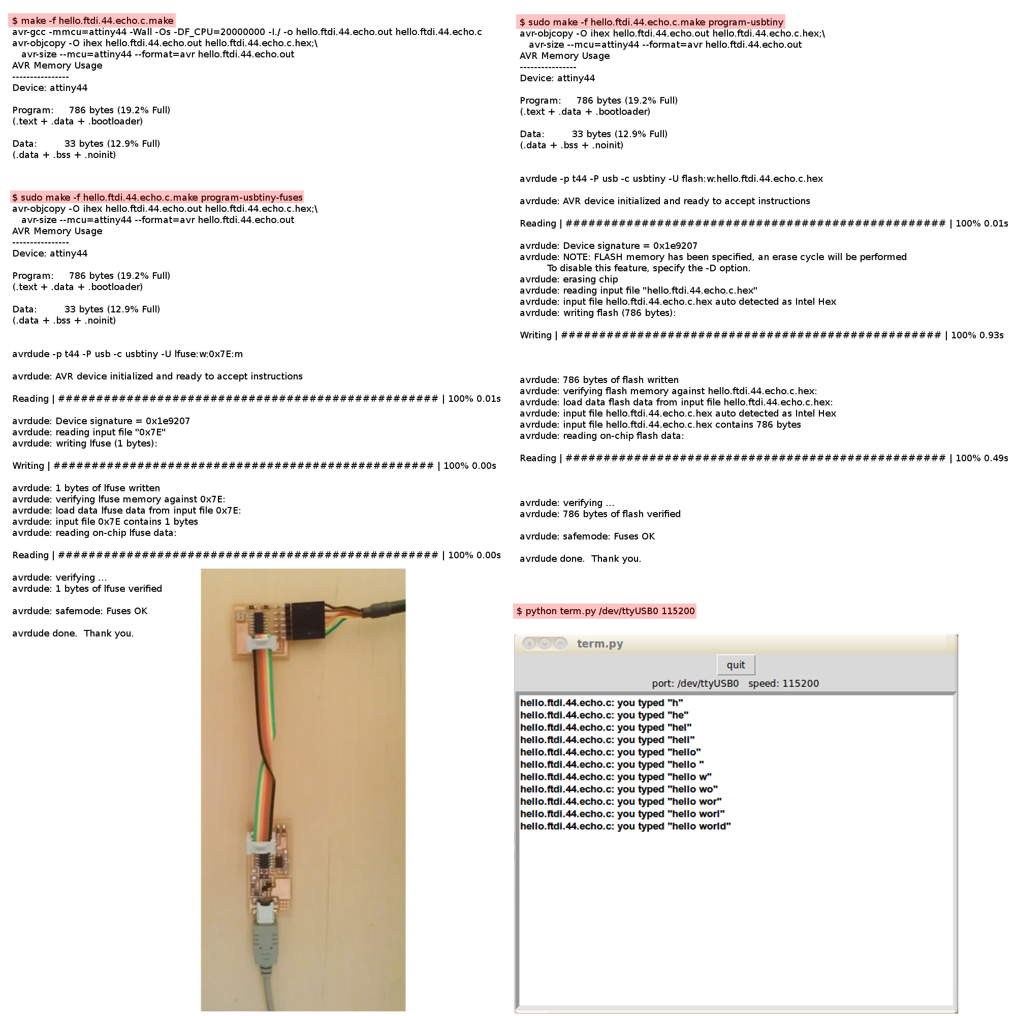
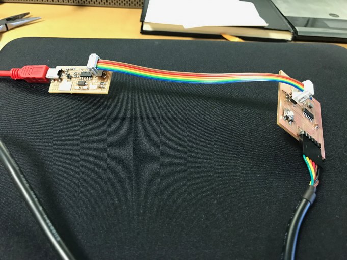
I connected the two circuit boards (the one I made in week 4 and now).
I used a code on Arduino to turn on and off the LED. It was then when I realised that I had to reverse the LED and to fix a soldering on one of the ATtiny 44 pins. After I did that it worked.
RELATED LINKS
DOWNLOAD FILES
Echo Hello-World Board Traces - Right click to download
Echo Hello-World Board Interior - Right click to download
Echo Hello-World Board Schematic - Right click to download
Echo Hello-World Board brd - Right click to download
HAVE QUESTIONS?
Contact me!
Höfn, Iceland
Email: birkirthorhauksson@gmail.com
Swing by for a cup of , or send me a message :)