WEEK 7 - COMPUTER-CONTROLLED MACHINING
ASSIGNMENT
- Make something big
DESIGN
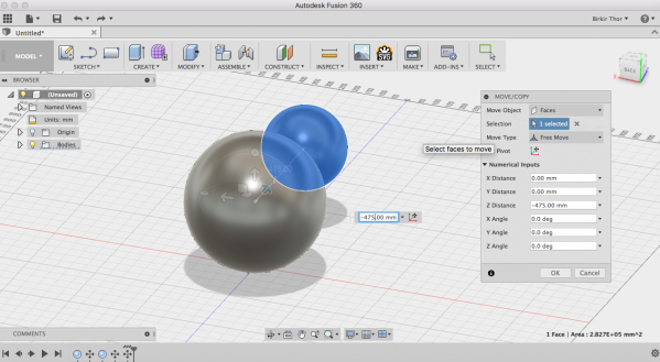
This week I decided to make a sphere that I would slice down so I could put it in a light pulp and it would shine through. I started by making two spheres with the radius 250 mm and 150 mm.

Then I clicked m to move it. I moved it in the middle inside the bigger sphere.
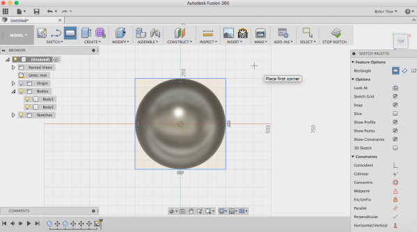
I drew a 250x250 mm rectangle on the bottom and extruded it up to 150 mm and subtract it from the spheres. To extrude I clicked e.
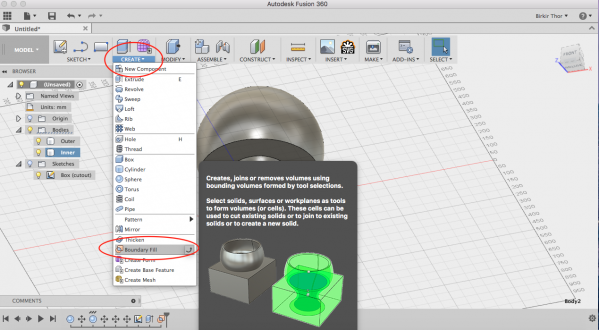
Then I cutted the smaller sphere from the bigger one by going to create and boundary fill (see in the red circles) to do that.
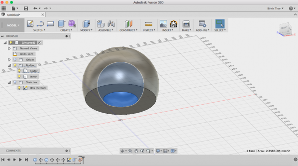
Here you can see how it looks like after I removed the inner sphere. Then I saved it as a stl file and it was ready for next step.
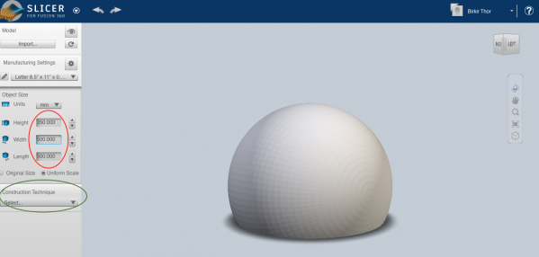
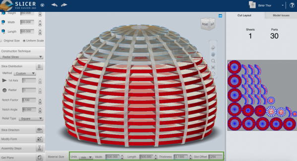
I decided to slice the sphere down so I used Slicer from Autodesk. I imported the stl file and put the width and lenght to 500 mm and the height would be 350 mm. Then I went to construction technique and select the radial slices so it would slices from the middle (see in the green circle).
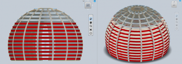
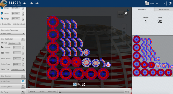
Then it looked like this. I decided to have 30 parts (15 and 15).
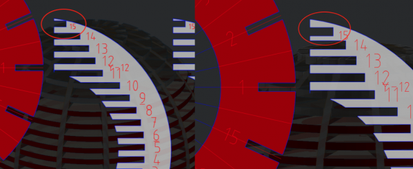
Part number 15 (see in the red circle) was to thin so I lowered the top disc so the thin part wouldn't break off. I also lowered the second disc to even out the distance between them.
To move an object I went to modify form (see in the red circle) and selected the part I wanted to move.
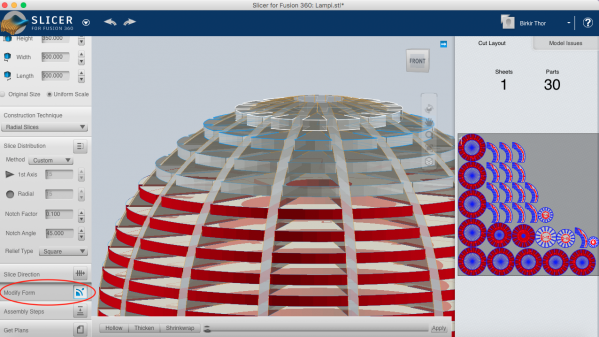
The Slicer software cuts objects in flat units compare to the thickness of selected material. I can decide the size of the page and export this as pdf file. There are 30 parts on one sheet there but I will have them on more than one. The reason why most of the parts are red is because it's showing errors. To see the errors I went to model issues and it said notch intersects hole, but it supposed to be holes on those parts so it didn't matter.
Then I went to manufacturing settings to put the size of the materials. I put the width and the length to 2500 mm to have it all on the same page. Then I put the thickness to 12.150 mm and the slot offset to 0.254 mm. Then I saved it as a pdf and opened it in Inkscape.
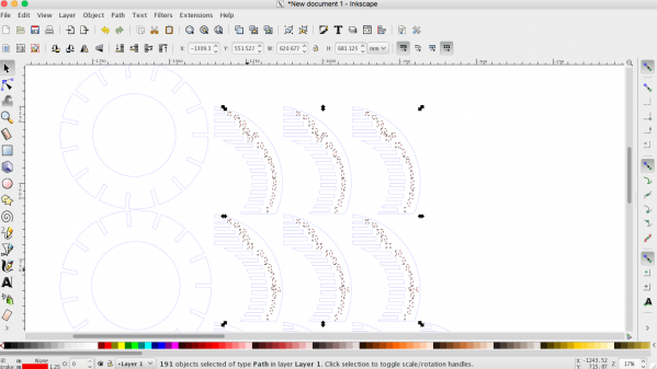
I imported the pdf file in Inkscape and took all the numbers away, I only needed the outlines. First I had to select everything and ungroup and break apart so I could delete the things I wanted to.
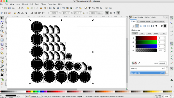
Then I took the stroke off and put fill on. Because I couldn't put all the parts on one plate so I had to make two files. So I went to File --> Document Properties --> Custom Size and put the page size the same size of the plate I was going to use.
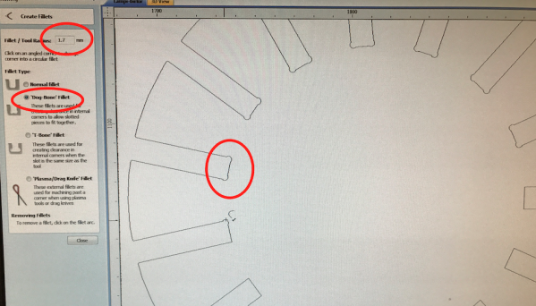
First I needed to make a test before I would mill everything. I imported the pdf file into VCarve Pro and put a Dog Bone Fillet on every inner part (because the milling bit won't do 90° corners so small). You can put Dog Bone Fillet in Slicer for Fusion 360 but I forgot to try that out, so I did it like this. I also put two pins on each part so it would keep still while milling. I had also added some pins that would holed the object still. I was going to use End Mill 1/8.
For this project I decided to use plywood because I needed a lot of it and it's not that expensive. The machine I used to mill it was the Shopbot. When it was finished I took the pins off with a hammer.
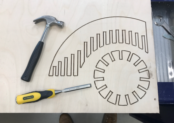
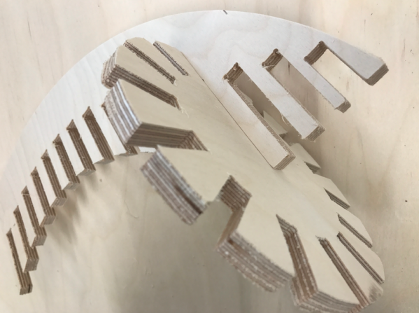
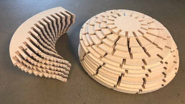
Then I sanded the parts a little and put them togheter and it fit perfectly. So the next step was to make the other parts.
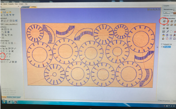
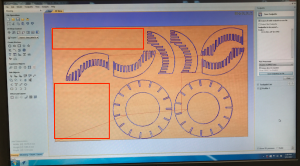
I started by importing the pdf file into VCarve Pro and put the size of the length, height and the thickness of the plate. Then I arranged all the parts so they wouldn't touch each other or be outside the plate. Then I made Dog Bone Filled on every inner part like before and but two taps on every part so they would stay still. Some parts were not fully closed so I clicked on the button in the red circle on the left to close them so I could continue. Then I clicked on the button in the red circle to the right and put the cut dept to 12.15 mm and calculated.
On the left image you can see that it was really close to another cut out but it was okay. On the right image the drill broke because the plate was little curved. So I put a new drill inside and kept on milling the lamp shade.
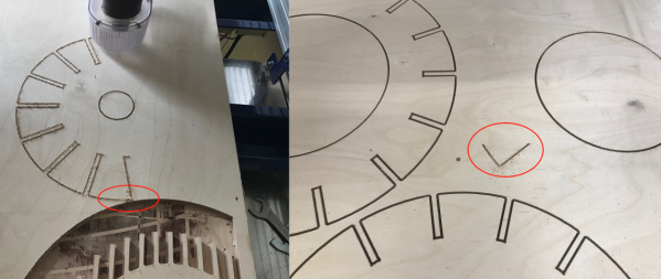
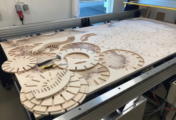
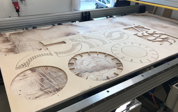
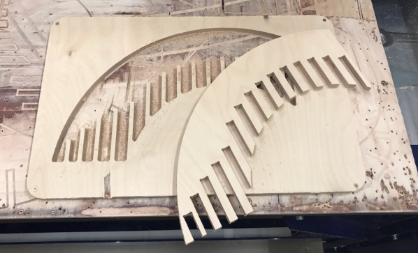
Then when it was ready I took all the parts out.
I could not mill where the red boxes are, because the plywood had been used before.
Everything went alright. While the parts were being milled I sanded those who were ready.
I had three parts left and three 12 mm plates to use. So I made three parts like on the image below than it was all done.
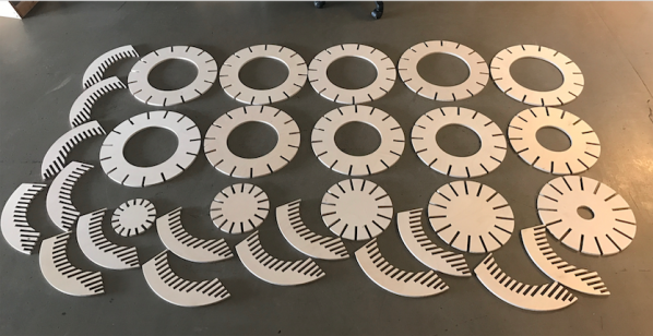
Than I sanded all the 30 parts, it was difficult and took a long time. The parts on the image on the left were leftovers and I will definitely use them later to make something out of it.
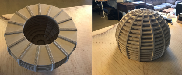
When I had finally sanded all the parts it was ready to be combined.
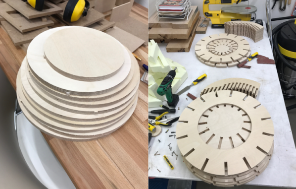
Then I put it all together. I started putting it together alone and it was really difficult so I called my cousin to help me and it was much easier. I started putting all the discs on one part (image on the left) and then put one by one which is harder than it looks like.
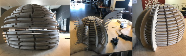
Then it was ready. It´s really heavy because I used a lot of wood.
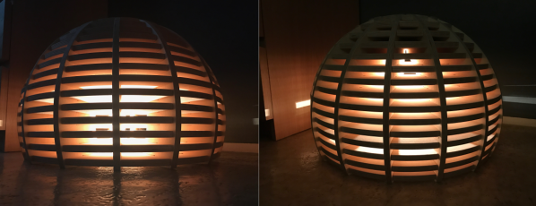
Then I put a light bulb in it so it would light up the sphere. It looks really nice when it is dark. Maybe later I will put LED lights.

WHAT DID I LEARN?
This week I learned how to work in the software Slicer and using the Shopbot.
RELATED LINKS
Slicer for Fusion 360
VCarve Pro
Shopbot
DOWNLOAD FILES
Ball Slicer for Fusion 360 - Right click to download
Ball Inkscape - Right click to download
Ball PDF - Right click to download
Ball STL - Right click to download
Ball VCarve Pro I- Right click to download
Ball VCarve Pro II - Right click to download
HAVE QUESTIONS?
Contact me!
Höfn, Iceland
Email: birkirthorhauksson@gmail.com
Swing by for a cup of , or send me a message :)