WEEK 10 - OUTPUT DEVICES
ASSIGNMENT
- Add an output device to a microcontroller board you've designed and program it to do something
MAKING THE HELLO RGB 45 CAD BOARD
This week I was going to make a board with a RGB LED light. The goal is to have a few RGB LED lights in my final project and use a RGB LED board in my machine kit to paint with light, so this week will be ideal for that. RGB means red, blue and green LEDs. RGB LED products combine these three colours to produce numbers of hues of lights.
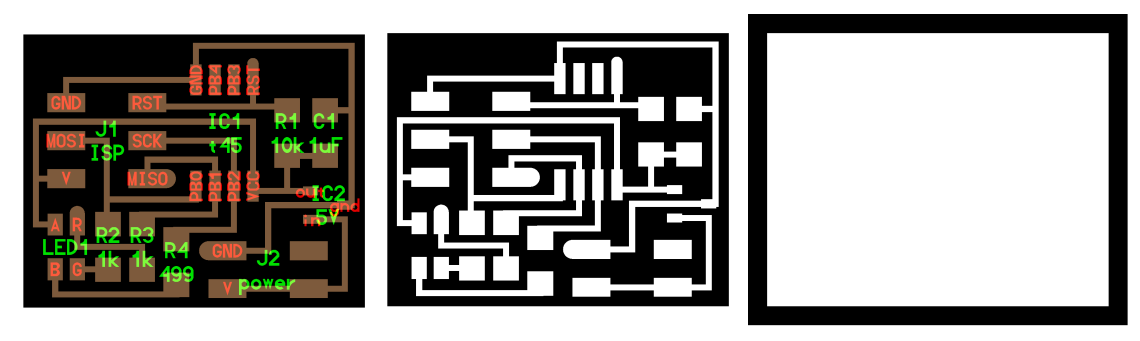
I didn't have a lot of time this week but I managed to do something. I started making the HELLO RGB 45 CAD BOARD. I took the traces and cut files here, it's under the RGB LED.
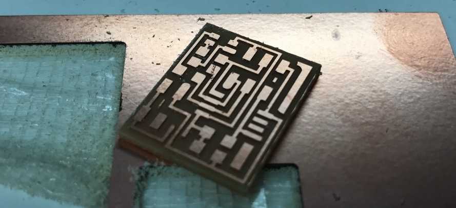
I milled the board with the Roland MDX-20 and everything went well. For more details you can see the milling process in week 4.
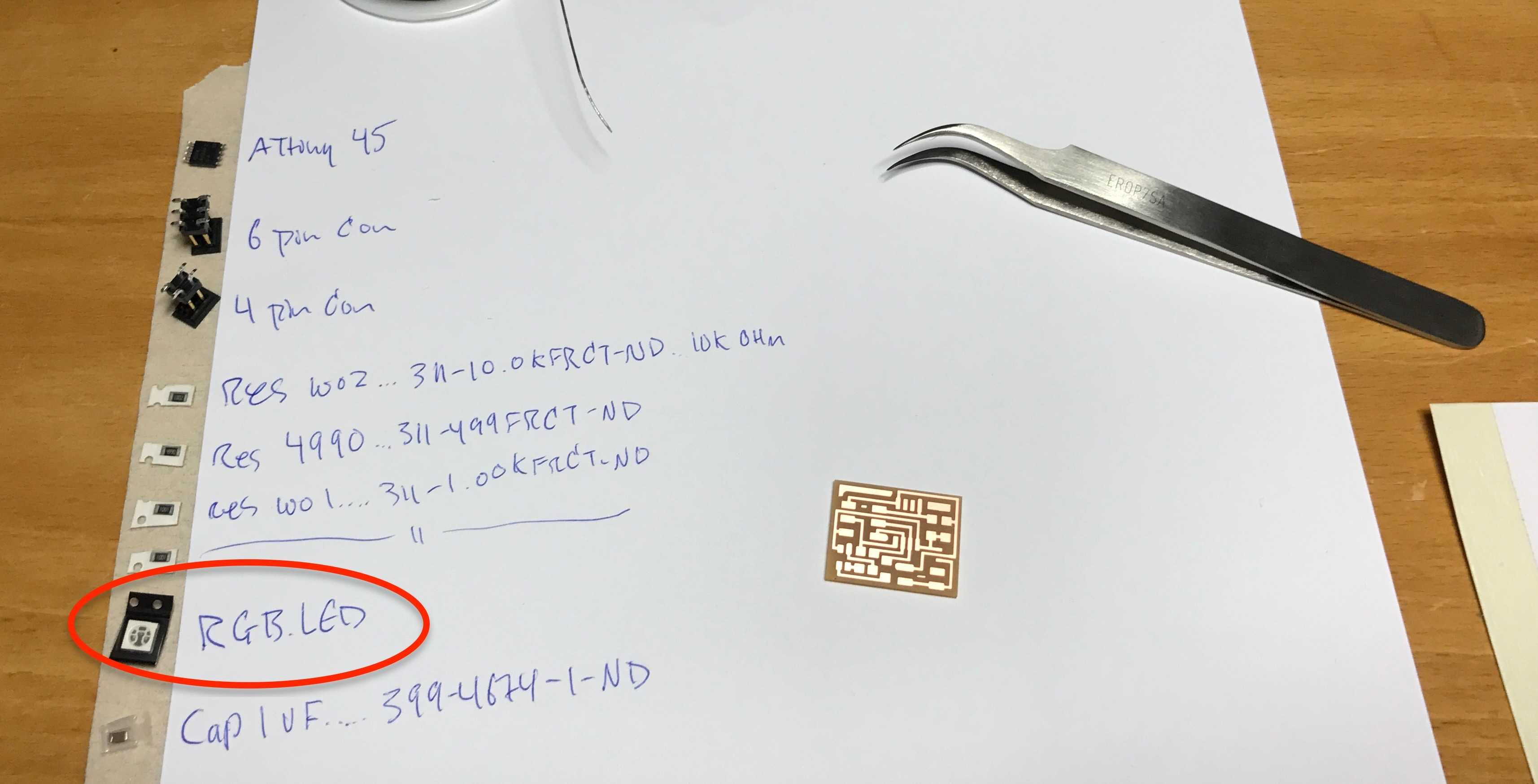
Then I collected all the components and it was then when I realised when I had the wrong RGB LED.
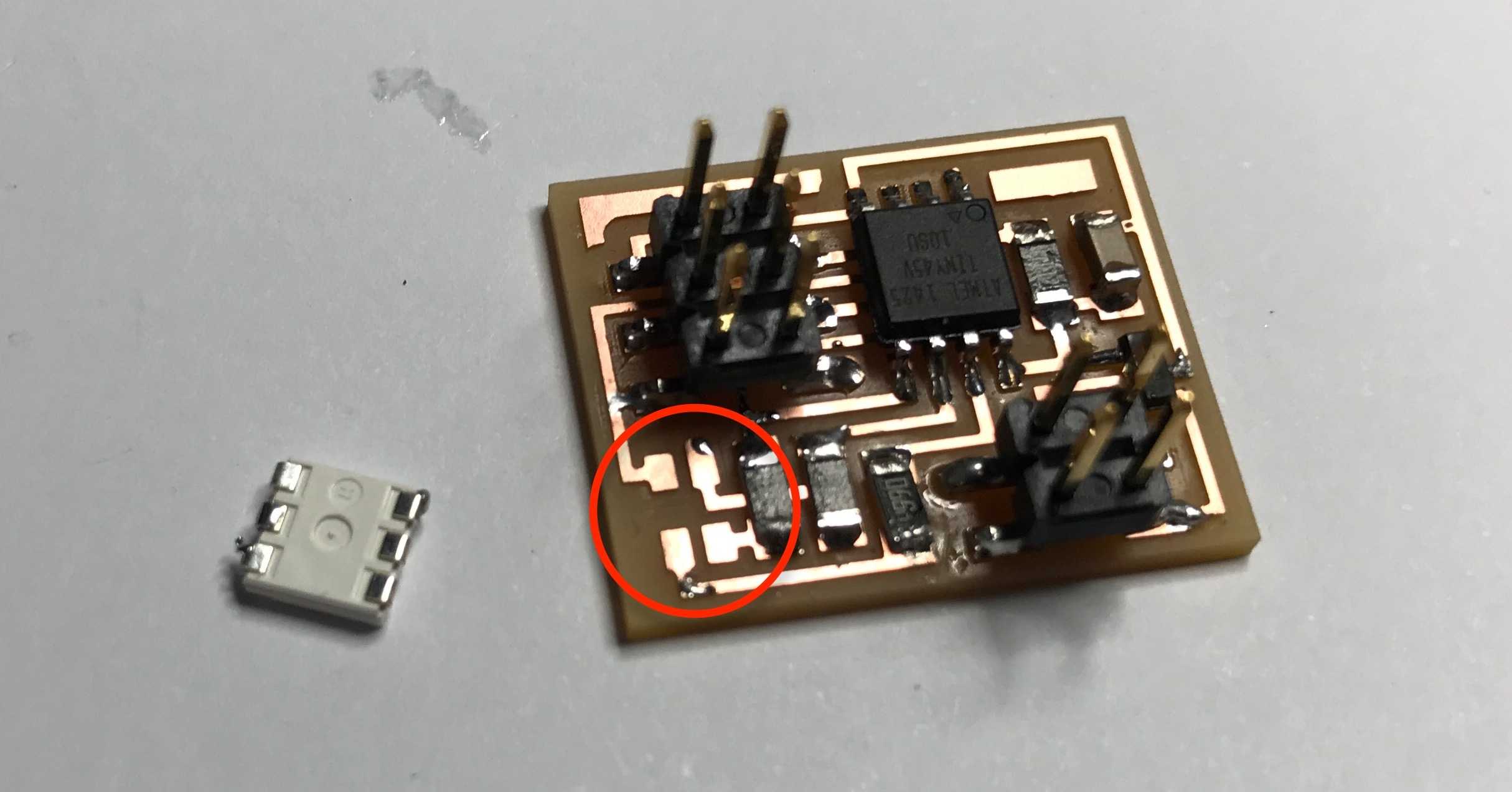
Despite having the wrong LED for this board I soldered it anyways just in case I would get the four pin RGB LED later. You can see on the image below that there are six pins on the RGB LED and only four on the board.
DESIGNING MY RGB BOARD
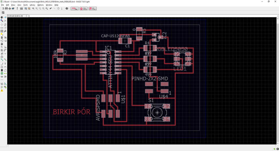
Then I designed my own RGB board. I used Eagle to do that. You can see more details in week 6 how to make your own board. It's the same proccess just different components. This board is powered with a 9 V battery and has one RGB LED and one button.
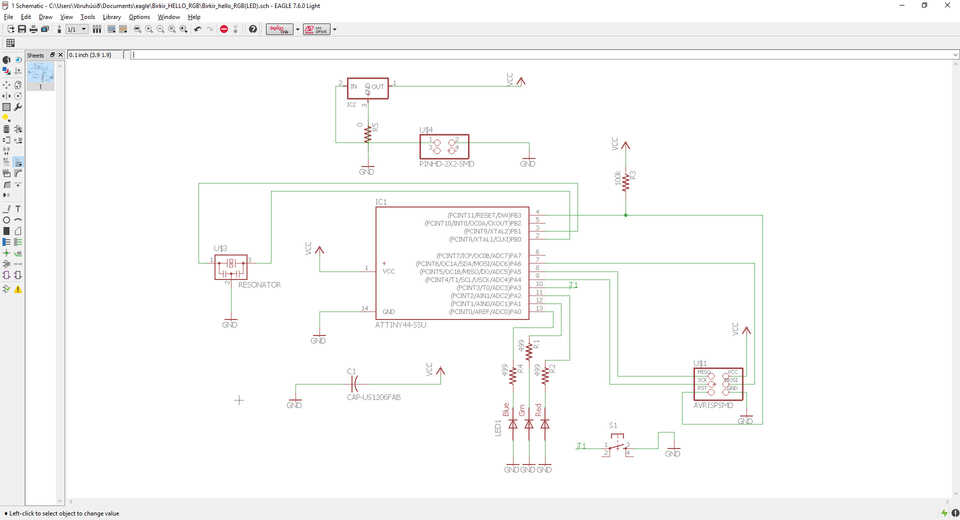
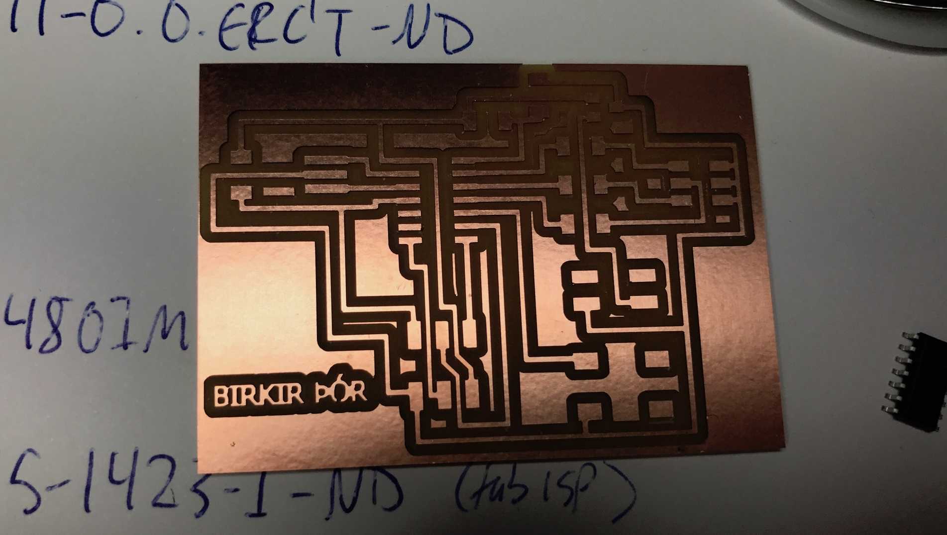
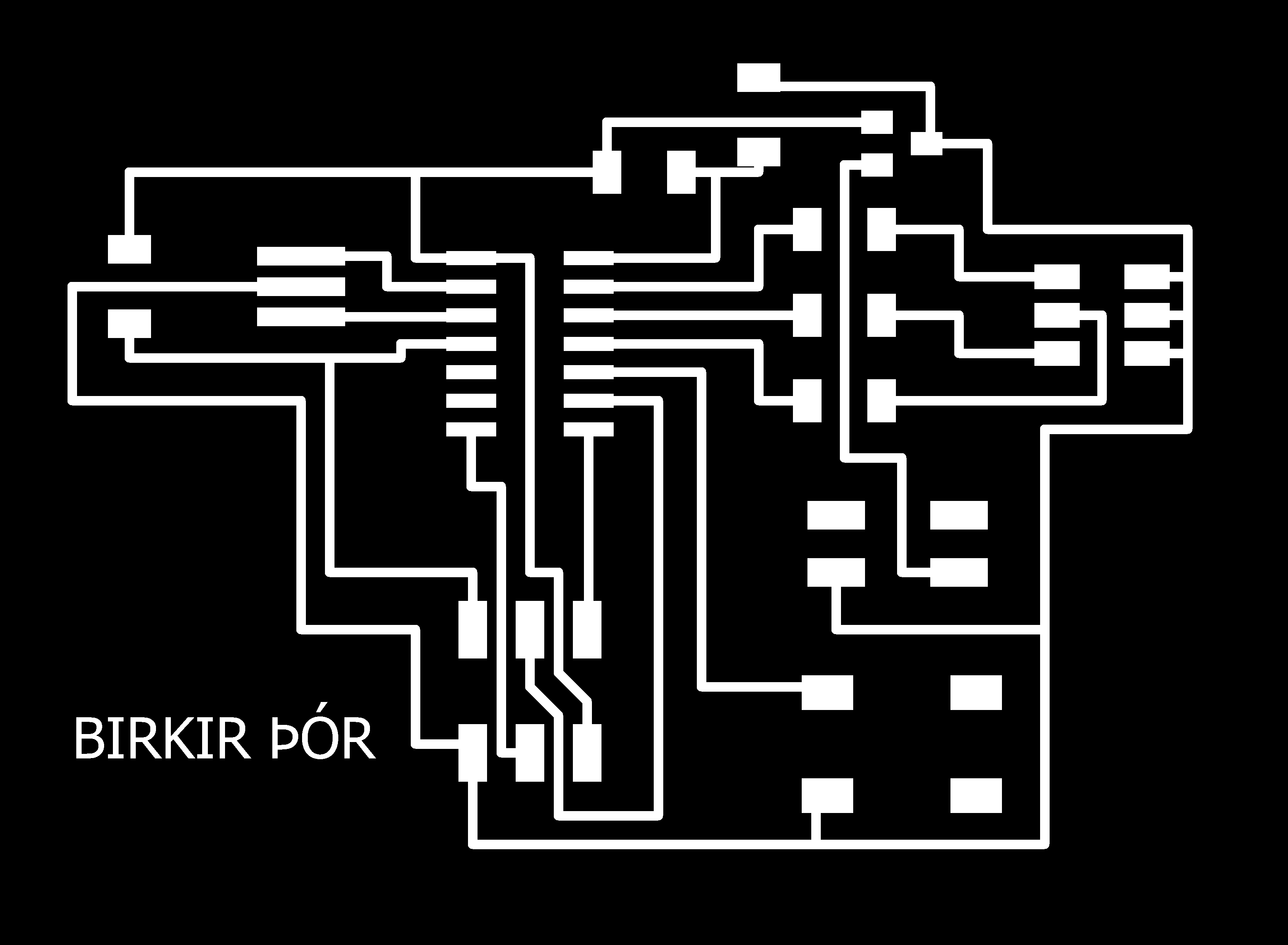
When I had slected all the components I conected them. I added a zero resistor to jump over one line. Then I wrote my name on the board just for fun. There were no errors so I exported the traces and cut file as PNG.
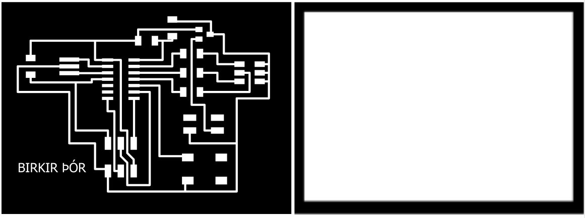
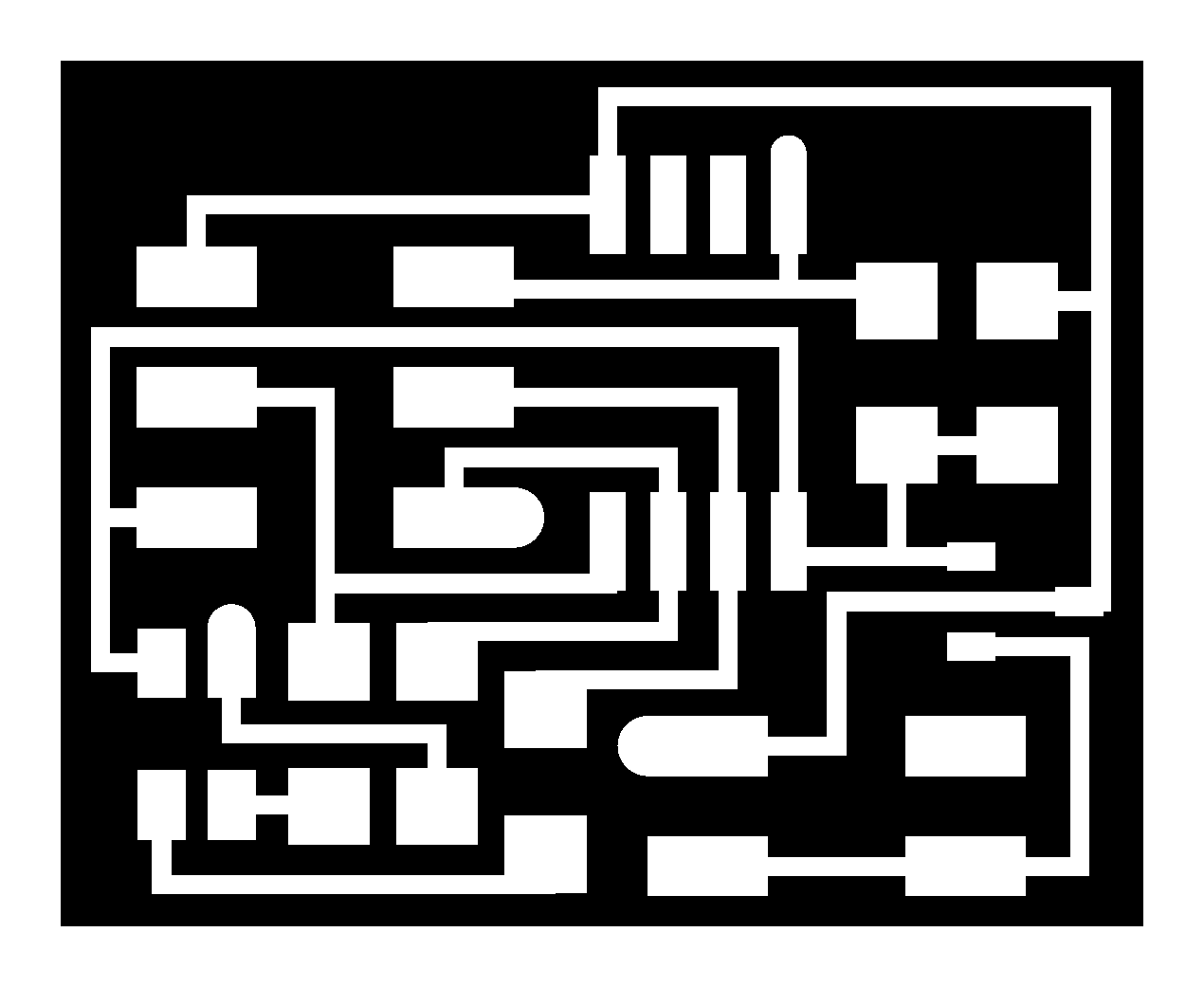
These are the trace-and cut PNG files. Ready to be milled. You can download them at the bottom of this page in Download Files.
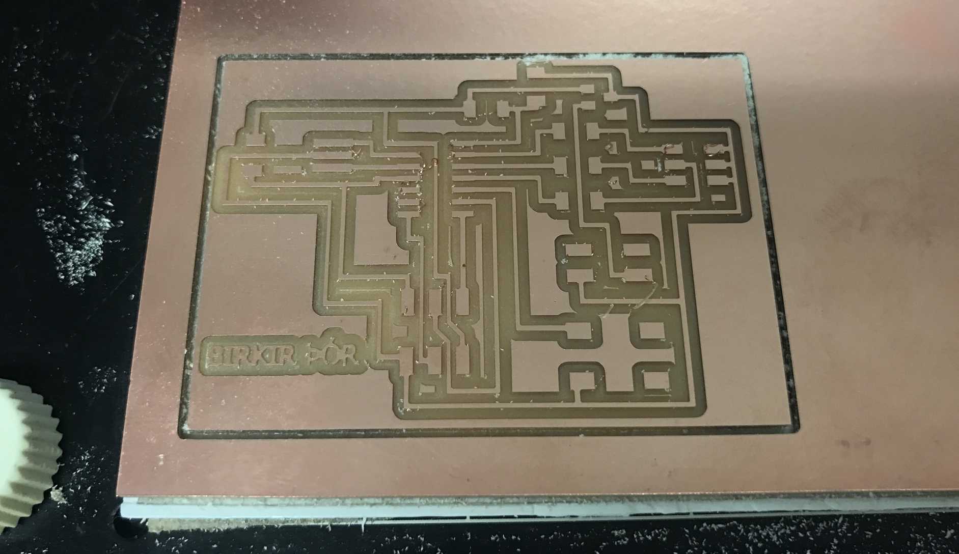
I used 1/32 for the traces and 1/64 for the cut. Everything went well so I took it off and cleaned it with water.
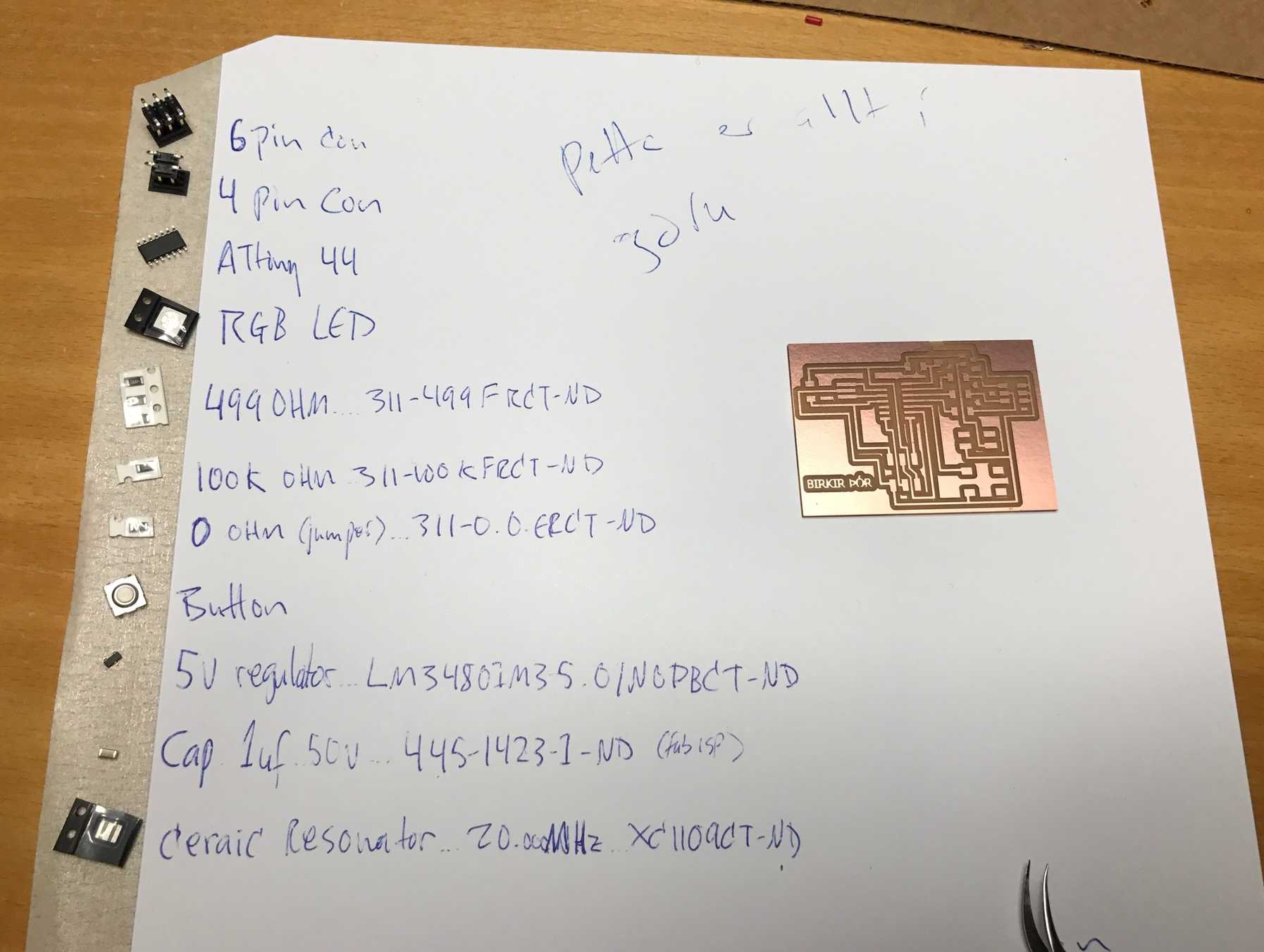
Those are all the components for the board.
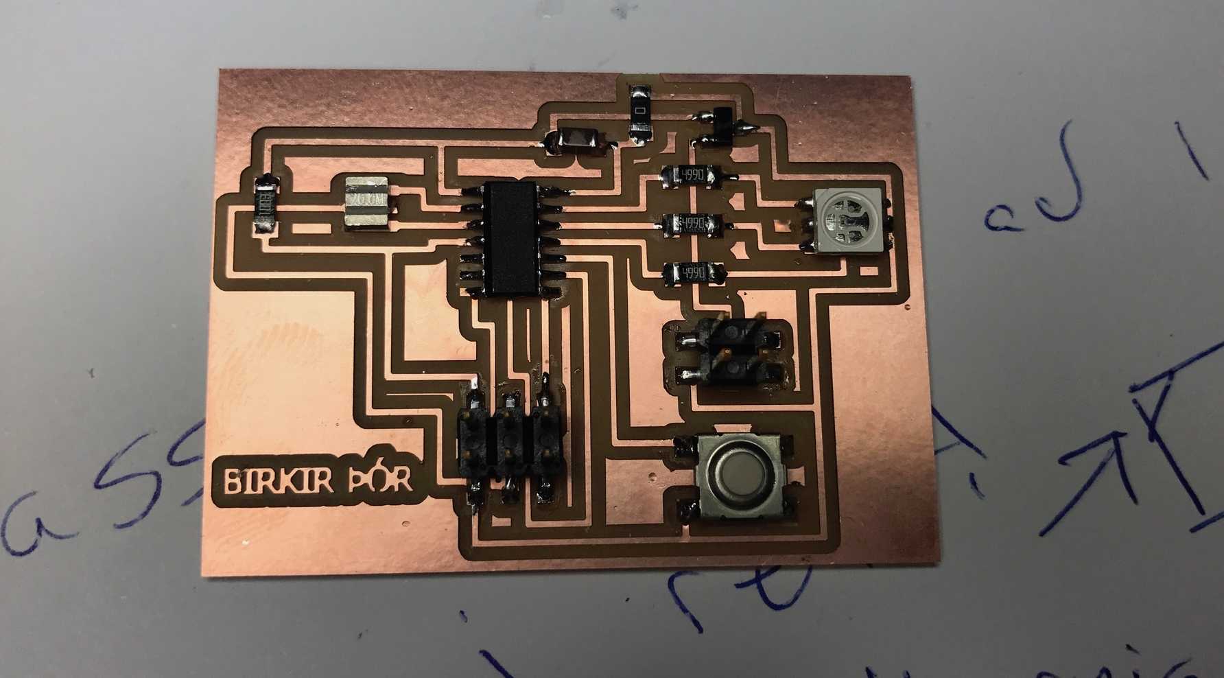
The two images below are before and after soldering.
Everything went well. I'm getting better at soldering everytime.
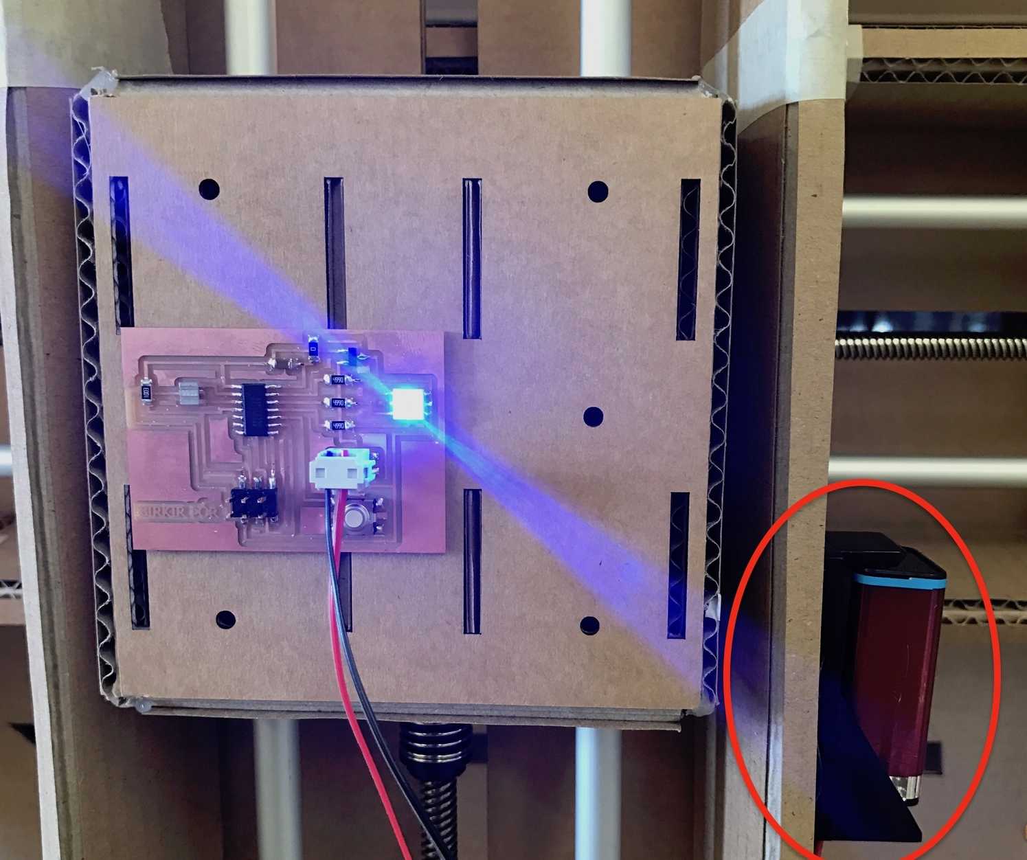
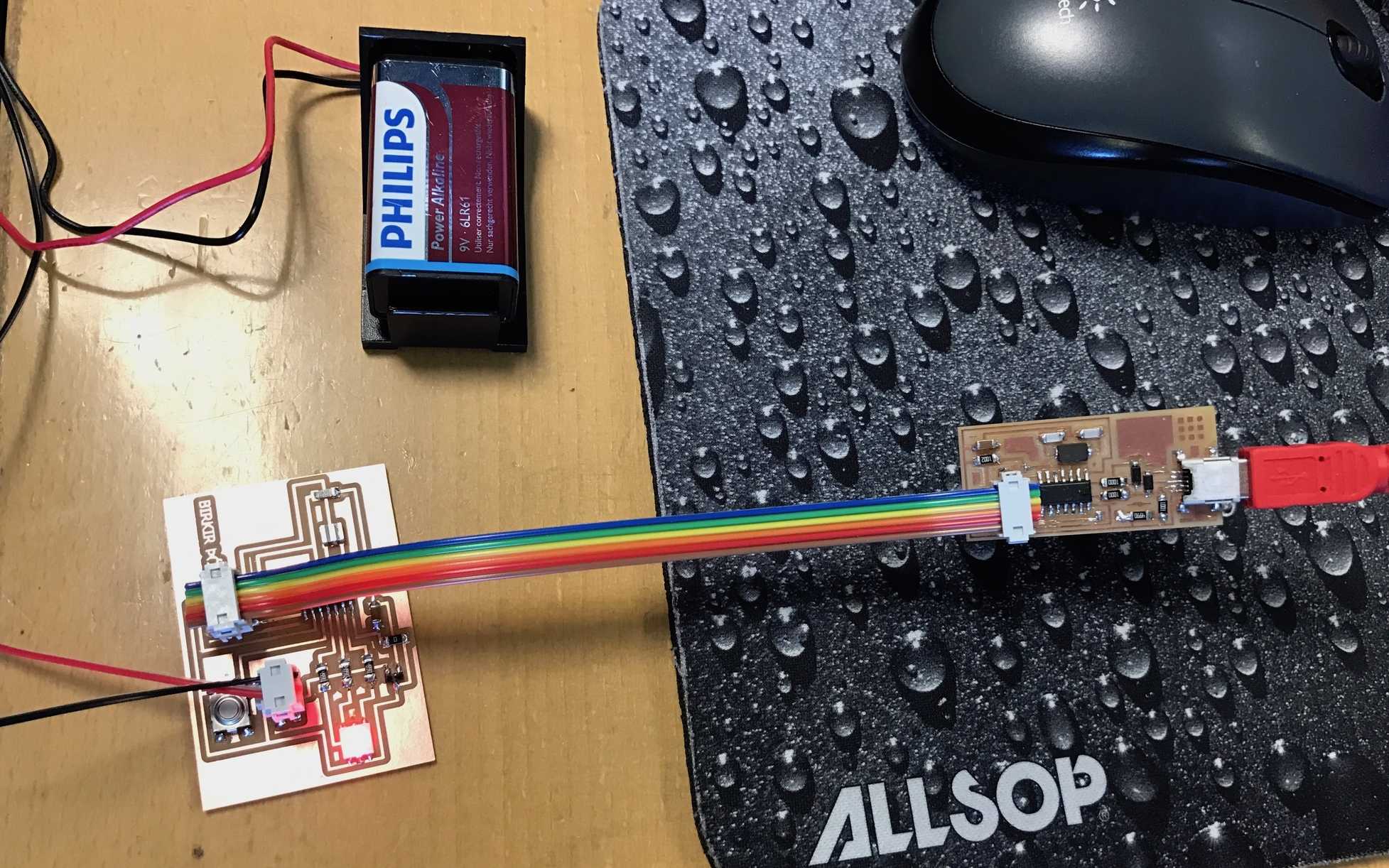
Then I plugged the board with the FabISP programmer and a battery and programmed it. Everything was okay, which was good because I did this on the last day of the week. I taped the board and the battery on the machine kit.
PROGRAMMING THE BOARD
This is how the boards should be connected. The board is power with 9V battery. The programmer can be unplugged when the board is programmed.
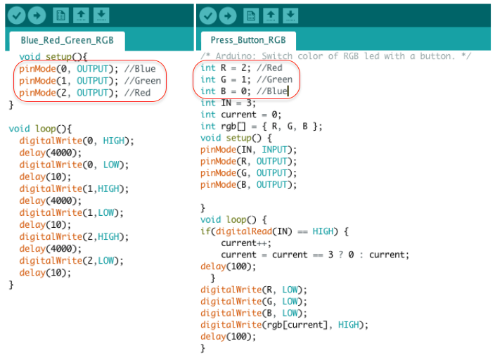
I decided to program the board with Arduino because I'm familiar with it. I downloaded some arduino codes to play with and changed them a little just for fun. You can download them in Download Files below. I had to change the pins which you can see in the red circles. The image below shows two different arduino codes. You can see the pin configuration in week 8 on the first two images.
VIDEO
This is a video of the board I made with the Arduino code running through some colors.
RGB_video from BirkirThor on Vimeo.
Here is another Arduino code. There is some conduction problem, when I touch press the button it changes colors like it should be, but when I touch a pin on the board it also changes colors.
RGB_video2 from BirkirThor on Vimeo.
RELATED LINKS
Hello RGB LED Board
week 4
week 6
week 8
DOWNLOAD FILES
Hello RGB 45 Traces - Right click to download
Hello RGB 45 Interior- Right click to download
Birkir RGB Board Traces Birkir - Right click to download
Birkir RGB Board Interior - Right click to download
Echo Hello-World Board brd - Right click to download
Arduino codes:
Blue Red Green - Right click to download
Fast RGB Button - Right click to download
Press Button- Right click to download
HAVE QUESTIONS?
Contact me!
Höfn, Iceland
Email: birkirthorhauksson@gmail.com
Swing by for a cup of , or send me a message :)