WEEK 19 - PROJECT DEVELOPMENT
ASSIGNMENT
-
Complete your final project, tracking your progress:
- What tasks have been completed, and what tasks remain?
- What has worked? What hasn't?
- What questions need to be resolved?
- What will happen when?
- What have you learned?
GUITAR KIT AND DESIGNING
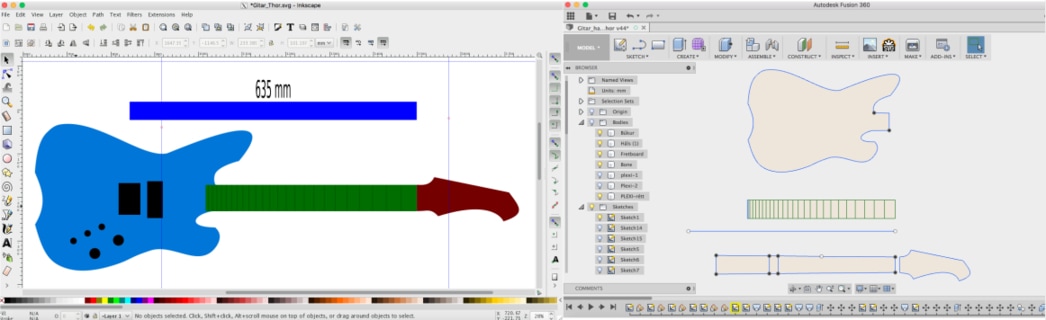
I wanted to make an electric guitar, so the first thing I did was to find a scale length. I went to Stewmac.com and found a list of common scale lengths. I decided to go with the Paul Reed Smith, 24 frets and scale length 635 mm (25"), which you can see on the bottom of the image below. On Stewmac they explain the scale lenght as:
A guitar's scale length is calculated by measuring the distance from the front edge of the nut, where it butts against the end of the fingerboard, to the center of the 12th (octave) fret, then doubling that measurement.
Then I used the Fret Calculator on Stewmac to calculate the fret position, which is the image to the right.

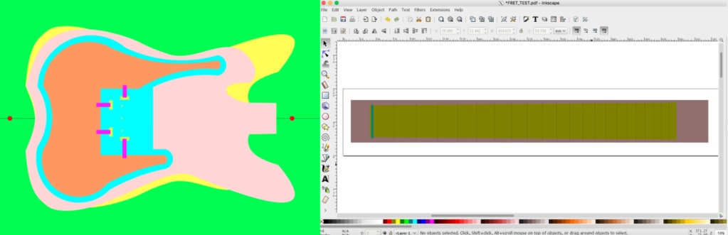
Then I used Inkscape to draw the frets in right proportions. I wrote the numbers I got from the fret position calculator and set the guidelines where each fret is located.

I also designed a guitar body and headstock in Inkscape and put them together to get some idea what I was going to do. You can see the scale length above the guitar, 635 mm. Then I saved the file as SVG and opened it in Fusion 360. I had to unlock the lines or else I couldn't move them. I changed the shapes and improved them.
DESIGN THE GUITAR
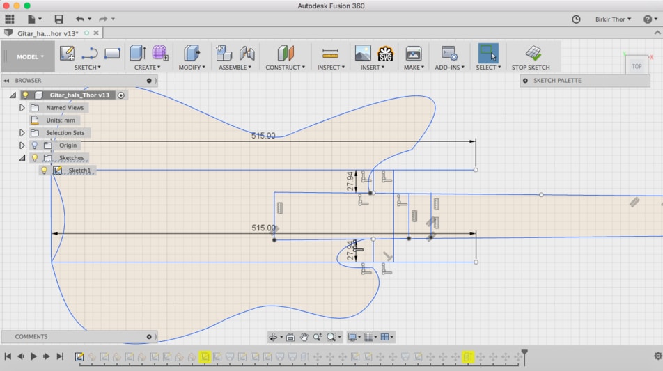
I changed some lines so the guitar would look better and center the neck and the body.
Then I drew the neck in 2D and made curves on selected places and used loft command to make a 3D body.
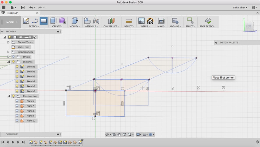
Then I extruded the body up to 42 mm which is the thickness. I used loft command to join the lower part of the neck to the upper part. I rotated the the headstock about 6 degrees and joined the neck and the headstock with a loft command. Then I made a neck pocket by difference the neck from the guitar shape.
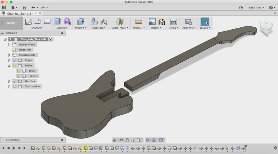
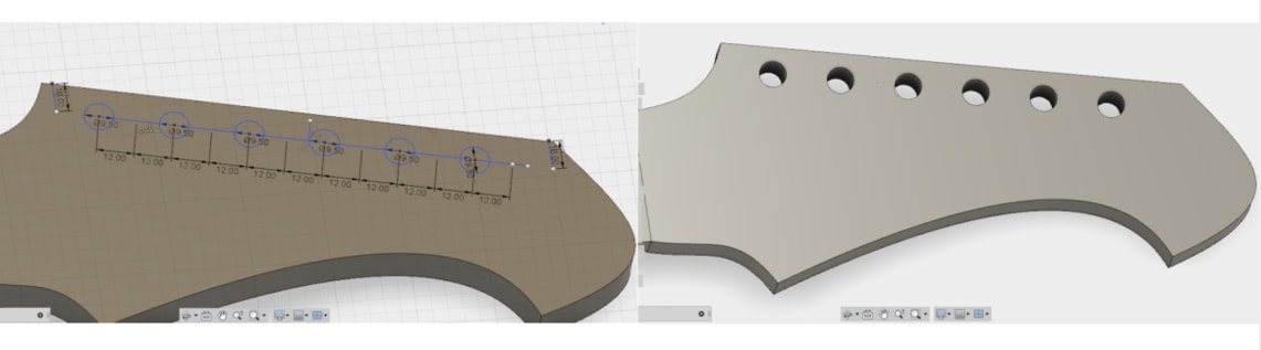
I made holes for the tuning machines, but the ShopBot was not going to mill them because the headstock had 6 degree incline, it was more just to measure the lengths that I would later drill manually.
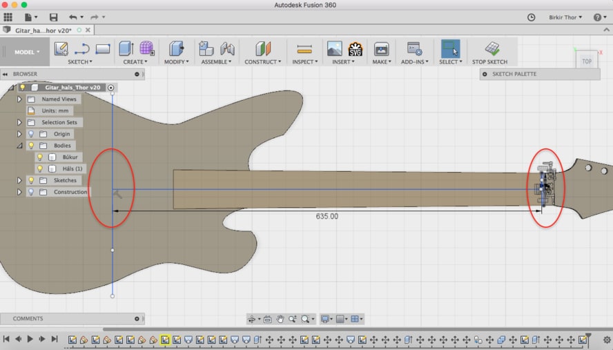
This is the scale length, 635 mm. On Stewmac they explain the scale length as:
A guitar's scale length is calculated by measuring the distance from the front edge of the nut, where it butts against the end of the fingerboard, to the center of the 12th (octave) fret, then doubling that measurement.
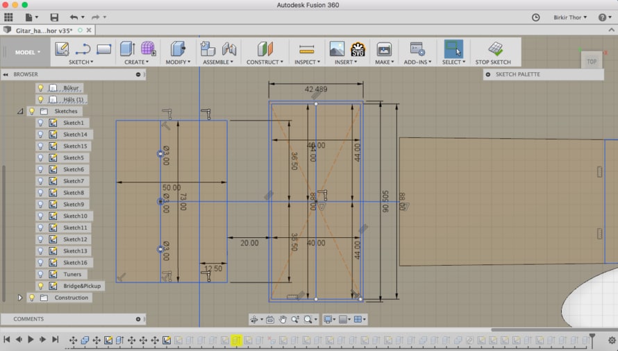
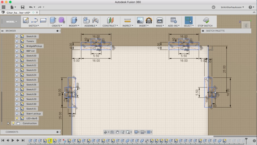
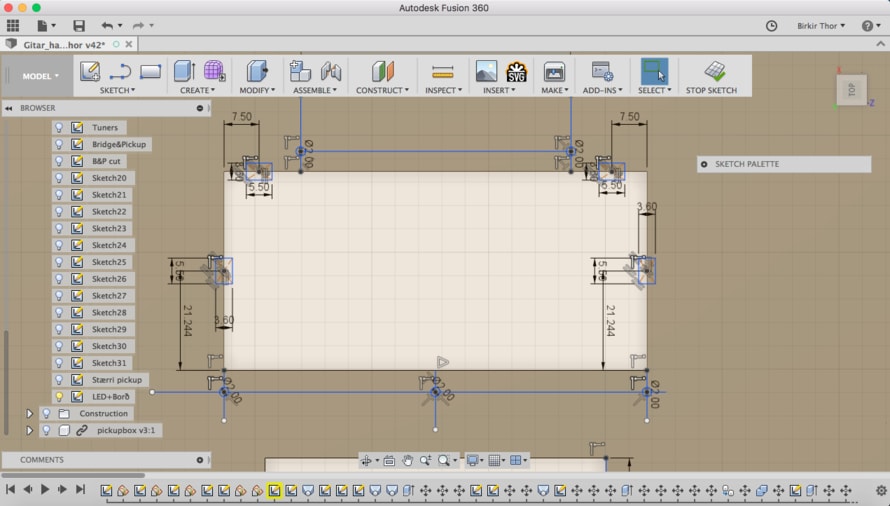
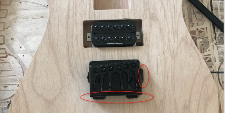
Those are the measurements for the pickuphole and the bridge location for the screws, compare to the center of the neck.
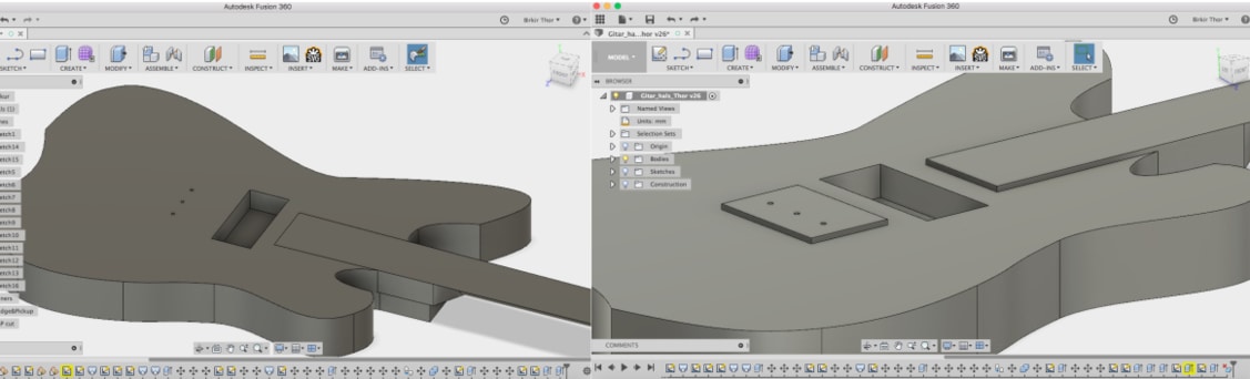
On the image to the right I lowered the body down to 3 mm so the plexiglass wouldn't be too close the strings.
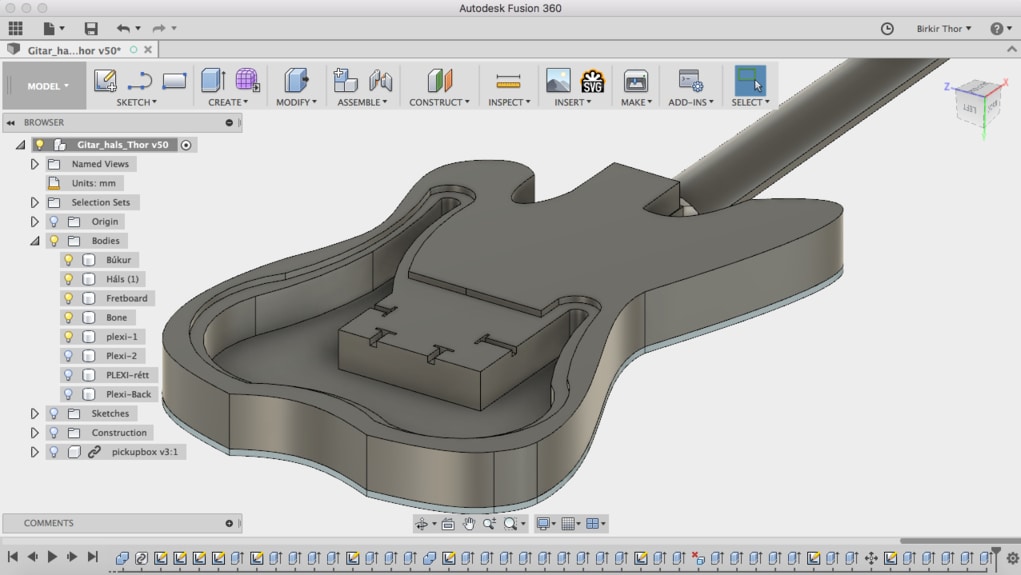
Here I'm making the bone, to see the distance between the guitar itself and the strings. I made the nut by creating a box and extrude it down and cut it. Then I extrude it up as a new component.
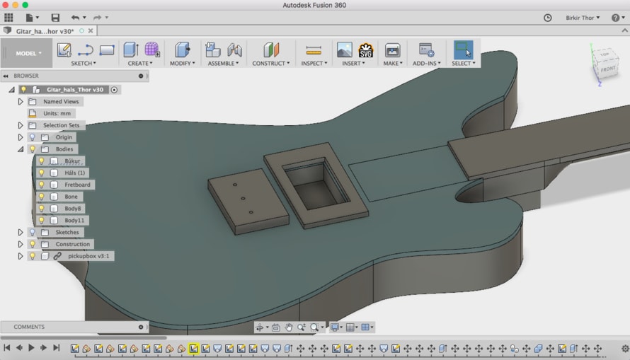
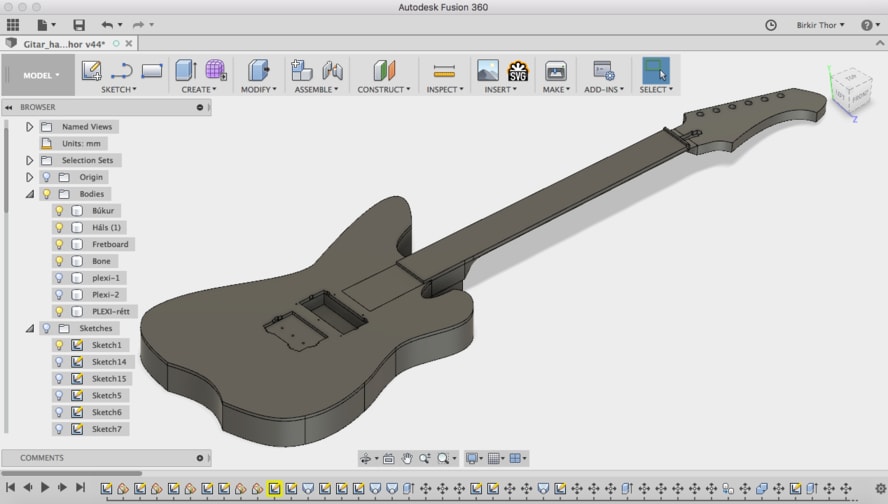
This is how the guitar would look like with the bridge, pickup, pickup riser fret board and the plexiglass.
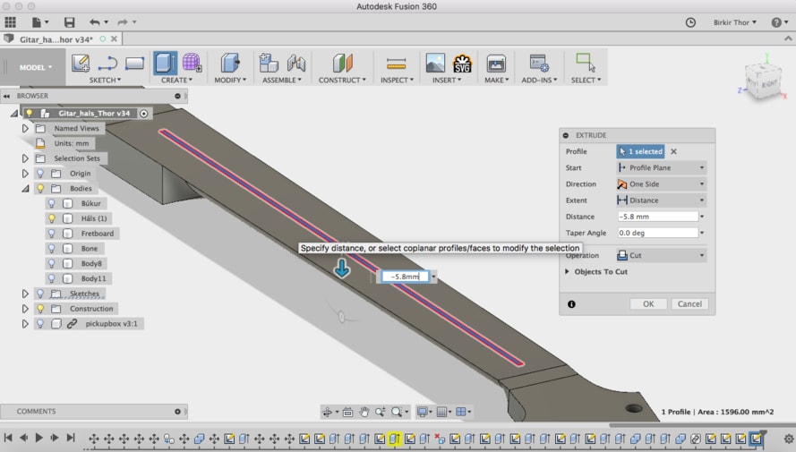
Then I made a thin hole for the trussrod. It should fit correctly on the sides but I had to add 2 mm on the top. I measured the trussrod and made a hole and extruded it.
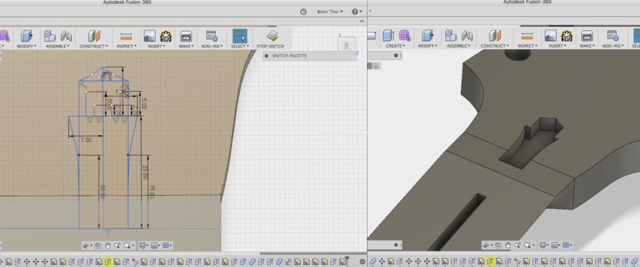
I designed a pocket for the truss rod adjustment.
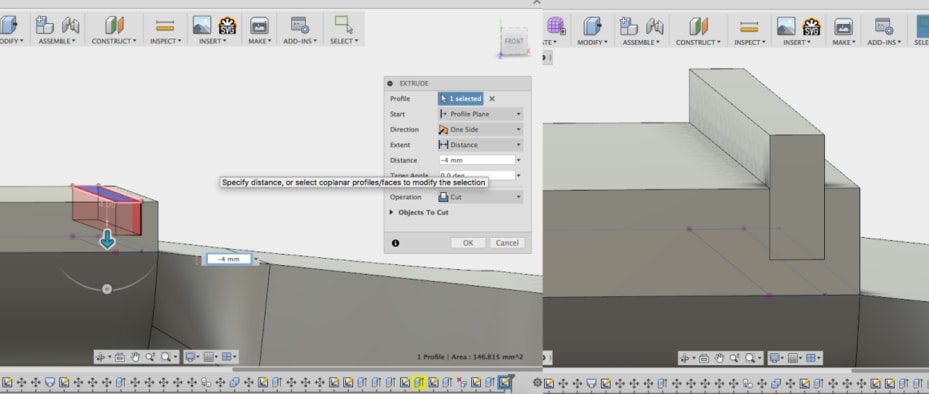
Those are the pockets for the LED lights in the plexiglass. Each LED is 5x5 mm so the pocket is 5 mm and the board itself is 15x15 mm, so the bigger pocket is 15 mm. The LED should fit perfectly. The image below is of the pockets for the bridge which I extruded threw the guitar body. Because the LED lights go through the holes and the cable also.
Those are the holes for the LED light on the pickup holes on the plexiglass. Also 5x5 mmm.
This is how the plexiglass looks like when it's ready. I made five holes for the screw which are 2 mm each.
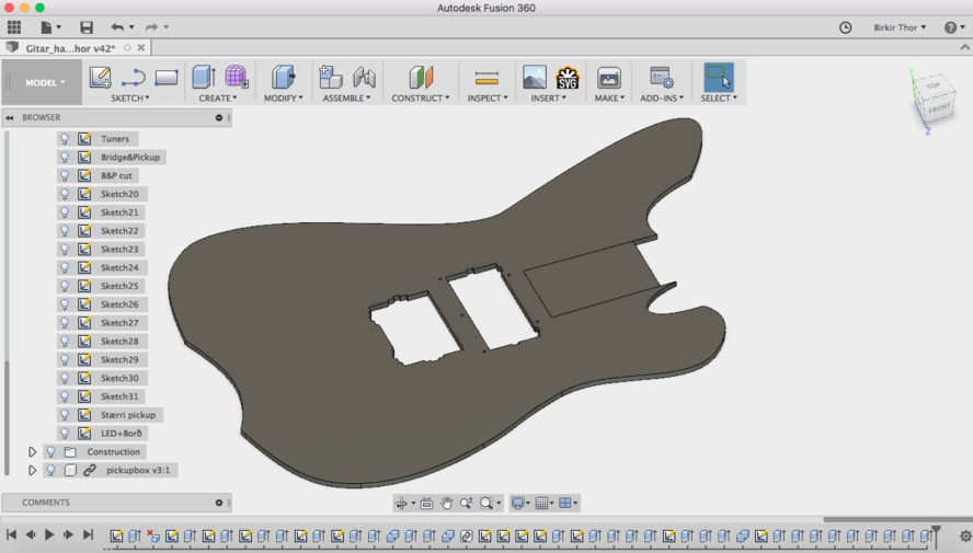
This is how the guitar should look like, without the bridge, pickups, strap buttons, tuning machines and the strings.
I made big space behind the guitar for all the electronic system. I didn't measure it I just assumed it would be enough.
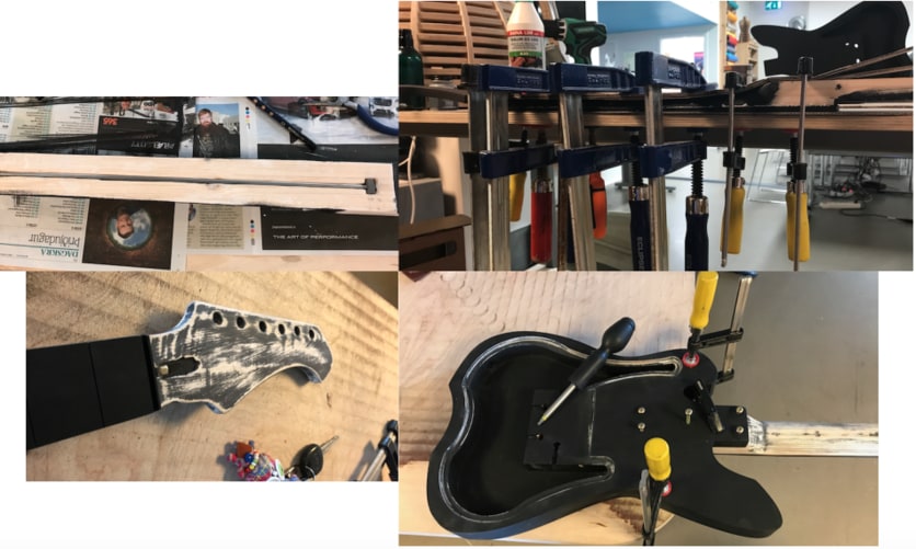
MAKING THE GUITAR
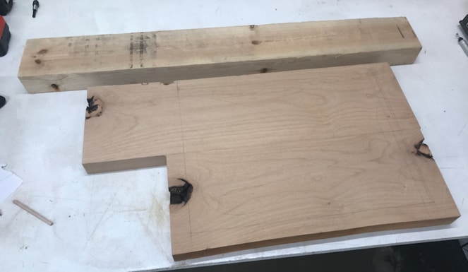
This is the wood I was going to use for the guitar, adler and pine. The adler is for the body and the pine for the neck. The pine is not a good wood for a neck because it will probable bend, but I have ebony fingerboard that will keep it from bending as much.
I saved the guitar as a STL file from Fusion360 and opened it in Inkscape and prepared it for VCarve Pro. I did the same for the fretboard which I was going to laser cut and then mill in the ShopBot.
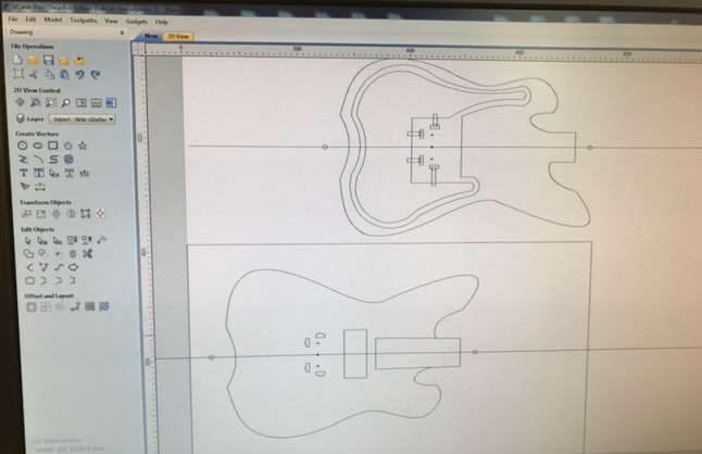
This is how it looks like in V-Carver Pro before the milling. I am using the pin method to move the guitar body when I need to mill the back.
All the lengths can be seen in the Fusion 360 file which can be downloaded on the bottom of this page in Download Files.
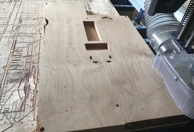
This is how the body looks like when we had finished the first tool path with 1/4 inches End Mill. I had to put a 2.7 mm End Mill for the bridge screw holes.
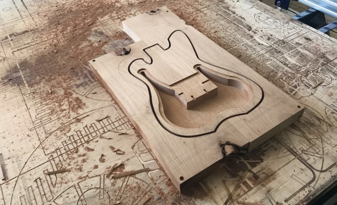
This is how the back side looks like. The guitar body is stuck to the wood with four taps which I hammered off to separate from the leftover.
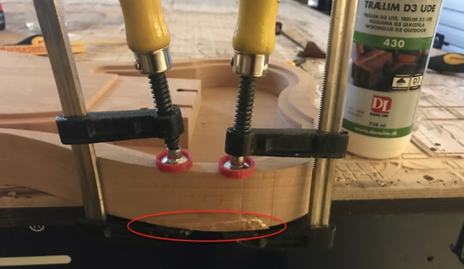
The milling speed was a bit fast so the milling bit ripped of some wood that I fixed by gluing.
Here is a closer view of the part that got badly damage. I managed to fix it with glue and by sanding it afterwards.
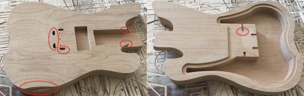
When I put the bridge on the guitar I saw that those three holes needed to be a little bigger, so I made them bigger. Also the screw holes were not perfect, but I managed to screw them and everything was okay.
Next was the neck. I took of it few centimetres to get the core of the wood. Then I put taps so it wouldn't move when milling. I prepared the sketch in V-Carve Pro. First was the roughing toolpath and then finishing toolpath.
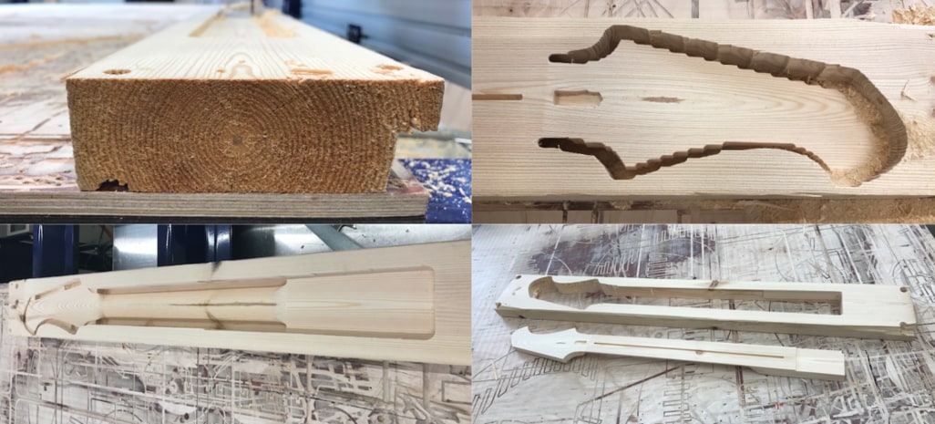
Everything went well except I forgot to make a hole for the thing that holds the truss rod in place. The neck was too tight to fit in the neck vase so I had to sand it until it would fit correctly.
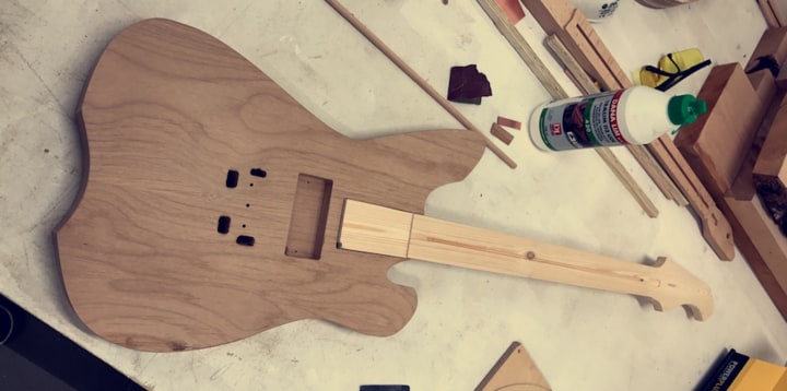
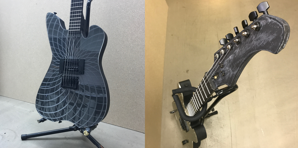
This is how the guitar look like unpainted and without any components.
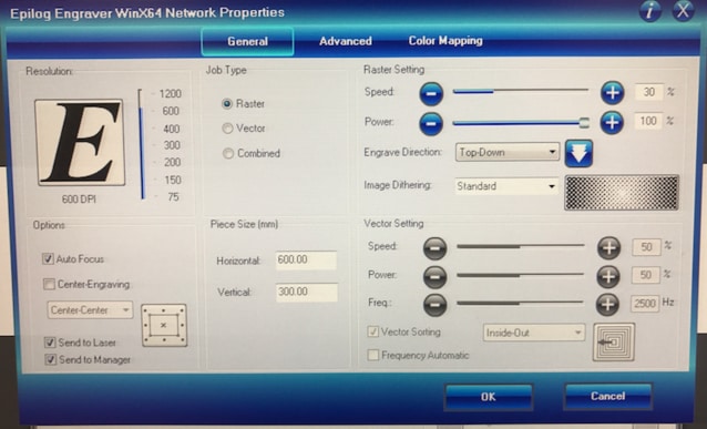
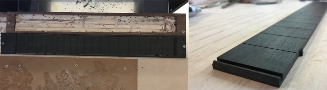
The next step was to make lasercut the freatboard. These are the settings for the raster on the ebony fingerboard, it was the first time doing it so it was basically a test.
This is a short video showing the Epilog laser cutting the frets on the fretboard. The video goes to slowmotion.
Laser_Fretboard from BirkirThor on Vimeo.
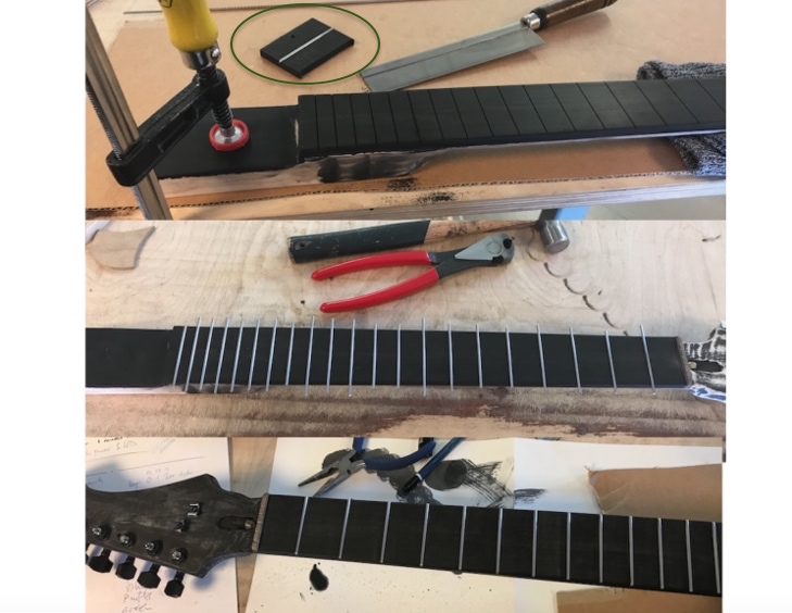
Here I am milling the freatboard with the Shopbot. The Laser cutter didn't cut deep enough so the Fab Lab manager bought a special saw for the frets. But we didn't get it right away so the guitar had to be fretless for sime time.
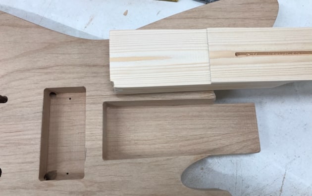
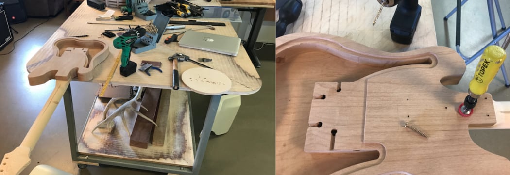
Here I am making a screw holes for the neck and body. I had to do it correctly so I used clamp to hold and support while drilling.
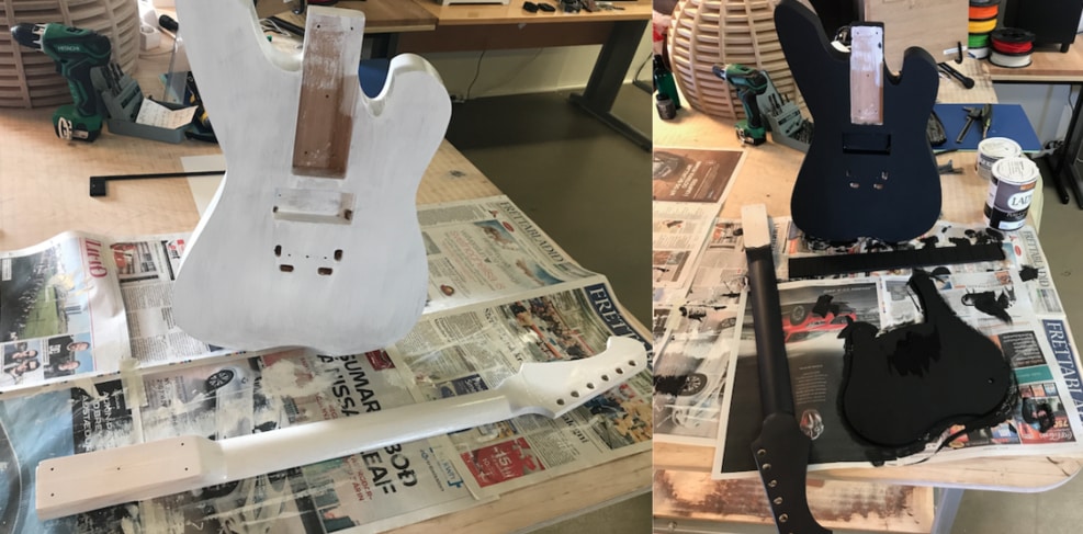
After I sanded the guitar I paint it with interior and then matt black and the fretboard with a special black ink for freatborads from Stewmac. I painted the neck dark purple just for fun. I made a laser cut Plexiglas cover which goes behind the guitar which I painted black also.
Then I put the trussrod in the neck on glued the fretboard on it. I put a lot of clamps to hold it for the night. Then I screw the neck to the guitar with five screws.
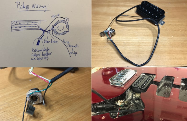
I was only going to use one pickup and an output jack so I made a sketch to see the set up. I solder the pickupwires to the output jack and made a test on a guitar that I own to see if the soldering worked. I got sound from the guitar so the wiring was correct.
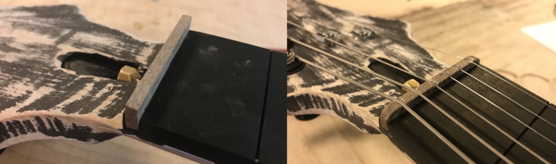
I made the nut out of antler. It was my first time making it. I made it by hand like you can see on the image. First I sand it with the machine and then by hands.
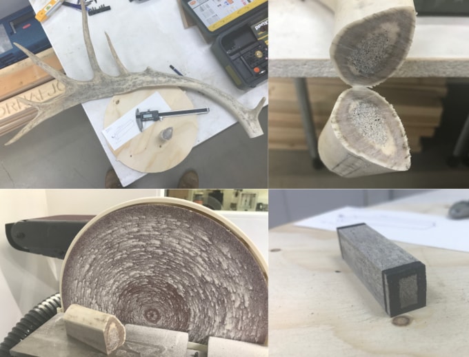
The nut fit perfectly. Then I used a little sand machine to make the cuts for the strings and I went to deep. I will make a new one later, but it is okay for now.
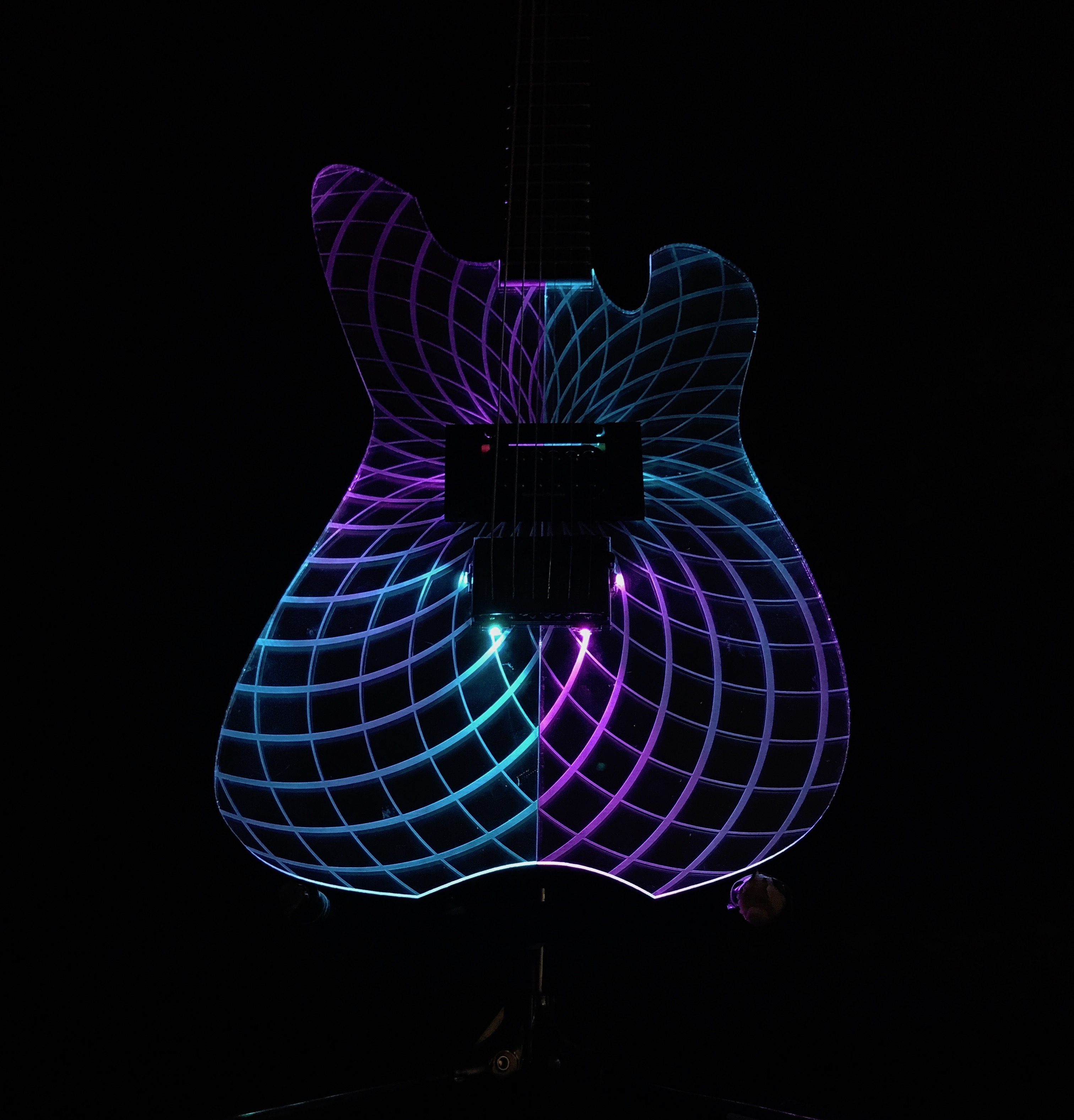
TEST WITH PLEXI AND RGB LED
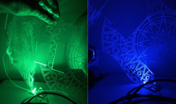
I made a little test with 5 mm plexiglas to see how the lines would light up from the LED lights. I took both of the photos from google. I wanted to see the outcome from straight lines like the mandala and an image like the lion. The guitar will be made from wood and the plexiglas will be on top with an engraved image on which will be lighten up.
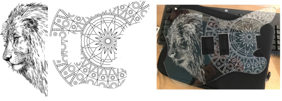
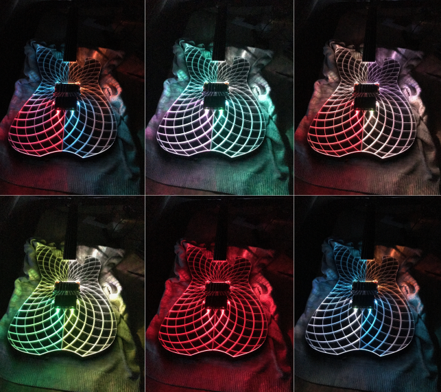
I decided to have lines instead because they performe better. I used one RGB LED for this test. The RGB LED lights are really bright so I knew after this test that I didn't need many to light up the plexi.
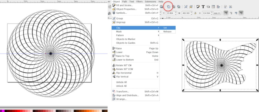
I imported the mandala I was going to laser cut on the plexiglass in Inkscape. I set one guideline on the middle of the guitar and put the mandala in the middle also. Then I selected the guitar body and clicked on the button which is in the red circle. Then I selected the guitar body and the mandala and went to Object --> Clip --> Set, then it looked like the image on the right.
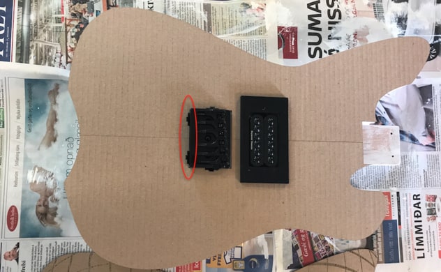
I lasercutted a cardboard test to see if all measurements were correct. I saw that I needed to make the holes for the LED lights a little bigger.
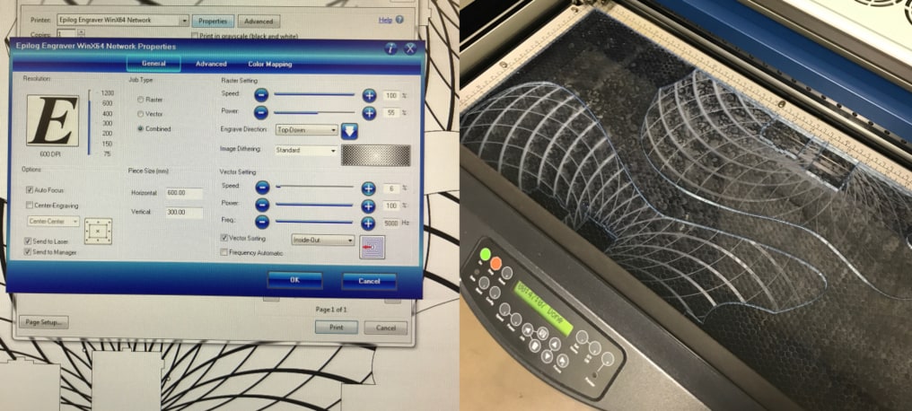
Then I laser cut the 5mm plexiglass. The settings are on the image to the left. It is combined because the mandala is raster and everything else vector, cut threw. The laser cutter in the Fab Lab is 300x600 mm so I had to split the plexiglass like you can see on the image on the right. It took 47 minutes to finish, and everything went well.
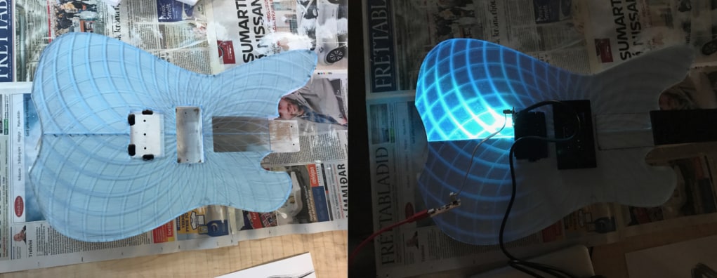
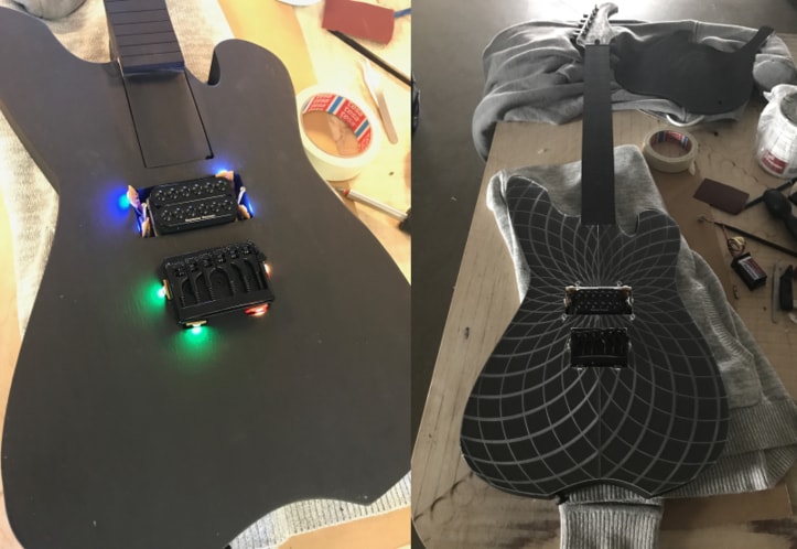
Then I put the plexiglass on the guitar to see if everything was okay, I needed to fix one thing, the srew on the right side on the bridge touched the plexi, so I had to sand a tiny part of the plexiglas and then everythng was okay. The guitar was white at this moment because I had paint it with white interior. I used a RGB LED board that I had made in Week 15 to test the illumination.
Here is a video clip of changing colors, running arduino code.
LED Test from BirkirThor on Vimeo.
MAKING THE BOARDS AND PROGRAMMING
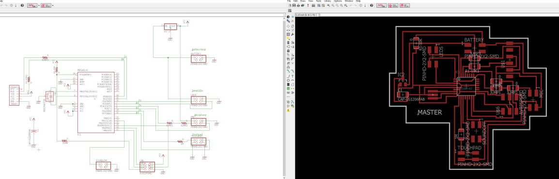
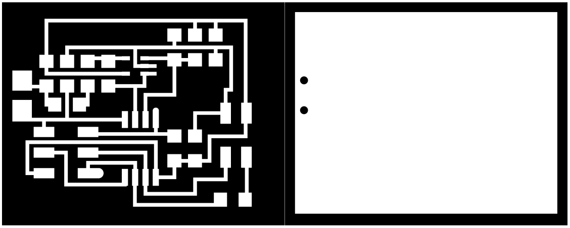
This week I designed-, milled-, soldered- and programmed the boards. I started by designing the boards in Eagle. I won't go into details in how to make a circuit boards, you can see more details in Week 6. I started designing the master board, I thought about what it should do and then wrote down the components I needed. Then I added the components in Eagle and made the schematic. I could have had the board smaller and the components close to each other. On the image to the right I had connect all the components, there is a one zero resistor footprint that I fixed in Photoshop. All the components for the master board are following:
- AtMega328
- Resenator 20MHZ
- FTDI cable
- 4 pin header x5
- 6 pin header
- Regulator 5V
- Capasator 1uf
- Resistor 0 ohm x5
- Resistor 10K ohm x2
- Resistor 1M ohm
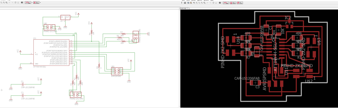
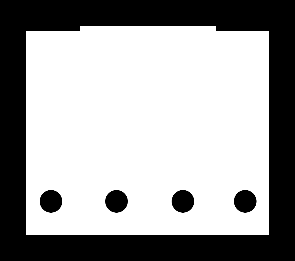
These are the schematic of the LED boards (slaves). It was the same process like the masterboard. Following components for the LED boards are:
- ATtiny44
- Resisor 4990 x6
- Resistor 10K
- Resistor 0 ohm x3
- 6 pin head
- 4 pin head x3
- Regulator 5V
- Capasator 1uf x2
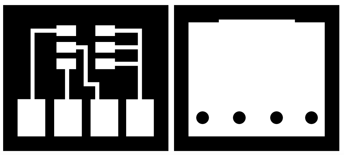
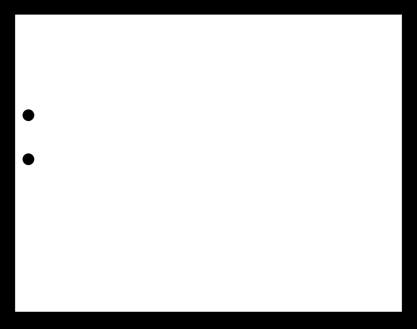
This is the RGB LED board. Only one LED goes on it with four wires connected to the LED (slave) boards. One slave is connected to two RGB LED lights. The board is so simple that I made it using Photoshop. The pins that are connected to the same lines are ground. The other pins are the colours. They are not connected in same order on the slave boards. I made eight boards like these, except one board was different, because a screw attached to the bridge that was in the way. You can download both of the boards in Download Files on the bottom of this page or download it from Final Project.
This is the sound sensor board. It is the same board that Neil have in Input Devices except I changed it a little. Instead of using the FTDI cable I put 4 pin header instead, GND, VCC, TX and RX. I added a 10K resistor between TX and the PB1 pin on the ATtiny45. I changed it in Photoshop, because I only exchanged the FTDI to 4 pin header and adding one resistor and holes where the mic is. You can see Neils board here.
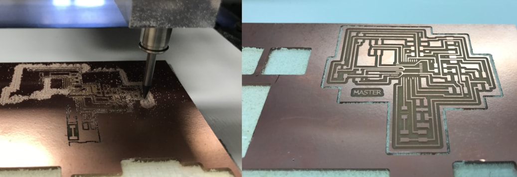
Here is the Roland MDX-20 milling the masterboard.
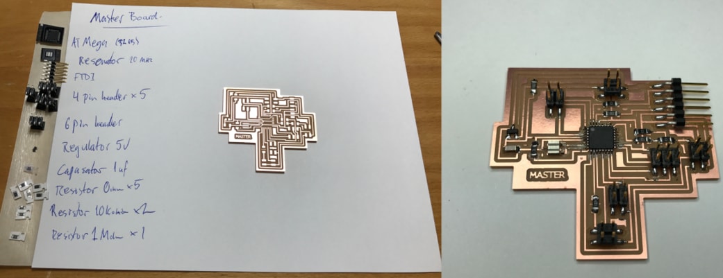
I always write down the components and put them on a tape beside it. It was my first time soldering ATMega so it was difficult because the pins are so small. Everything else went well and you can see the board before and after soldering. The components are on the list on the image below and are also listed above.
Those are the four LED boards (slaves) and the Mic (sound sensor) board. The components for the LED boards are on the list on the image below and are also listed above. Here is the list for the mic board:
- MIC COND ANALOG OMN I -38DB
- ATtiny45
- 6 pin header
- 4 pin header
- Capasator 1uf x3
- Resistor 10K x5
- Resistor 0 ohm
- Resistor 1K
- IC OPAMP GP 24MHZ RRO TSOT23-5
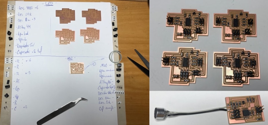
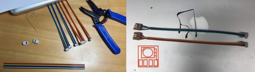
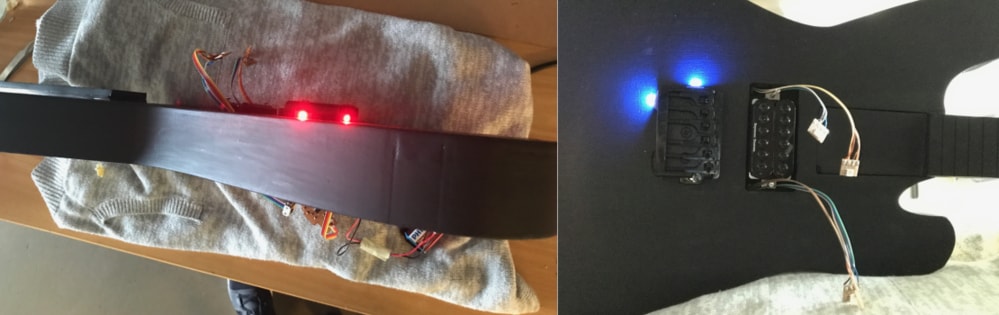
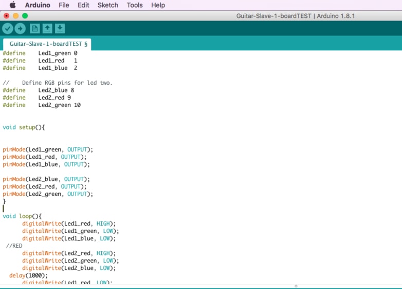
Then I made the cable for the LEDs. I made them long because they go a long way in the guitar. Then I soldered the LED on the small board. See on the red image how the LED should turn.
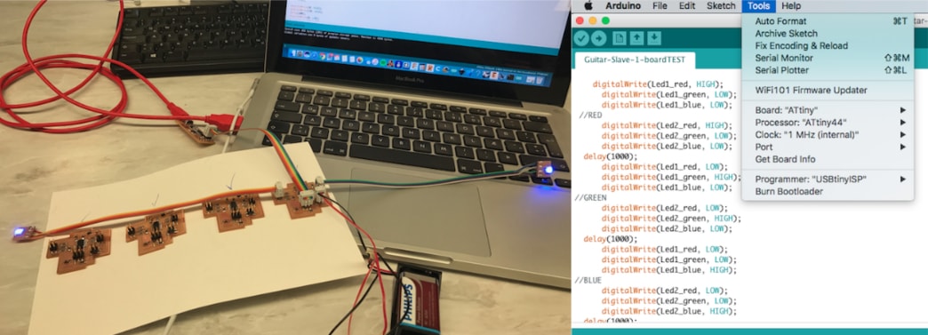
Then I tested the boards with a simple changing colors arduino code. You can download it in Download Files. All of the boards worked fine.
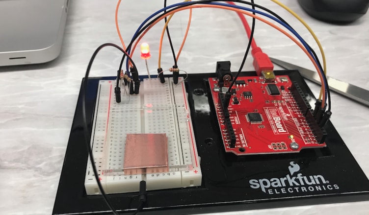
Here I'm making a touchpad test with Sparkfun Kit and Arduino code. When I touch the touchpad copper the LED turns on, when I touch again it goes off. I had also made a touchpad test in week 10, input devices, which I will use in my final project.
Here I am grounding the bridge. I sanded a piece of the bridge to get clear connection form the ground wire to the bridge. I had already ground the guitar with another wire (purple) so this was the second time I did that, because I was having some ground trouble, that's why I put this bigger wire instead.
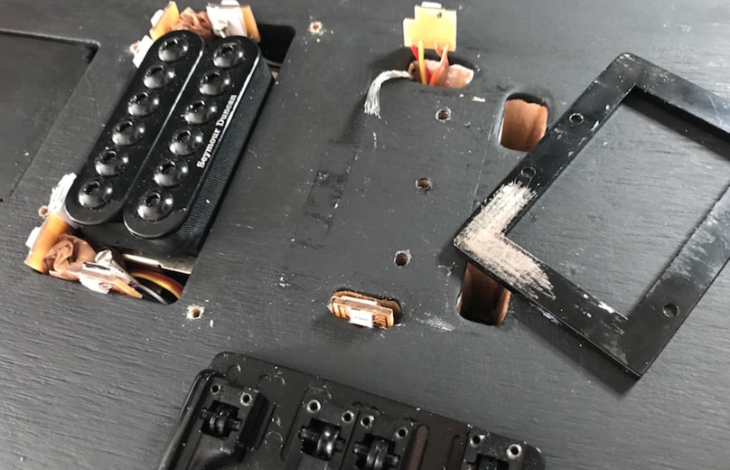
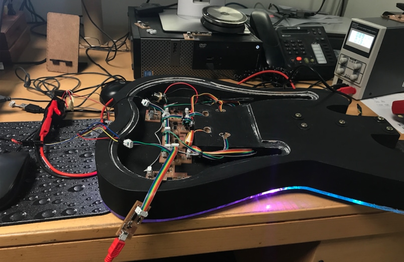
Here I'm installing the small LED boards into the guitar and testing it.
This is how it looks like when there is no plexi. I install the LED boards into the guitar and connect them to the slave boards later.
Here I am programming the boards to communicate. When I send from the master for example capital letter, the board with the following id should respond with a small letter. For example:
Master sends the id B, the board with the id B responds and sends to the master a small b.
This is called networking and communications, you can see a video example in week 15.
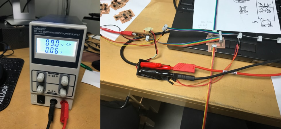
The masterboard is connect to the four slave boards with a 4 pin headers with a cable. The FabISP programmer is not giving the boards any power, they are getting 9V power from the power supply threw the battery compartment. I also had to take the red wire out of the FTDI cable because the board had a 5V regulator on it, or else it would overload it the regulator and overheat.
I was having some commutication trouble with the boards. We tried many things and made some tests to see what worked and what wouldn't work. We were waiting to get an oscilloscope. More about that below.
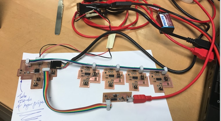
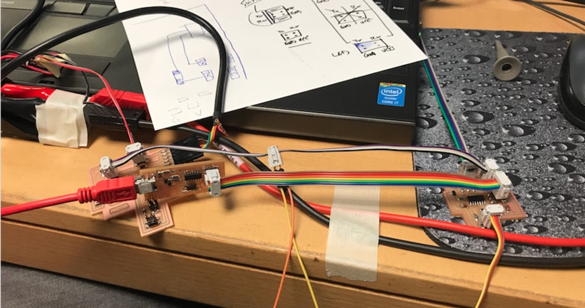
On the image to the left is the power supply, red goes to red and black to black. Here I am cheking if the LED board is okay, which it turned out to be.
SERIAL COMMUNICATIONS TROUBLE - USING OSCILLOSCOPE
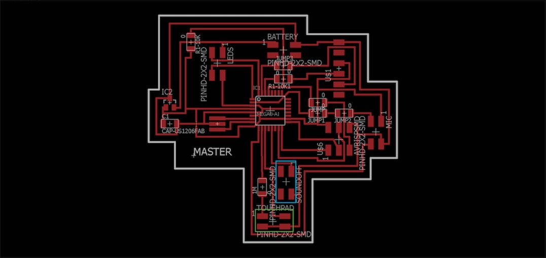
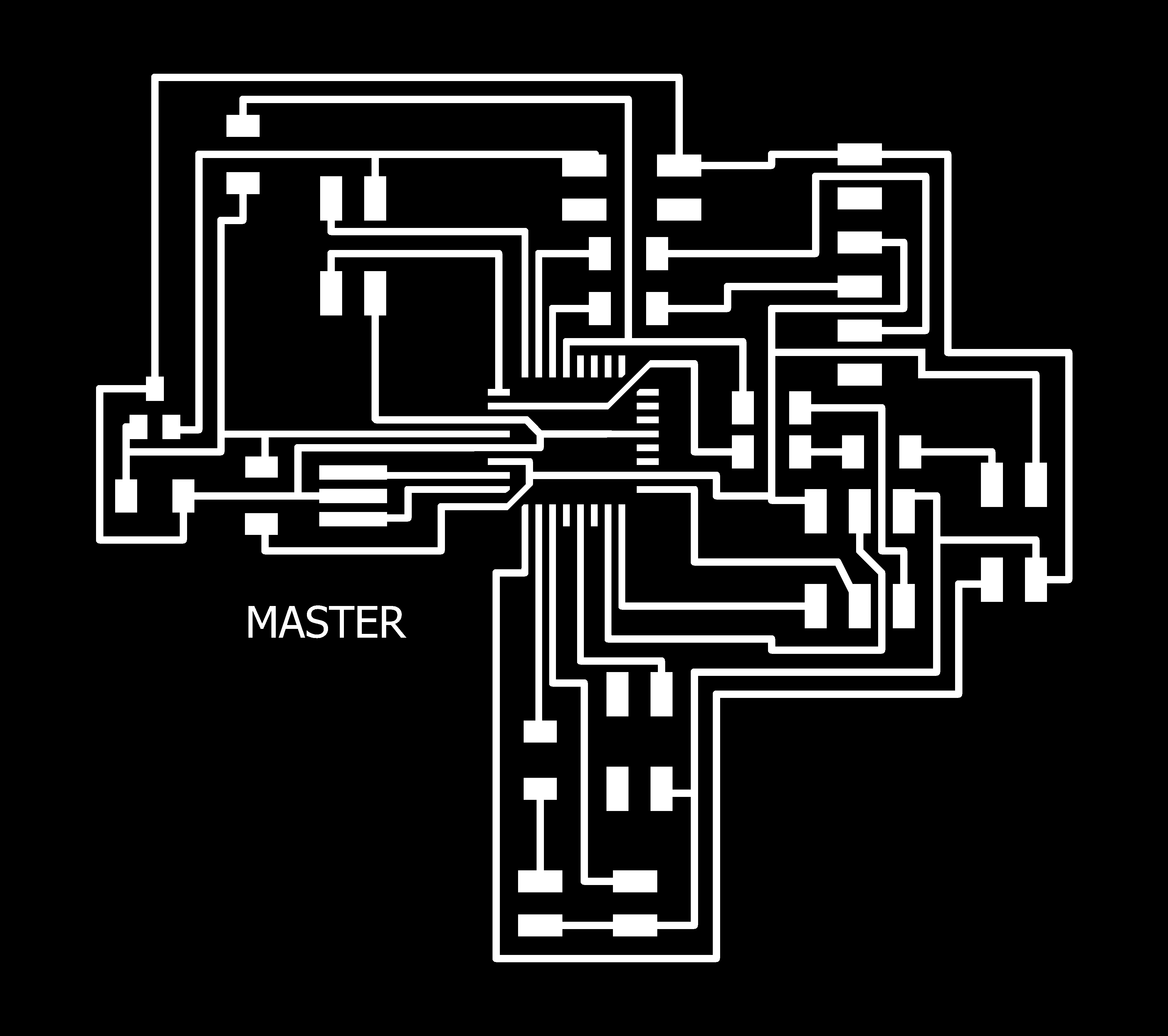
This is the schematic of my master board that I will use in my final project. There are more information about this board in Week 19, Project Development. I did not make this board in this week but I put the documentation here because it has to do with networking and communications.
I was having some serial communication trouble between my master board and LED boards (slaves). Me and my Fab Academy instructors had been trying to find out what the problems were for some time and in many different ways. We had to get an oscilloscope to see if we are getting the right signals.
Arduino codes for this project can be downloaded below or in Download Files.
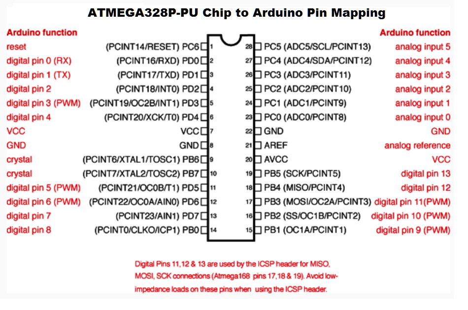
It is necessary to have the right pin configuration when programming in Arduino or else it wont work. The image below is a pin configuration for the ATMEGA328 microcontroller.
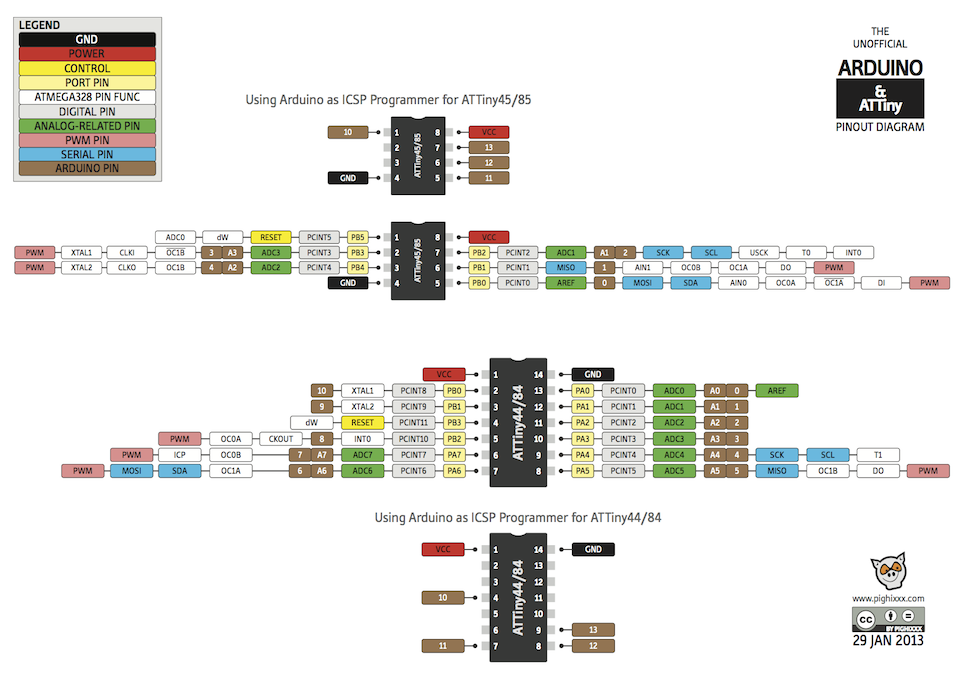
Here is an image of the pin configuration for the ATtiny44 and ATtiny 45 that I used when I was programming the LED boards and the sound sensor board.
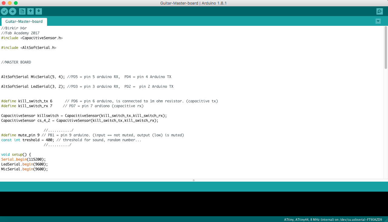
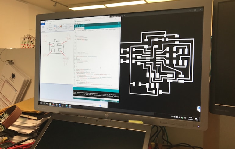
This is a part of the master board code in Arduino. I inclueded CapacitiveSensor.h and AltSoftserial.h that I use and define the pin configuration by looking at the schematic I had made and the pin figuration image above.
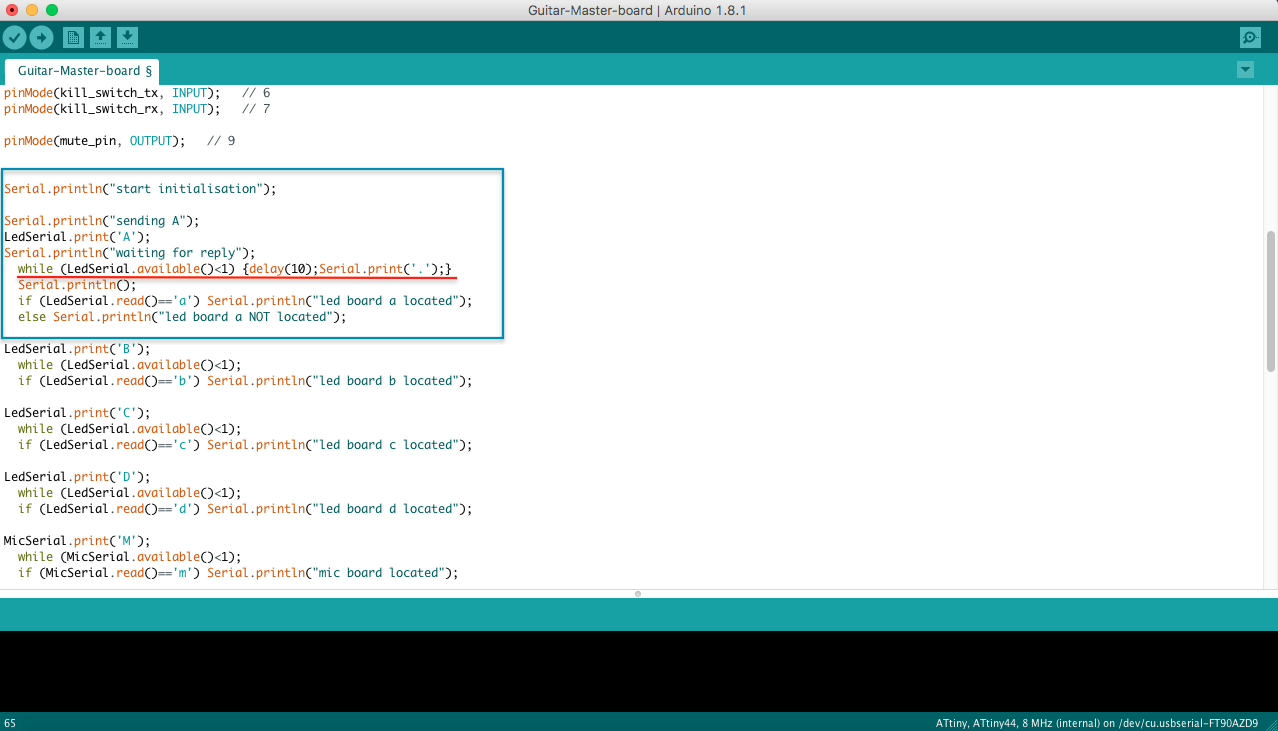
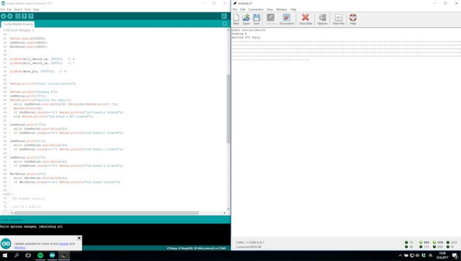
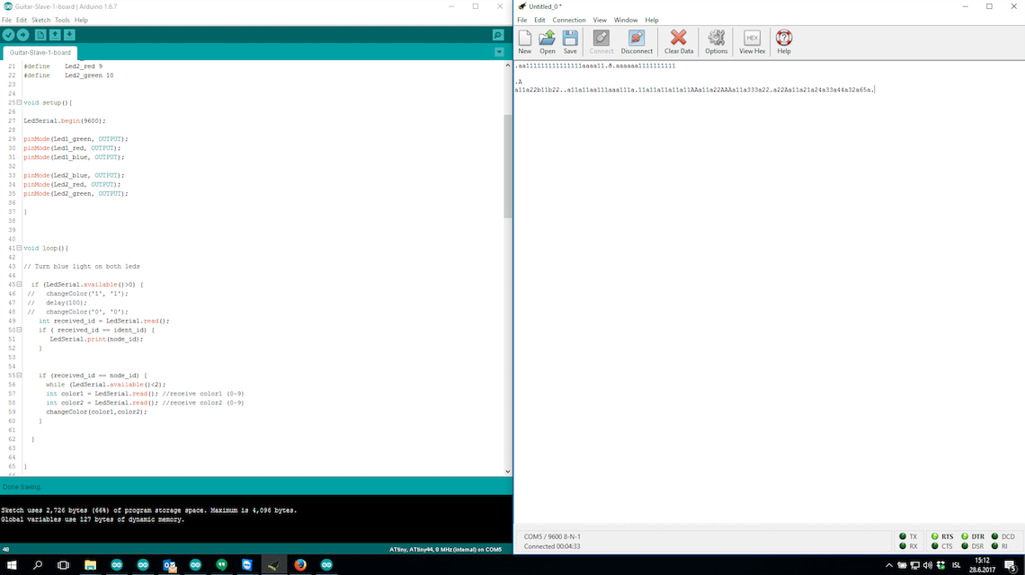
This is the same code as above. Here I'm communicating the other boards with serial. I've been having some troubles with serial communications which I didn't find out during the Fab Academy 2017. But in the blue box is the test I had been using to find out if I was Receiving anything or not. Unfortunately I didn't receive anything from the LED boards, more information about that below.
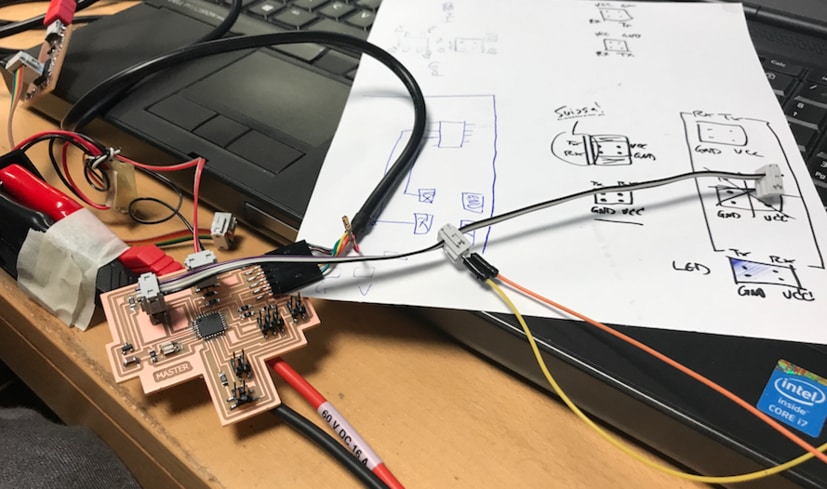
I am using a power supply to power everyting so I don't have to finish my battery on this. The VCC (red wire) has been removed on the FTDI cable so it wont overheat the 5v regulator. This is how the setup is for this experiment on the master board. I am using another FTDI cable which I connect two wires in, TX and RX to see if I am getting any signal from them. I got a normal signal from this, see on the image below.
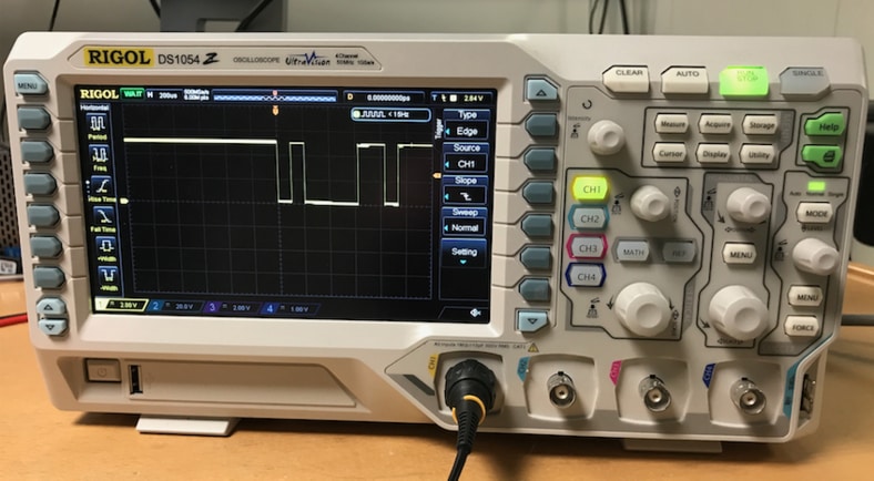
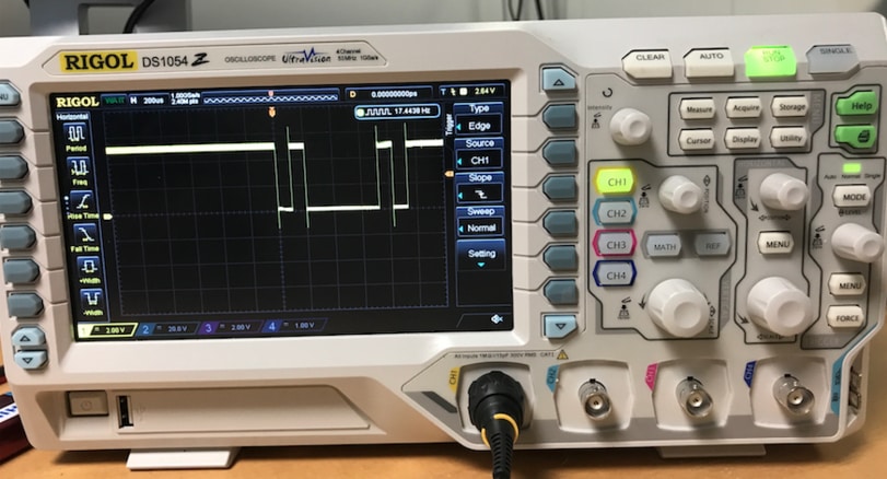
This is a photo of the oscilloscope of the signal when I send big A from serial monitor.
Here I am doing the same with one of the LED boards. On the image I am programming it.
This image shows a normal signal when sending from serial monitor to RX.
When we connect the master board and the LED boards together the TX (transmitter) sends but doesn't get answer back. Like when I send big A from serial monitor and should get little a, it doesn't happen. That's were the problem is. We have been using multimeter and oscilloscope and trying everything we know.
On the image we are going threw the pin figuration and if TX and RX are correct, which it was.
Here I am waiting for reply from the slave A (LED board) but I'm not getting any.
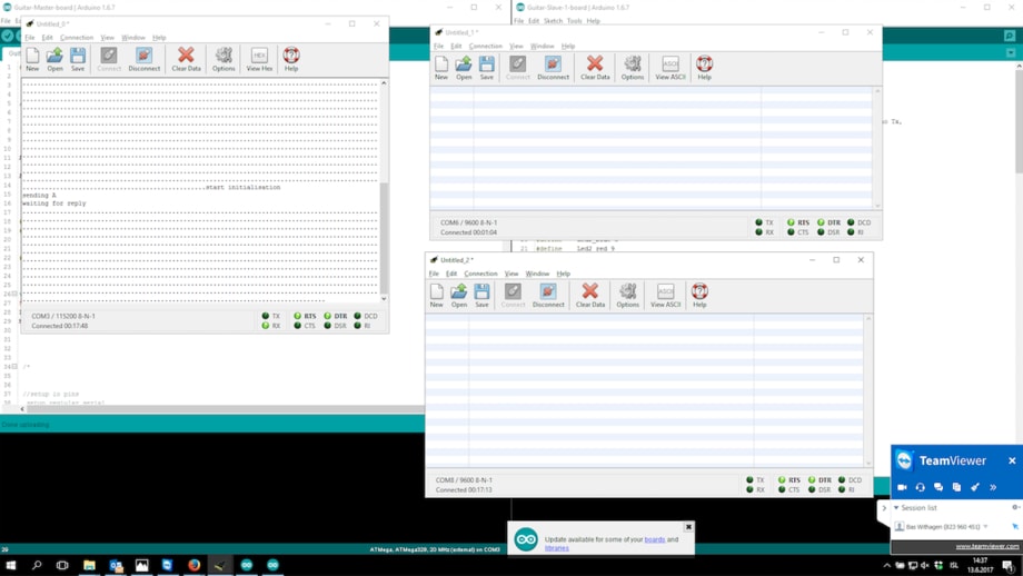
There I'm using three FTDI cables to check if I was getting any signal. One FTDI cable was connect to the master board and one to TX and the other to RX. On the serial monitor to the master is waiting for reply but the other to the right aren't showing anything. One window is serial monitor in Arduino and the two other are CoolTerm.
I got a respond from the LED board (slave). I was using three FTDI cables and sending node id from a serial monitor from the computer, I was not using the master in this test. When I send capital letter the board with the same letter responds with the same letter, just the small one.
LED Serial from BirkirThor on Vimeo.
TOUCHPAD TEST FOR MY FINAL PROJECT
In this video I am showing the values coming from the touchpad when I touch it. I am using the master board which is connected to the FTDI cable and powered with a 9V battery. I took the red wire (VCC) of the FTDI cable or else I would burn the 5V regulator. This is a test that I would develop and have in my final project. The idea is when I touch the copper plate the value goes up and when it goes over certain threshold it turns on a pin on the ATMega which gives power to the guitar through two wires (4 pin header) and therefore changes the plus to minus and mutes the sound.
On the video below the values change when I touch the copper plate.
Touchpad_Test from BirkirThor on Vimeo.
This is the master board. In the green box is the 4 pin connector that is connect to the copper plate (touchpad). One pin is TX (the one with the 1 M ohm reistor between) and the other one is RX, the two others are ground.
In the blue box (I call it sound off) is the 4 pin connector that connects to the pickup and the output jack on the guitar. On pin is ground and the other one is connected to one pin (PB1) on the ATMega.
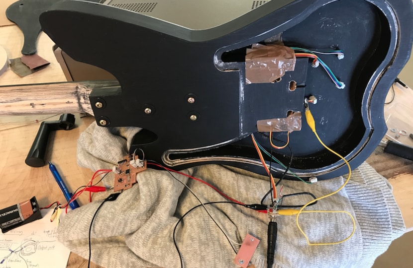
This is how the connections looked like when I was testing it. The sound off/4 pin connector is connected to the PB1 pin on the ATMega, it goes to the black wire on the output jack (-) and the ground pin goes to the ground on the guitar (+) which is on the output jack.
I was having some troubles grounding the guitar so I put an extra ground to the guitar body itself which is the yellow wire. It's done by putting a screw on the body and wire from the ground on the output jack on the screw. Unfortunately it didn't fix the problem.
In this video I am testing the touchpad/copper plate. I have every thing connected and when I play the guitar and touch the copper plate the sound goes off. There is a high frequency clicking sound when I touch the copper plate, but it works. Also it takes the sound few seconds to com back on after I have muted it. I have to develop this and debug to have this work as I want.
The Arduino code can be downloaded below or in Download Files.
Touchpad_mute pin from BirkirThor on Vimeo.
FINISHING THE GUITAR
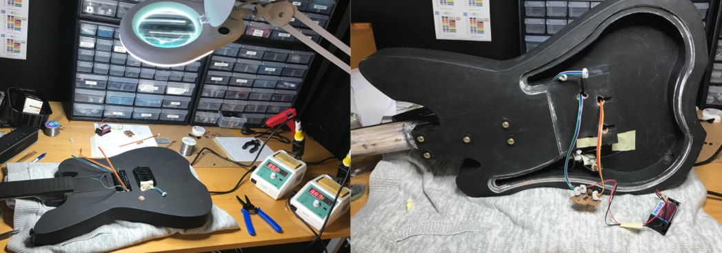
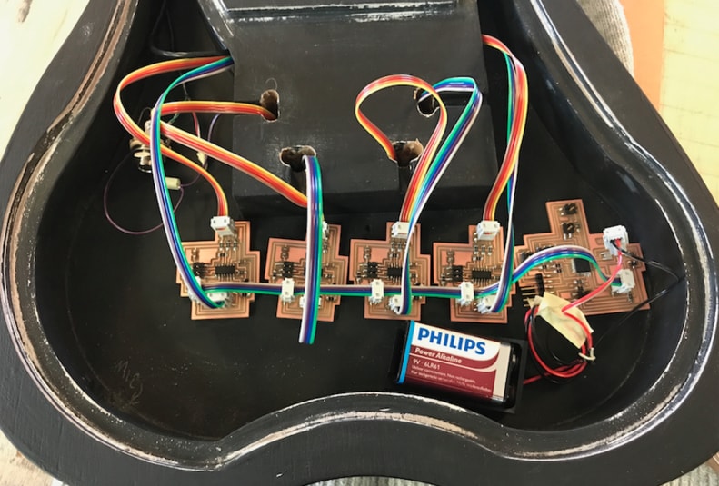
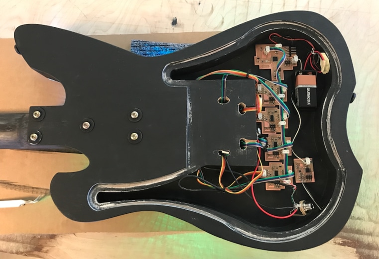
That's how the boards are inside the guitar. Master board and four LED boards connected to eight LEDs. The organized the cables after I took this photo. The cables that are connect to the LEDs are the same length, but when I do the next guitar I will have them as they can be.
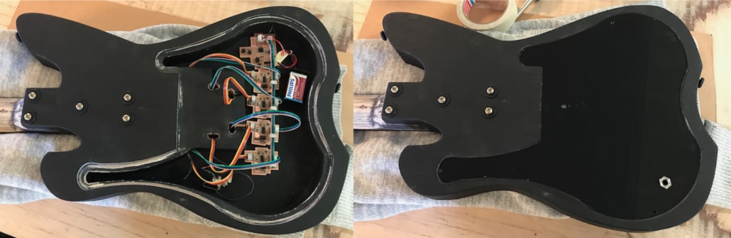
This is the back of the guitar. Five screws in the neck, lasercutted plexiglass that I painted black, the guitar output comming out of the plexi and the circuit boards. The boards that are not on the image is the sound sensor (mic) board and the touchpad.
Because of the communication trouble and a lack of time I made simple arduino code of changing colors, so the code was running the same 17 seconds loop over and over again. You can download the code in download files.
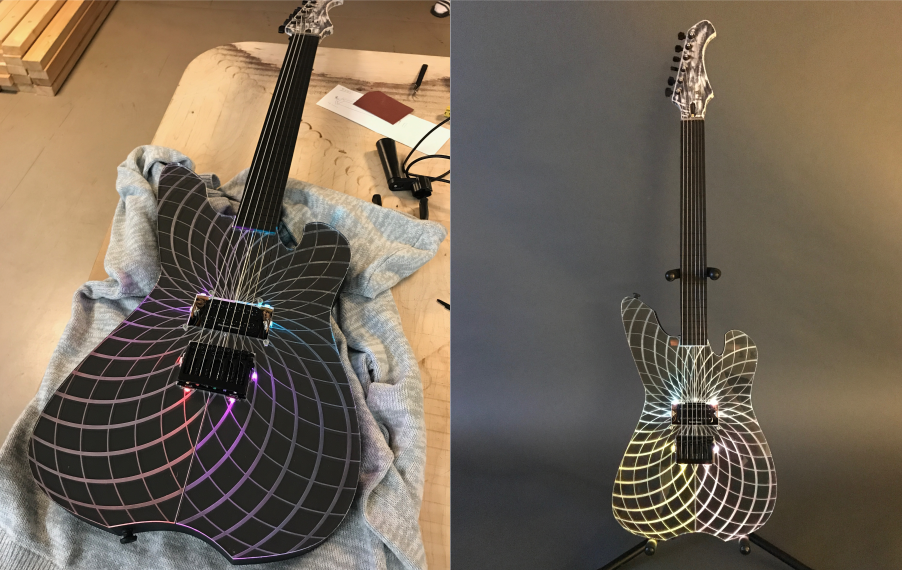
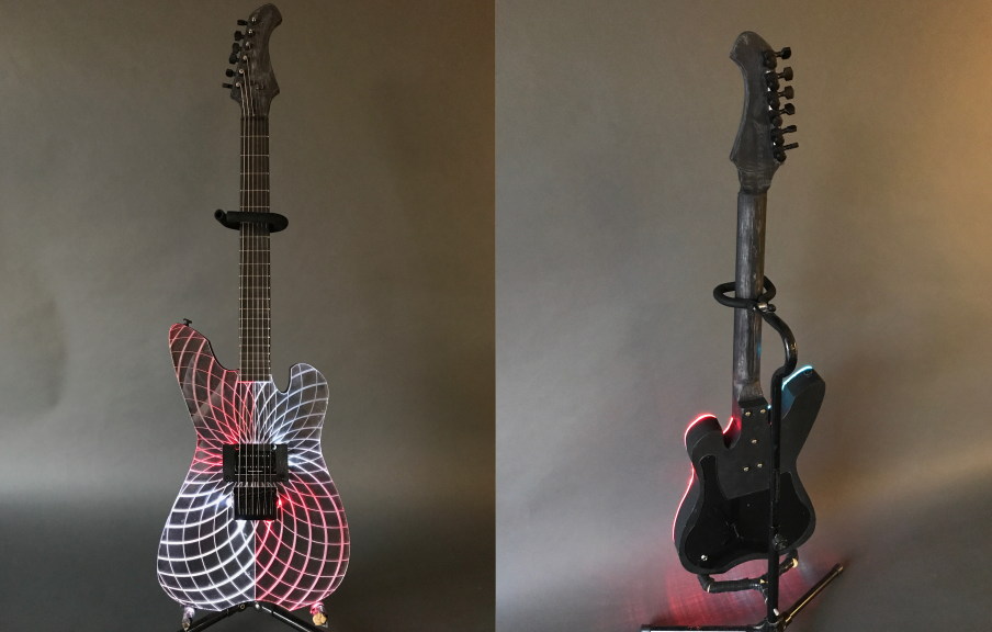
This is how the guitar looks like without the plexiglass and with it. I had to make a bigger screw holes in the plexiglass by drilling by hands because I didn't find 2 mm screws. The holes where 2 mm and now 3 mm. I had to be careful when screwing the screw in, so I wouldn't brake the plexiglass. Then the only thing I needed to to was to make and put the nut in place and then the strings.
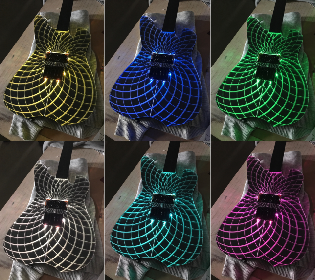
This is how the guitar looked like for the presentation. Not finished yet. The boards are running on 9V battery. The code I wrote runs the same color on same time, but for some reason there are some difficulties with the time. So the LED lights start on the same time, then after few minutes everything is random. But the engraved patterns on the plexi performs really well.
FINAL STEP
On the last Fab Academy week I put frets on the guitar. I did a test before I put in the guitar itself (see in the green circle). I had laser cut the frets before but it didn't go deep enough. I saw the frets with a special saw and then put the frets in right places and hammered them in. I also painted the neck black.
This is how the guitar looks like on the inside. It has pickup, output jack, master board, four slaves, eight LED boards (the small ones which goes through the holes) and sound sensor board. The touchpad is not connected with the system on this image, if it would be connected it would go from the master to the pickup and the copper plate also to the master.
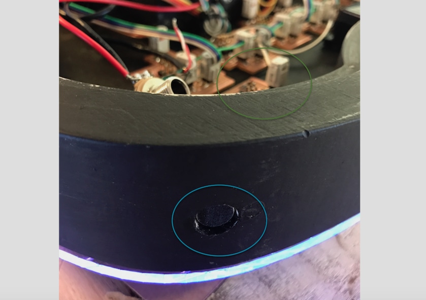
This is the microphone sticking out of the guitar (in the blue circle) and the sound sensor board in the green circle.
FINAL TEST
We found out that there is something wrong with the rx pin on the LED board. We can send information and change color but no respond from the boards. We also found out that one of the LED boards had a short circuit. In the CoolTerm window on the right I am writing colors so the LEDs change colors. Video below.
This is how everyting is connected. I am using power supply to power the boards and sending from the terminal threw the FTDI cable to the LED boards.
This is how it works.
LED CoolTerm from BirkirThor on Vimeo.
Here is a video showing when I write the LEDs id in the CoolTerm window and get respond from the LED board.
Respond_Fab Lab from BirkirThor on Vimeo.
PHOTOS
Then I put the strings on the guitar and the pick up riser. The guitar was finally ready.
CONCLUSION
Making this guitar with integrated electronic system as my final project has been very educational for me, which I have enjoyed doing. Not everything worked like I hoped for. I had some serial communication trouble with my final boards, we did not find a solution in time but I managed to make the boards work correctly individually. The LED boards worked as you can see on the photos of the guitar and performs well with the engraved plexiglass. The sound sensor board should have change the colors of the LEDs when low frequency is received, but because of the serial trouble it couldn't be done. See how sound sensor board works in Week 13.
The experiment of the touchpad worked, which was amazing, because at first I wasn't sure if it was going to work. When I touch a copper plate I mute the sound of the guitar, see in Week 13. The goal was to turn off the sound and the LEDs at the same time, but because of the serial trouble I didn't get at that point.
The question that still needs to be resolved is what is causing the serial communication trouble. I have made many tests and still not seing what it is.
Making this final project I have learned a lot about guitar building and electronics. I have combined all my knowledge from every weeks assignment to make my final project, step by step. I will continue to find a solution on the serial communicaiton trouble after the Fab Academy. I will continue this project and develop it and get more knowledge in electronics to expand my horizon and to be able to make things by myself.

This work is licensed under a Creative Commons Attribution-NonCommercial-ShareAlike 4.0 International License.
RELATED LINKS
DOWNLOAD FILES
Fretboard_Test - Right click to download
Fretboard.stl - Right click to download
Guitarbody.stl - Right click to download
Guitar.svg - Right click to download
Guitarbody.svg Mill - Right click to download
Guitarbody.pdf Mill - Right click to download
Guitarneck with holes .stl - Right click to download
Guitarneck with no holes .stl - Right click to download
Plexi Laser 600x300 .svg - Right click to download
Plexi Laser 600x300 .pdf - Right click to download
Plexi Back .stl - Right click to download
Plexi Back .svg - Right click to download
Plexi Inkscape .svg - Right click to download
Plexi.stl - Right click to download
Mandala .pdf - Right click to download
Misty Logo .svg - Right click to download
Guitar Body VCarve Pro - Right click to download
FINAL PROJECT BOARDS:
Master brd- Right click to downloadMaster Schematic - Right click to download
LED Slaves brd- Right click to download
LED Slaves Schematic - Right click to download
Master Interior - Right click to download
Master Traces - Right click to download
Mic Sound Sensor Interior - Right click to download
Mic Sound Sensor Interior - Right click to download
LED Slaves Traces - Right click to download
LED Slaves Interior - Right click to download
LED Board I Small Traces - Right click to download
LED Board I Small Interios - Right click to download
LED Board II Small Traces - Right click to download
LED Board II Small Interior - Right click to download
FINAL PROJECT ARDUINO CODES:
Master Arduino Code - Right click to download
Mic/Sound Sensor Arduino Code - Right click to download
LED/Slave Arduino Code - Right click to download
LED Lights(No Serial) Arduino Code - Right click to download
LED Lights Test (Terminal Window) Arduino Code - Right click to download
HAVE QUESTIONS?
Contact me!
Höfn, Iceland
Email: birkirthorhauksson@gmail.com
Swing by for a cup of , or send me a message :)