WEEK 13 - INPUT DEVICES
ASSIGNMENT
- Messure something: add a sensor to a microcontroller board that you have designed and read it
DESIGN THE BOARD
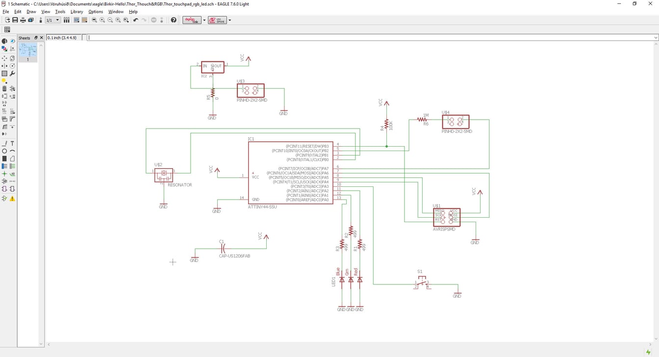
This week I decided to make a copper plate touchpad which I would use in my final project. The touchpad should sense when a person contacts the copper, that will give different resistant that Attiny 44 could calculate. That different types of values coming in when touching and not touching would be used to turn on and off the RGB Led. I have two boards, one RGB LED board and touchpad board which are connected with two wires. The Led board is similar as the LED board I made in week 10 (Output devices), the difference is I added another 4 pin header and 1 Mega ohm to connect to the touchpad. For more details on how to make your own circuit board go to week 6.
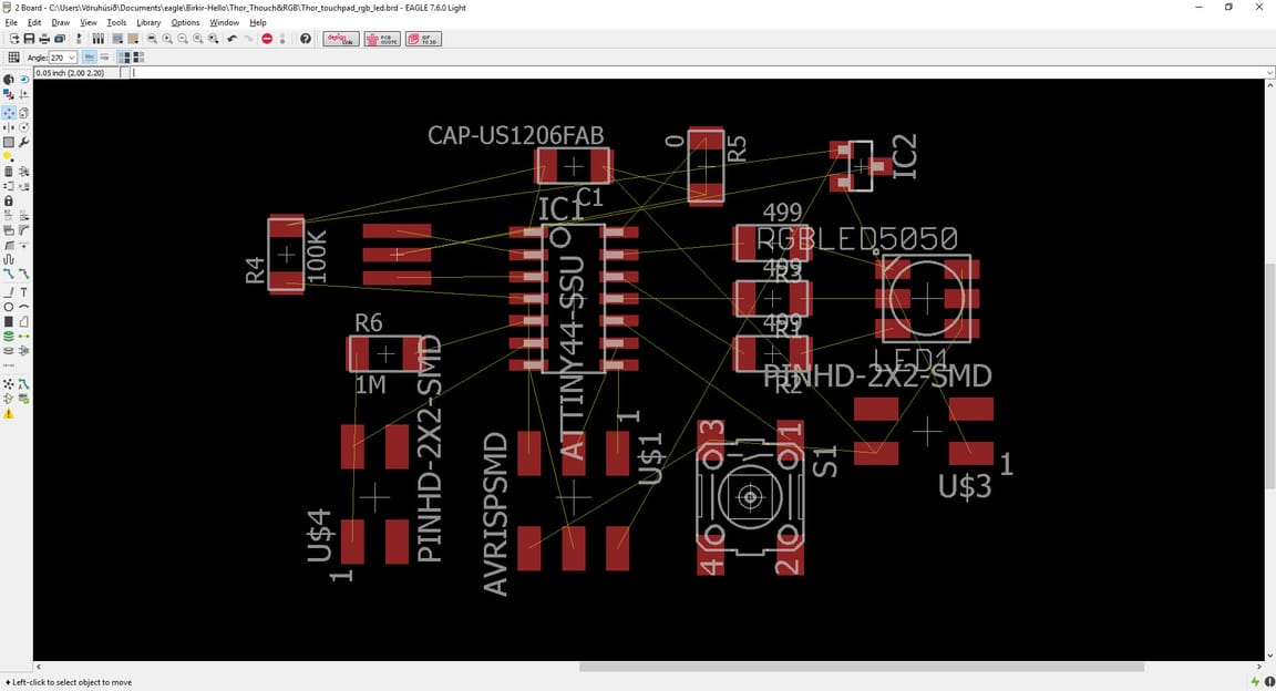
This is how it looks like before I connect the components in the right places. The yellow lines show the connections.
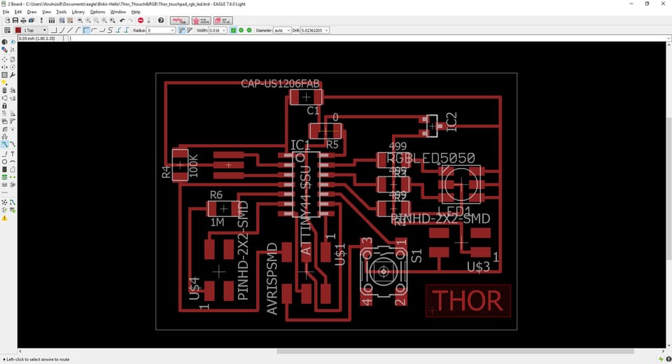
This is how it looks like when they are connected. It takes a little time to figure it out.
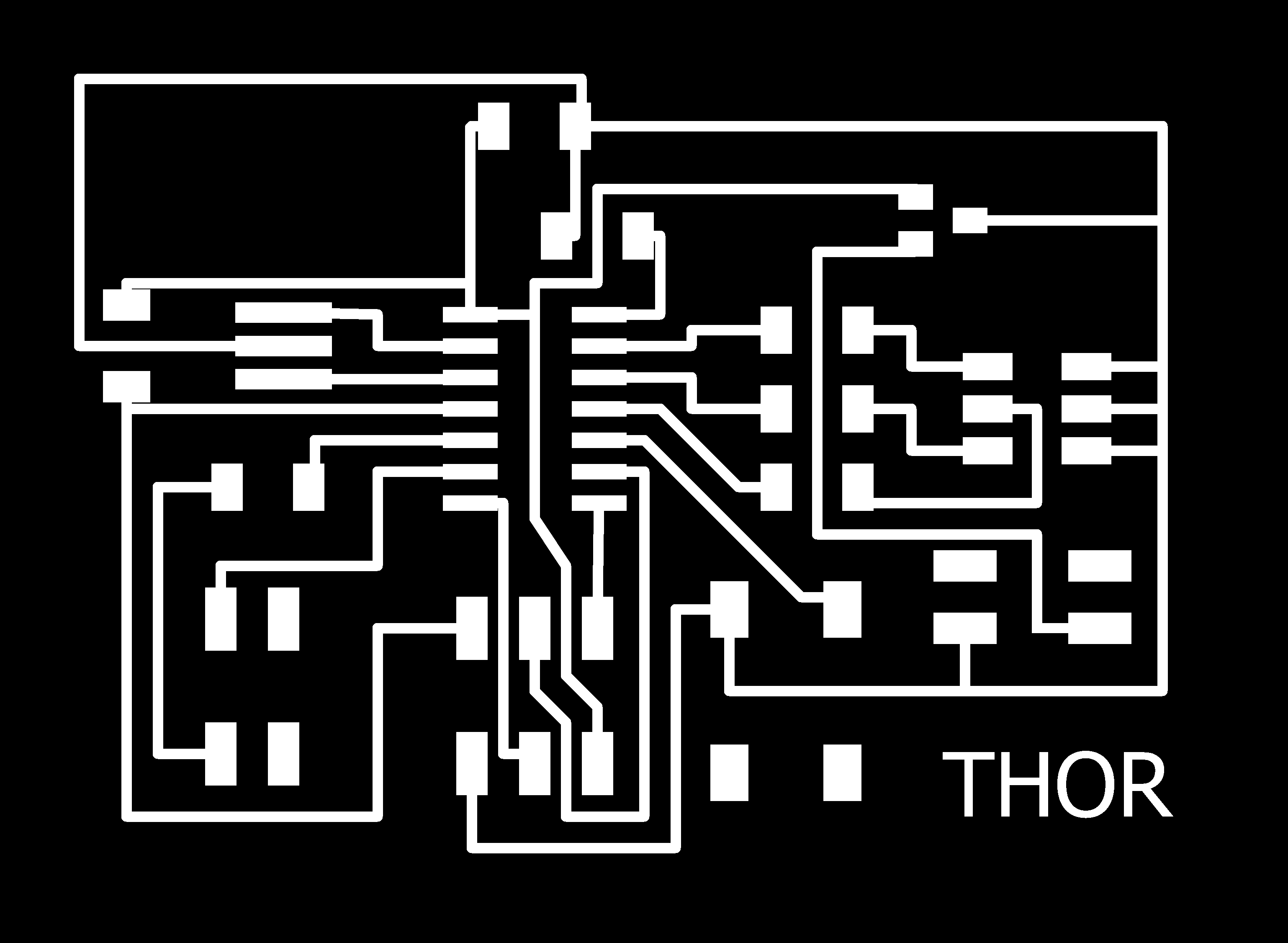
Then I exported it and used these PNG files to put in the fabmodules.org.
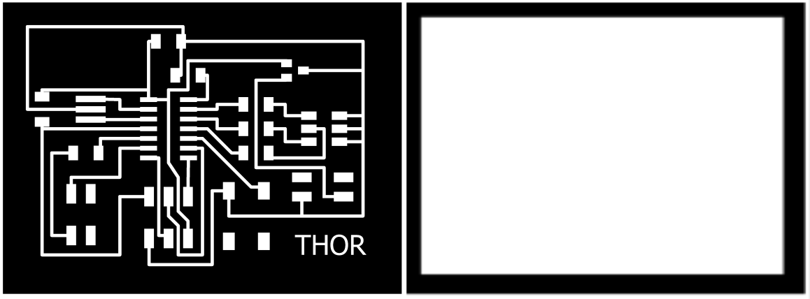
First I cut the interior with the 1/64 mill bit, then the cut file with the 1/32 mill bit. I could have saved more space on the plate by being near the one who had already be cut.
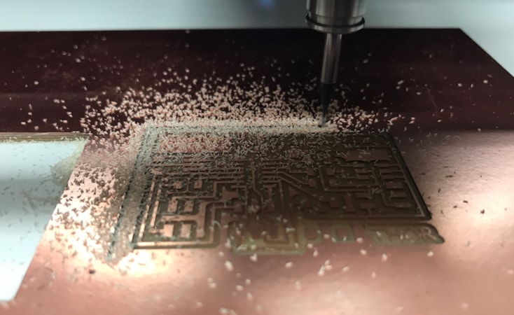
Then I drew the touchpad in Photoshop because it was really simple. I saved it as PNG file.

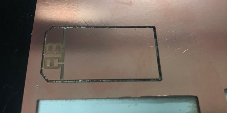
Then I cut it out and it went well.
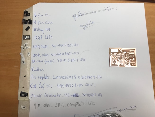
Those are all the components I needed for this board except one button I forgot to put on the list.
Then it was ready to be programmed.
I wanted to check if the board worked so I programmed the LED to change colors, you can download the arduino code below. I connected the programmer to the new board which was powered with 9V battery. I ran the code threw and it worked. Now I could connected the touchpad to it and program it.
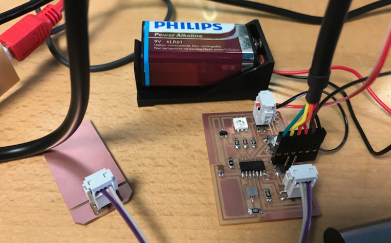
After I programmed it I disconnected the fabISP and connected the black cable to the 6 pin header. The orange wire goes to TX and the red one to RX.
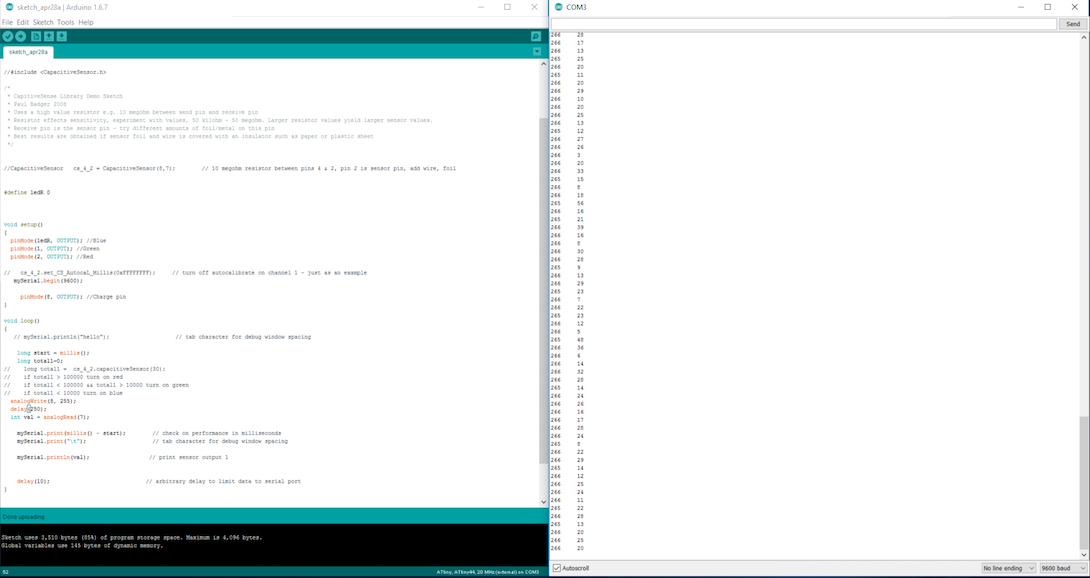
To see the number when it sensor something you go to Tools-->Serial Monitor and the window to the right should appear.
TEST WITH ARDUINO
I also made a touchpad test with arduino that I found here. The code can be downloaded in the link and more details. The images below shows how it should be connected.
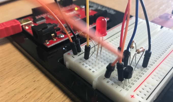
The red cable is connected to the touchpad.
The video shows how it works.
Touchpad Test from BirkirThor on Vimeo.
SOUND SENSOR BOARD
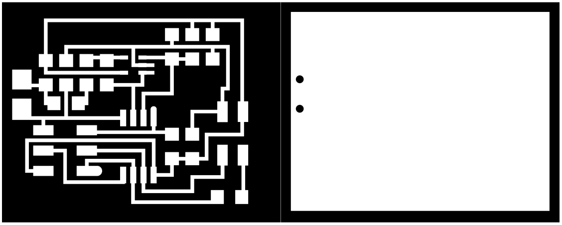
This is a sound sensor board. It's the same board that Neil have in Input Devices except I changed it a little. Instead of using the FTDI cable I put 4 pin header instead, GND, VCC, TX and RX. I added a 10K resistor between TX and the PB1 pin on the ATtiny45. I changed it in Photoshop, because I only exchanged the FTDI to 4 pin header and adding one resistor and holes where the mic is. You can see Neils board here.
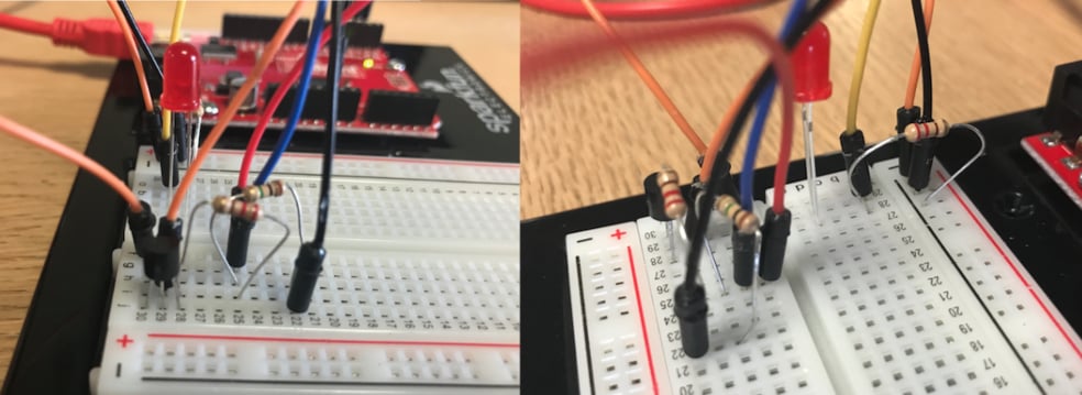
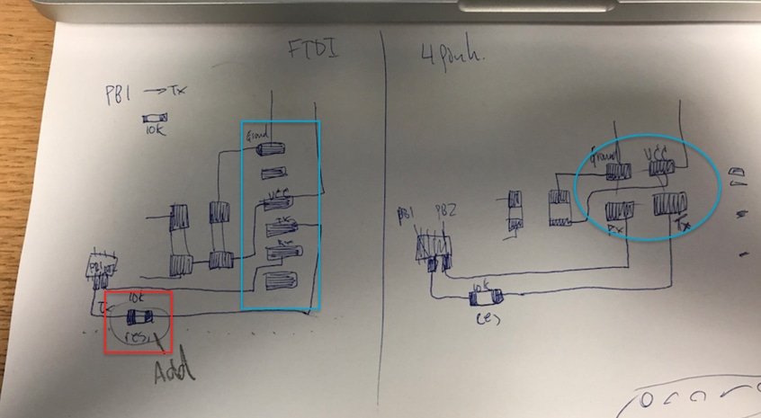
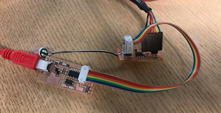
Here you can see how I changed the cables. The one to the left is with the FTDI cable and the one to the right is with the 4 pin connector. In the red circle is the 10 K resistor I added. In the FTDI (blue box) you can see that there are two pins not in use, so the other four are GND, VCC, TX and RX which are also on the 4 pin connector (see in the blue circle). I was going to put the plus and minus (the mic) wires threw the board and solder them, so I made a holes in the interior file like you can see from the image above.
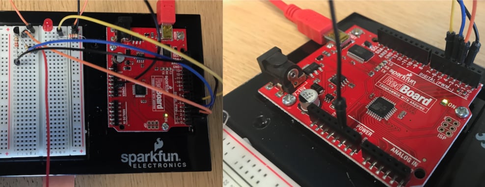
I soldered the board and connected it with a FabISP programmer that also power the board. I am using the TX and RX on the FTDI cable to see the values in serial monitor, the yellow wire goes to TX and the orange wire goes to RX.
This is the sound sensor code I made in Arduino with a help from my Fab Academy Instructor Bas Withagen. The sound sensor board picks up low frequencies. Threshold is a line that if certain number reaches the threshold or goes over it, something happens. In my case it changes the color of the LEDs each time the value is equal or more.
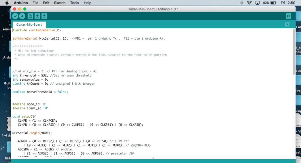
This is an example of my sound sensor board. I have opened a serial monitor window to see the value that the mic is sensing. When the bass starts the values goes up. First I write big M in and the board returns small m, which is the id of this board, I will later get more into networking and communications in week 15. I have to type small m in serial monitor to see the value. The code can be downloaded in Download Files.
Mic from BirkirThor on Vimeo.
TOUCHPAD TEST FOR MY FINAL PROJECT
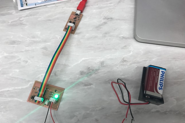
In this video I am showing the values coming from the touchpad when I touch it. I am using the master board which is connected to the FTDI cable and powered with a 9V battery. I took the red wire (VCC) of the FTDI cable or else I would burn the 5V regulator. This is a test that I would develop and have in my final project. The idea is when I touch the copper plate the value goes up and when it goes over certain threshold it turns on a pin on the ATMega which gives power to the guitar through two wires (4 pin header) and therefore changes the plus to minus and mutes the sound.
On the video below the values change when I touch the copper plate.
Touchpad_Test from BirkirThor on Vimeo.
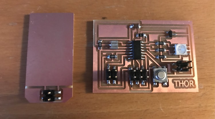
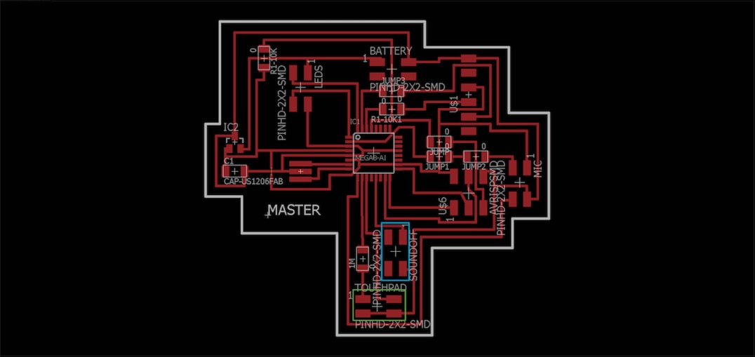
This is the master board. In the green box is the 4 pin connector that is connect to the copper plate (touchpad). One pin is TX (the one with the 1 M ohm reistor between) and the other one is RX, the two others are ground.
In the blue box (I call it sound off) is the 4 pin connector that connects to the pickup and the output jack on the guitar. On pin is ground and the other one is connected to one pin (PB1) on the ATMega.
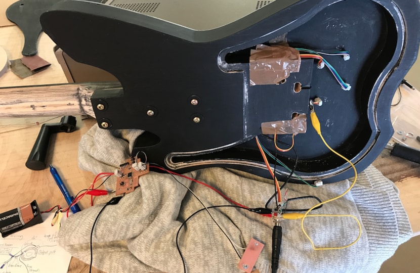
This is how the connections looked like when I was testing it. The sound off/4 pin connector is connected to the PB1 pin on the ATMega, it goes to the black wire on the output jack (-) and the ground pin goes to the ground on the guitar (+) which is on the output jack.
I was having some troubles grounding the guitar so I put an extra ground to the guitar body itself which is the yellow wire. It's done by putting a screw on the body and wire from the ground on the output jack on the screw. Unfortunately it didn't fix the problem.
In this video I am testing the touchpad/copper plate. I have every thing connected and when I play the guitar and touch the copper plate the sound goes off. There is a high frequency clicking sound when I touch the copper plate, but it works. Also it takes the sound few seconds to com back on after I have muted it. I have to develop this and debug to have this work as I want.
The Arduino code can be downloaded below or in Download Files.
Touchpad_mute pin from BirkirThor on Vimeo.
RELATED LINKS
DOWNLOAD FILES
Traces PNG - Right click to download
Cut PNG - Right click to download
Arduino Touchpad Sensor - Right click to download
Arduino RGB Changing Colors - Right click to download
Touchpad Traces - Right click to download
Touchpad Cut - Right click to download
Touchpad Schematic - Right click to download
Touchpad brd - Right click to download
HAVE QUESTIONS?
Contact me!
Höfn, Iceland
Email: birkirthorhauksson@gmail.com
Swing by for a cup of , or send me a message :)