First stage extruder - the syringe
First step by developing the first stage was to get a syringe that can hold enough material and is easy to buy everywhere.
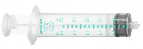
I choosed a "perfusor" syringe from "Braun".
This syringe is used in perfusors, medical machines that can give a constant flow of a medicine over a long time to a patient. It can hold about 50ml material and has a indentation for a mechanical actuator. Pretty exact what I want to do...
At the lower end the syringe has thread to connect a smal hose that you can also buy in every pharmacy.
Costs for syringe and hose: under 2$
LINK
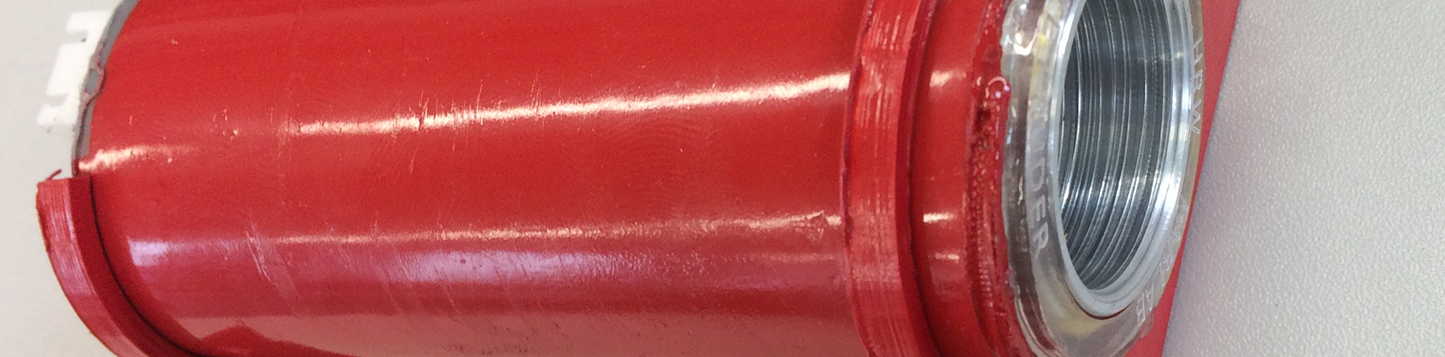
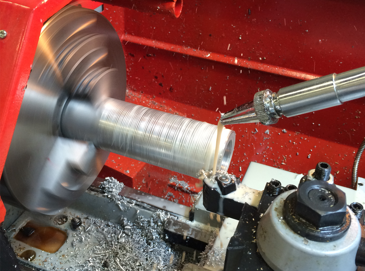
For the heater I get some aluminum-rod with a diameter of 50mm.
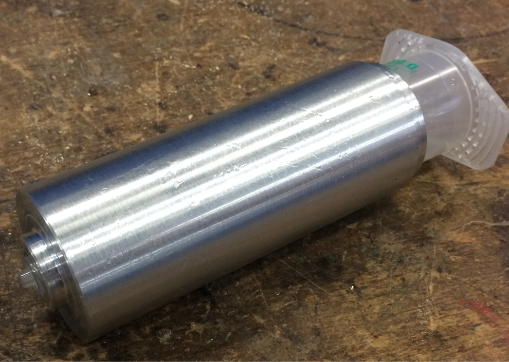
On the lathe I made a slim-fit case for the syringe that fits exactly so the heat is transferred with a high efficiency into the syringe.
Next I wrapped some 0,8mm kanthal-wire around the aluminum case. Kanthal-wire has a very constant resistance by around 2Ohm per meter. If you let flow a current thru the wire it gets hot. A perfect heater...
The kanthal-wire is not isolated, so I put a layer of kapton-tape around the aluminum first. Kapton-tape can resist temperatures up to 350 degree Celsius...
To fixture the wire I wrapped a second layer tape around the hole construction.

Heated elements a a big risk for burning your fingers, so I put the aluminum case into a plastic-pipe. On the upper end the case is hold by a laser-cutted acryl (also engraved the name of the extruder for making it nice)...
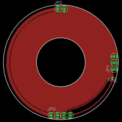
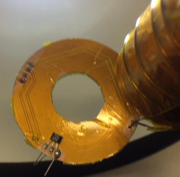
On the lower end it is hold by a circuit board. The idea was to put a connector on the board and connect the heater and a temperature-sensor directly to the board. This way the assembly would be much easier.
Didn't worked...
If you wrap a relative thick wire around a big aluminum block it can absorb a LOT of heating-energy. Good for a heater, bad for a solder iron...
No chance to solder the kanthal to the board, so I improvised with some clamps.
Still on the board lies a temperature sensor. It is directly connected to the aluminum with a small amount of thermal compound. The sensor it self is a TD5A thermistor. This device is a temperature controlled resistor. At 20 degrees it has about 2k ohm, the hotter it gets, the higher gets the resistance. You can measure this by a simple voltage-divider. Not very exact, but for 0.5 degree it is just fine.
Therefore the TD5A is connected to ground on one pin, on the other to a 2k-resistor connected to 5V. Between the two components is a sense-wire for the electronics.
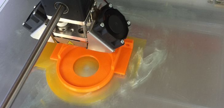
The plastic-pipes outside is hold on the upper and the lower side by two printed plastic-parts so it can be screwed to a wooden plate.
The upper holder has also some holes to hold the geared DC-motor.
The motor is connected by a selfmade coupling to a trapezoidal screw. On the screw runs a printed thread that fits into the upper end of the syringe.
I never printed a thread before, but it worked very well.
Some tips for this: use fusion360, not solidworks. Fusion lets you sketch a thread very easy. Next you have to check "modeled". After this you can export a stl file directly to your printer.
After the print the thread was a little bit to small, the screw runs not very easily in the thread.
To fix this: get some battery drill and turn the screw some minutes in the thread until it gets smoothie

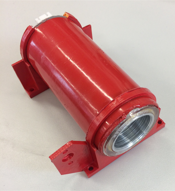
And this is the first stage completly assembled without the screw:
Here you can download all sketches (SolidWorks, Fusion360, STL):
extruder_1.zip