
Week 8: Embedded Programming - Bringing FabPIC to life
This week we will bring our Fab-Pic from two weeks ago to life.
What we will need for this:
As you can see, the toolchain is available for Windows, Mac and Linux. MPLAB itself is based on eclipse.
Download and install it in the given order.
When everything is succesfull installed, we are ready for our first program.
Open MPLAB and start a new project:
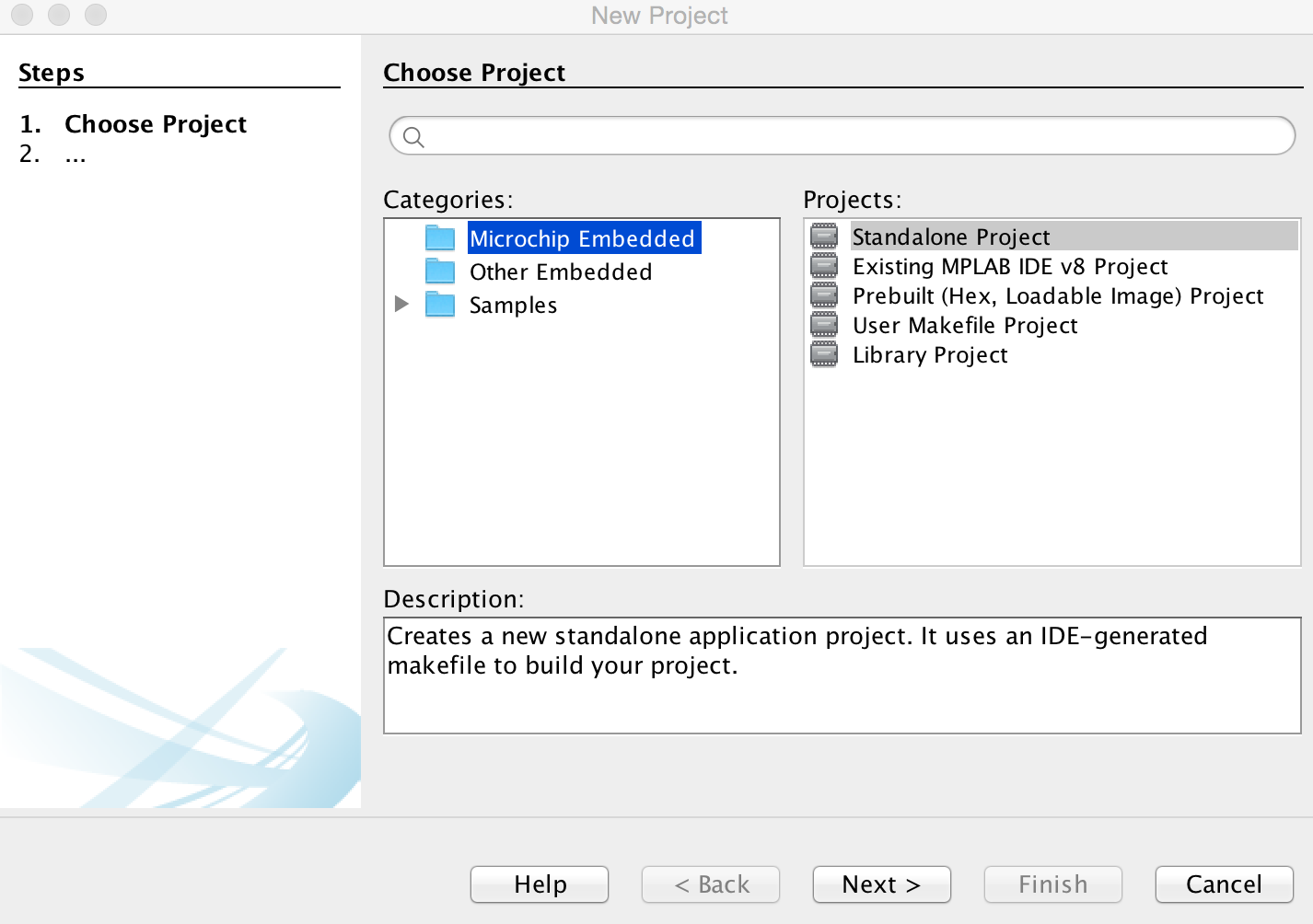
Select a new standalone project

Select your PIC, in our case the 18f26k80
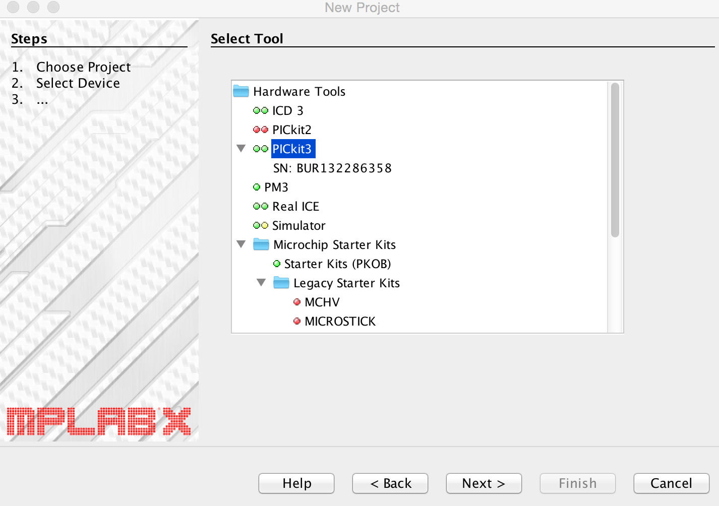
Select your programer and debug-tool, i use the pickit 3
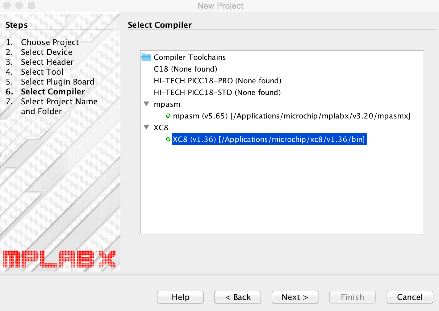
Select the XC8 Compiler
No screenshot, but do the following: on the left side, right-click on "Source-Files" -> New -> main.c. Then:
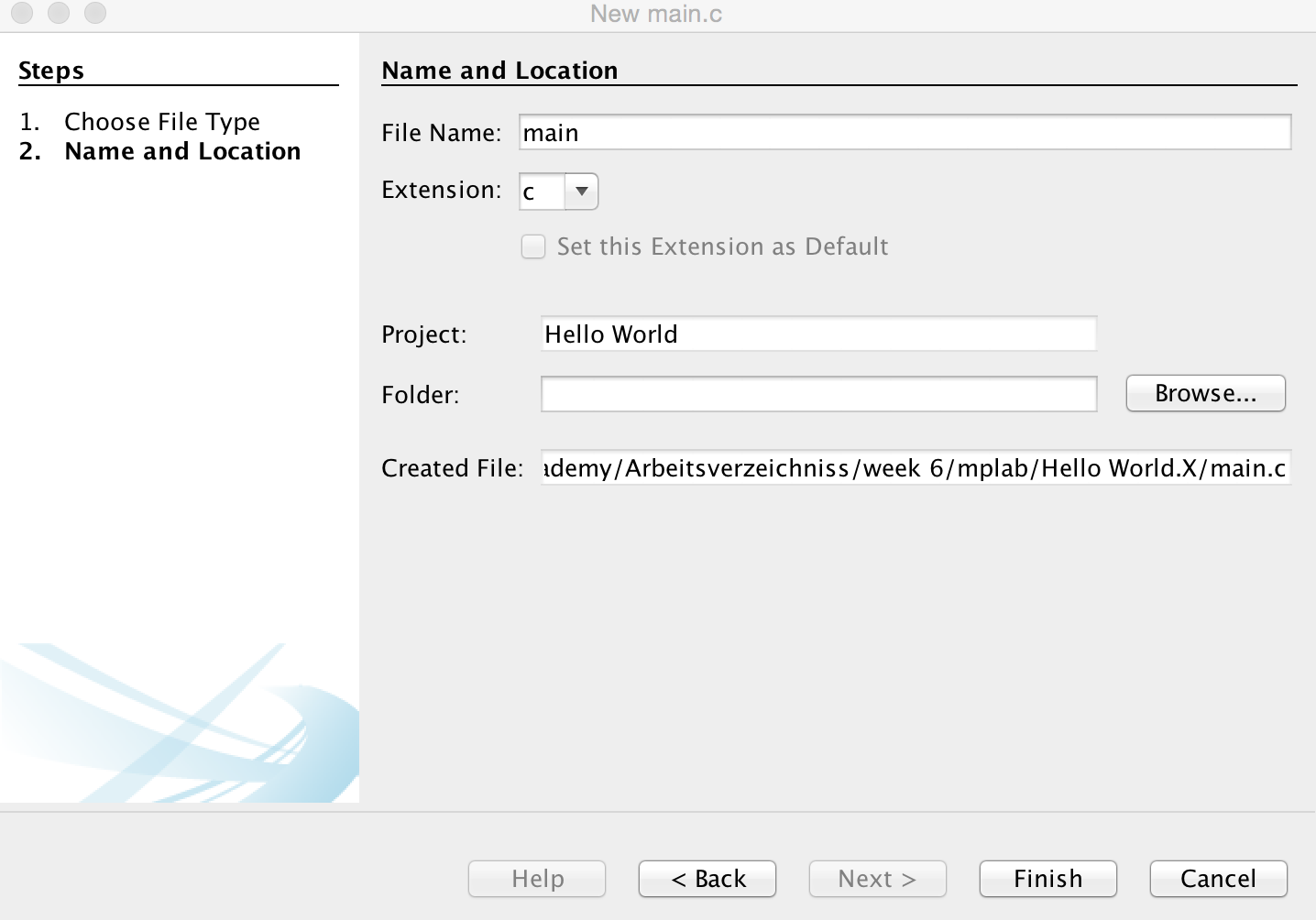
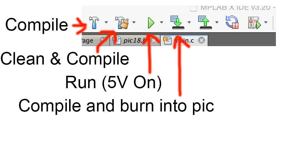
Now you see your main.c, the main file for our code. Before i explain my basic hello-world, here is the main tool bar you have to use:
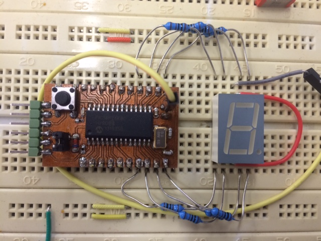
For the Hello-World example i connected a Kinbright SC56-11EWA numeric display to the port C of the Fab-Pic with some 1k-resistors.
Let´s start with the code:
#include <xc.h>

#include <plib.h>


#define _XTAL_FREQ 32000000   //Only used by the delay-functions

#define onboard_led  PORTBbits.RB7

#define onboard_button  PORTBbits.RB6


#define led_seg_e  PORTCbits.RC0

#define led_seg_d  PORTCbits.RC1

#define led_seg_c  PORTCbits.RC2

#define led_seg_dp PORTCbits.RC3

#define led_seg_b  PORTCbits.RC4

#define led_seg_a  PORTCbits.RC5

#define led_seg_f  PORTCbits.RC6

#define led_seg_g  PORTCbits.RC7
First we include the xc.h and the plib. These files are needed by the compiler for some symbols and so on.
Next we make some defines: _XTAL_FREQ is only used by the delay-functions of the PLIB, so just define it with your speed. The other defines are just for the readability of the code. In fact, these are not even used in the hello-world-example ;)
The next few lines are very important, here we set the basic-flags for our controller to run:
#pragma config FOSC = HS1    //extern oszilator 4-16mhz

#pragma config PLLCFG = ON   //PLL enable, CPU=32 MHz

#pragma config PWRTEN = ON   //PowerOnTimer on

#pragma config WDTEN = OFF   //Watchdog Timer off

#pragma config XINST = OFF   //Extended Instruction Set off, no support by free compiler

#pragma config SOSCSEL = DIG //PORTC.0 and PORTC.1 digital I/O, not second oszilator
The configs are explained in the datasheet, read there if you want more infos then the comments
The delay function has a big disadvantage: due to its internal structure the delay_ms can only handle breaks of about 37ms. Short break...
I want a break of one second at some points in the Code, so i wrote a little sub-routine:
  void delay_one_second (void)    //make a break for one second

{

    int i;

    for(i=0; i<50; i++) {

     __delay_ms(20);   //inline delay max. 20ms, so repeat it 50 times for one second

    }

    return;

}
In a second sub-routine the numeric display is actuated. How this works in detail i will explain in the output-assingment.
What you now need to know:
PORTC = 0b01010101; sets the level of all pins of port c.
  void display(char x)

{

    switch (x){

        case '1': PORTC = 0b00010100; break;

        case '2': PORTC = 0b10110011; break;

        case '0': PORTC = 0b01110111; break;

        case '6': PORTC = 0b11100111; break;

        case 'A': PORTC = 0b11110101; break;

        case 'B': PORTC = 0b11000111; break;

        case 'C': PORTC = 0b10000011; break;

        case 'D': PORTC = 0b10010111; break;

        case 'E': PORTC = 0b11100011; break;

        case 'F': PORTC = 0b11100001; break;

        case 'M': PORTC = 0b00100101; break;

        case 'Y': PORTC = 0b11010110; break;

        case ' ': PORTC = 0b00000000; break;

        default: return;

        }

    return;

}
After the two sub-routines followes the main-routine:
  void main(void) {

    //setup Pull-Up for onboard button

    INTCON2bits.RBPU = 0;

    WPUBbits.WPUB6 = 1;


    //config outputs

    LATBbits.LATB7 = 0;TRISBbits.TRISB7 = 0; //onboard_led


    //Kingbright SC56-11EWA at port c

    LATCbits.LATC0 = 0;TRISCbits.TRISC0 = 0; //element e

    LATCbits.LATC1 = 0;TRISCbits.TRISC1 = 0; //element d

    LATCbits.LATC2 = 0;TRISCbits.TRISC2 = 0; //element c

    LATCbits.LATC3 = 0;TRISCbits.TRISC3 = 0; //element DP

    LATCbits.LATC4 = 0;TRISCbits.TRISC4 = 0; //element b

    LATCbits.LATC5 = 0;TRISCbits.TRISC5 = 0; //element a

    LATCbits.LATC6 = 0;TRISCbits.TRISC6 = 0; //element f

    LATCbits.LATC7 = 0;TRISCbits.TRISC7 = 0; //element g


     //config inputs

    LATBbits.LATB6 = 0;TRISBbits.TRISB6 = 1; //onboard_button


    while(1){

        delay_one_second();

        display ('F'); delay_one_second();

        display ('A'); delay_one_second();

        display ('B'); delay_one_second();

        display ('A'); delay_one_second();

        display ('C'); delay_one_second();

        display ('A'); delay_one_second();

        display ('D'); delay_one_second();

        display ('E'); delay_one_second();

        display ('M'); delay_one_second();

        display ('Y'); delay_one_second();

        display (' '); delay_one_second();

        display ('2'); delay_one_second();

        display ('0'); delay_one_second();

        display ('1'); delay_one_second();

        display ('6'); delay_one_second();

        display (' '); delay_one_second();

    }

    return;

}
Let´s discuss this line by line... The Fab-Pic version i use is a V0.9. In this design there is no extern Pull-Up for the Button on the Fab-Pic itself, so i use the internal ones. Those are enabled by
  INTCON2bits.RBPU = 0;

  WPUBbits.WPUB6 = 1;
After this we will tell the pic which pins are outputs and which are inputs. These are controlled by the "TRIS"-Register. Before setting the TRIS we will clear the latch of each pin by
LATCbits.LATC7 = 0;. A 0 in the TRIS will make the pin an output, a 1 an input:
TRISCbits.TRISC7 = 0;The hello-world will just give out some chars on the numeric display, therefore the whole program loops endless in a while-loop. Inside the loop the display-subroutine with the char is started, followed by a delay of one second:
display ('F'); delay_one_second();
After compiling and burn into the pic we can see the chars on the Display:
And voila, our first program with some output on the fab-pic!
If you´re interessted in the files, here is the MPLAB-Project:
So, have fun!