Week 7: Computer-Controlled Machining
Assignment:
- Make something big (on a CNC machine)
This week we are working with Shopbot which is a 3-axis machine with 4feet x 8 feet bed size capable
of working with plywood,timber etc.
ShopBot
A ShopBot controlled by personal computer is capable to perform precision, large-format, cutting, drilling, machining, and shaping in many materials. We can go for a varity of designs which is hard to be done manually in shopbot.

Bit Selection
Lets start with the Bits used in Shopbot.I have used the document which I got from here .
Bit material: Router bits used in Shopbot are made from a variety of materials such as solid carbide, carbide-tipped steel, and high-speed steel.
Flute type: There are four basic flute types: Straight, spiral up-cut, spiral down-cut, and compression.

Straight flute :maintain a Good edge quality after the process.here we will be getting a moderate chip clearance and are ideal for general purpose cutting
Spiral up-cut:It may chip away top face,maintaining bottom face in a good quality..Excels at clearing chips and dissipating heat, especially with “o-flute” bits Upwards force may cause part lifting. I can be used when for working with plastics,aluminum,etc where heat buildup is a concern
Spiral down- cut Best edge quality on top face, may chip or fray bottom face when through-cutting May compact chips in a groove Downwards force may help with cutting thin sheets.Ideal used for plywood and laminates (pocketing)
Compression:Clean edge on both top and bottom face Designed to cut veneered or laminated materials at full depth in one pass Ideal for: plywood and laminates (profile cutting)
Number of flutes: The number of flutes on a bit is essential to calculating proper feed and speed rates. For most applications you can use a bit with 1, 2, or 3 flutes, but you must adjust your feed rates and RPM accordingly to maintain proper chip load.
End shape: Straight and up-spiral bits come in a variety of end shapes. Square ends are most common, and are a good choice for creating pockets and grooves, profile cutting, simple lettering, and drilling operations. Ball (or rounded) ends are best for 3D carving. V-carve bits are often used to create complex letters for sign making. They can also be used to chamfer edges and create countersinks for screw holes.
Calculating feeds/speed with Chip Load: Chip load refers to the actual thickness of the chip cut by each revolution of the cutter. It is the measurement that all feed/speed calculations are based on. A spinning bit generates friction and heat as it moves through the material, and part of this heat is pulled away by the flying chips. A larger chip load pulls away more heat, but also puts more stress on the cutter. Each material has its own ideal chip load range that balances heat dissipation with cutter stress.

An end mill has cutting flutes that extend across the bottom (end) of the bit. It is designed for plungecutting as well as lateral cutting. “Square-end” is simply a description of end shape. Square-end bits are not always end mills, and end mills do not always have square ends.
Chip load :- This is the amount of material that is removed in each chip. The value is approximately = feed rate (inches per minute) / (RPM x number of flutes)
Cut depth :- This is the measure of how deep the end mill should go in each step while milling. To be more clear, understand that these machines mill step by step, they go to a certain depth first and do the entire milling once and then move to the next step and repeat till it reaches the point we specify.
Step over :- While milling a pocket, the surface will be divided into spiraling lines through which the end mill travels. While doing this the step over determines how much the adjacent path make the end mill cut to overlap each other. Usually we use it at 50%, ie the adjacent end mill cuts will overlap 50%, which gives a better finish.
bit size used my me is 6mm
Collet
An external collet is a sleeve with a (normally) cylindrical inner surface and a conical outer surface. The collet can be squeezed against a matching taper such that its inner surface contracts to a slightly smaller diameter, squeezing the tool or workpiece whose secure holding is desired. Orient the collet and nut as shown at the below left and press them together until the collet clicks into the nut. This will form the collet nut assembly. This assembly will now be inserted into the spindle in the orientation shown below. Tighten the nut a few turns onto the spindle without compressing the collet to hold the assembly in place. Now you can insert your bit and hand tighten the nut until it holds the bit securely. At this point use the provided wrenches to tighten to the appropriate specification for your spindle.

ER25 series collets have a capacity of .015-.630 inches. Each ER25 collet has a range of .039 inches(1mm). ER25 Collets .094 and smaller have a range of only .015 inches. The size indicated on the collet is the largest size it can hold .


Positioning the bit
The first step is to position the bit in 0,0,0 in the X, Y, and Z axis . There is a built-in method for setting the Z axis, using a metal plate and clip and running a specific program on the ShopBot, but there is no such program for setting the X and Y, requiring the user to manually position the bit.

The x and y axis movement can be controlled by the user interface given in the system,after the correct position is obtained set the x and y axis value to zero.

Pull the Zeroing Plate and Alligator Clip off of the router
-Attach the Alligator Clip to the Zeroing Screw on the CNC Router

-Place the Zeroing Plate with a direct vertical path below the router bit
-Call C2 on the control panel in Shopbot 3
-A pop-up will appear in ShopBot 3 that asks you to make sure that the Alligator Clip and Plate are in position. You will need to agree to this for the zeroing process to begin.
-Watch the Zeroing process to ensure the bit will hit the plate

-Another pop-up will appear on the screen asking you to return the Alligator Clip and Plate.
-The router should stay at a safe height above the table after being zeroed, however, if need be, raise the router safely above the table
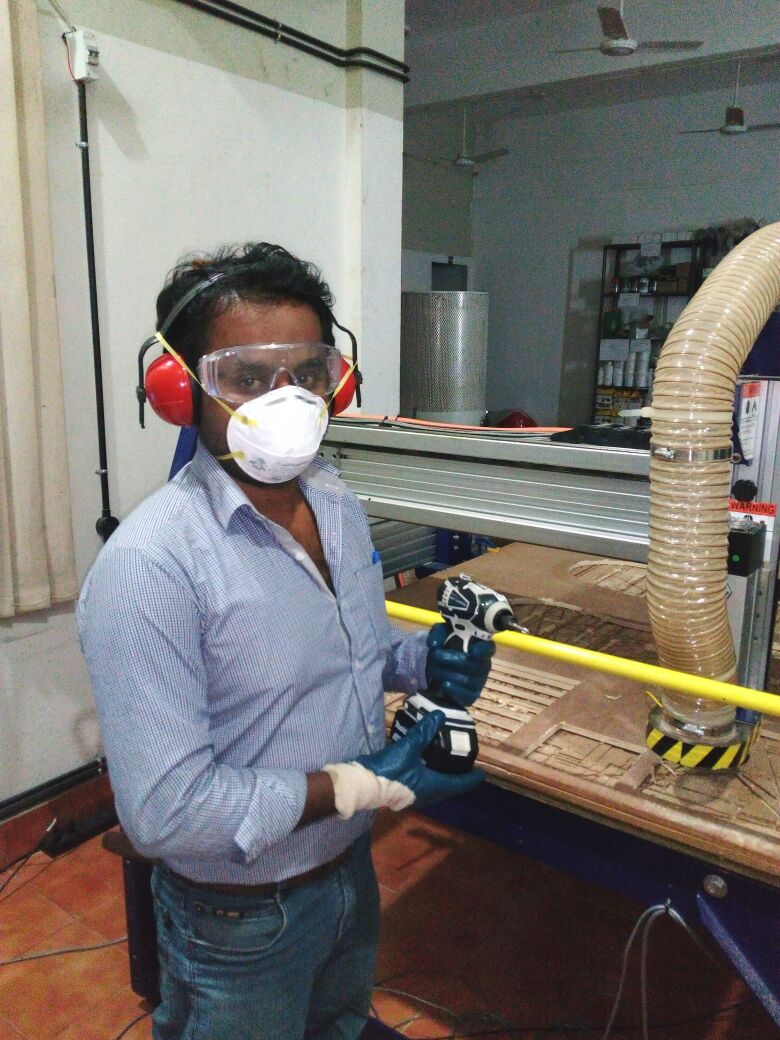
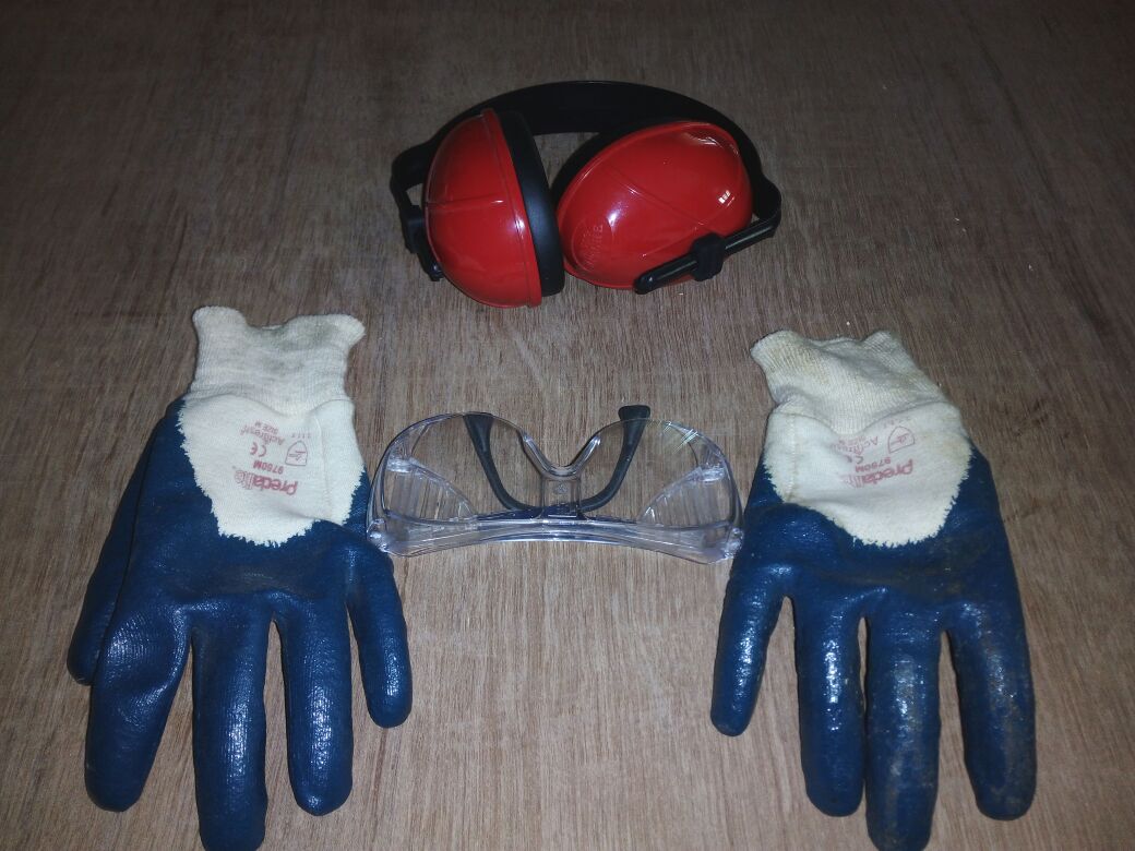
Accessories used and Safety measures
|
|
|---|---|
|
|
Safety should be given prime importance
|
|
|---|
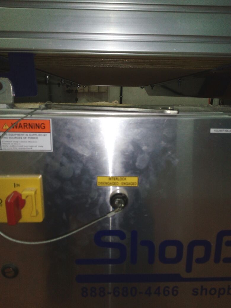
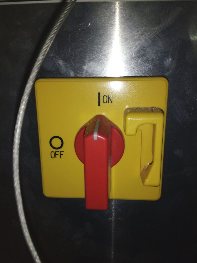
In order to turn on the machine Insert the key attached to the collet wrench into the keyhole on the control box. Turn on the control box with the big red switch.
|
|
|---|
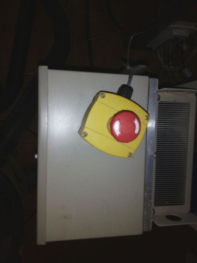
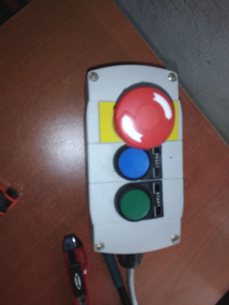
The machine won’t talk to the computer until we reset the drivers. This can be accomplished by using the yellow control box with a big red button, a blue and a green button. Press the blue button.
note:If any thing went wrong during the Shopbot working use shift key in the keyboard to pause the process
Designing and working with ShopBot
I don't have a shelf in my home,so I prefer to make a shelf.I could design a pressfit model.
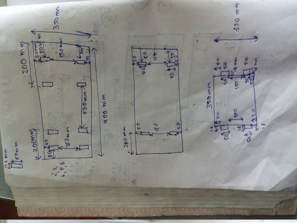
Using the information from the test cut ,I used 17.6mm for designing the shelf which uses plywood of size 18mm.

I used Rhino for designing my shelf.


My shelf in a 3d view is given below
For cutting purpose we have to calculate the bed area,which is described at the end of this documentation.After arranging select the area in side the rhino and export as .dxf file and use this file for further workin the shopbot.
I opened my .dxf file in VCarve Pro which provide a powerful but intuitive software solution for cutting parts on a CNC Router.
Once the file is imported, place it in a location that will use the material efficiently . Next ensure you have no “open vectors” for each part. An “open vector” means that there are lines that are not connected, open vectors cause the bit to randomly cut on different sides of the line.

Images taken from here
I selected profile machining for my work
Select the type of toolpath needed for the job
1. Set start depth to zero
2. Set cut depth to slightly more (about .1) than the thickness of the material. If cutting a pocket tool path set it to exactly the depth you wish to cut.
A good docuentation is given in this link ,this will provide all the steps required for working with the software

Tool selection

editing the tool

Selecting the number of passes ,we should not use 1 because more heat will be produced 4 or 5 will be a better option. Pass depth should not be greater than the tool diameter.

3d view

vector path

Shopbot doing the task ,the xyz setting has to be done as told previously before the process starts.

finally the shopbot completed its task
|
|
|---|
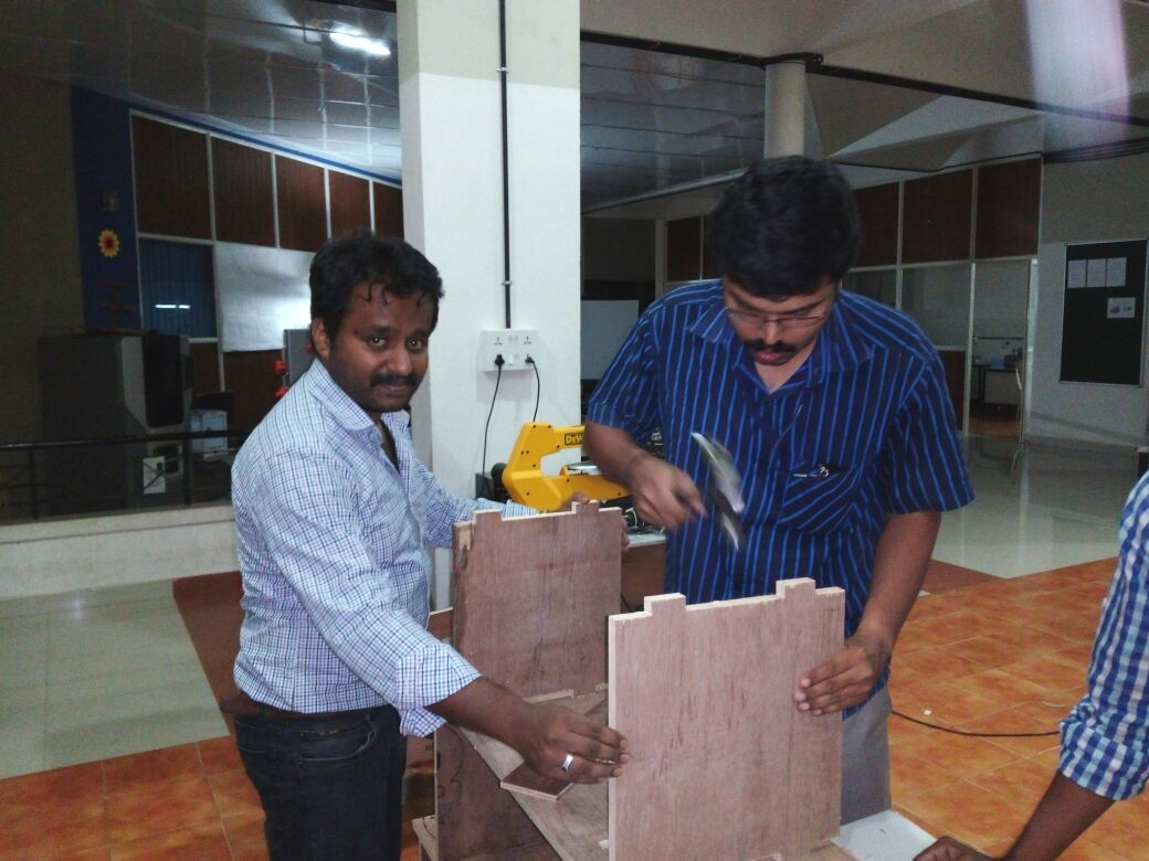
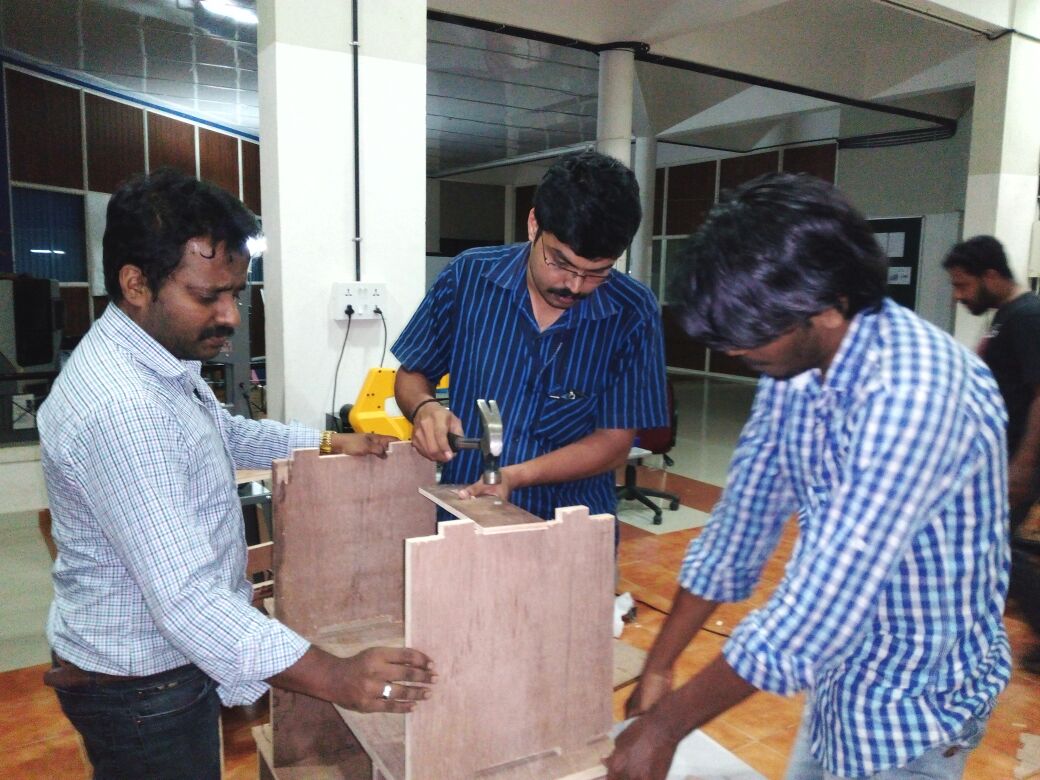
Press fit ,understood the meaning in real world

my final shelf is ready
I designed the shelf in rhino and design file is here
The problems faced
The bed size which I used for calculations is 8 feet* 4 feet,ie 2438.4 mm *1219.2 mm.I given an extra 30mm in all side for setting the bed area . Therefore the final alowed area is only 2378 mm *1159 mm.

Even though I have provided extra area ,the bit moved out of track ,so I losed 10mm side ,which was finally adjusted with a long 10mm width plywood peice.
In between the process the dust is not being taken properly,the reason is that there was a bend in the tube.