Week 9:Mechanical Design
Assignment:
- Make a machine, including the end effector, build the passive parts and operate it manually
We decided to make a Robotic arms that moves along a guide rail.We are a group of 9 members.My responsibility is to Load test the machine.I used arduino for testing.
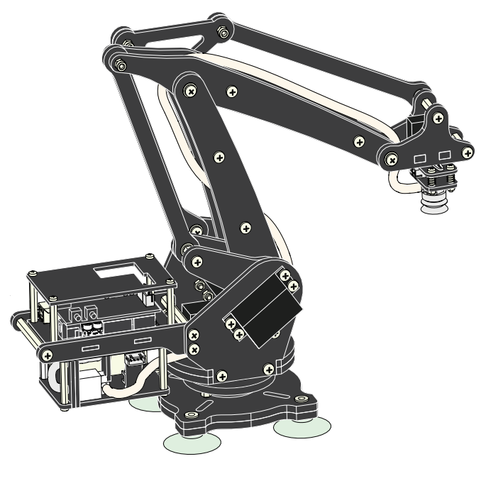
FAB-ARM
FAB ARM is a replecated form of UARM.Even though it is replecated,the effort we made in doing is big.
|
|---|
U-ARM |
Group members
1) Renjith M S
2) Syed junaid Ahmed
3) Ganadev Prajapathy
4) Jithesh Gopal
5) Rahul S rajan
6) Sachin Salim
7) Ajith Kumar m g
8) Sreejith Mohanan
9) Jim J seelan
My contribution
In our project we are a group of 9 members in which some collected the parts,some where engaged in part assembly and some in designing the rail. I took the responsibility to automate the KARM using Servo motor ,so that we could anylise the design,ie whether it functions as UARM.
SERVO MOTOR
In our LAB we have HK15138 analog servomotor.We have doubt on wether it is possible to use it in our project.From the link it is clear that the torque is 4.3 kg at 6 v,so we thought of testing.
There are some special types of application of electrical motor where rotation of the motor is required for just a certain angle not continuously for long period of time. For these applications some special types of motor are required with some special arrangement which makes the motor to rotate a certain angle for a given electrical input (signal). For this purpose Servo Motor comes into picture.
This is normally a simple DC motor which is controlled for specific angular rotation with help of additional servomechanism (a typical closed loop feedback control system). It has a rotary actuator that allows for precise control of angular position, velocity and acceleration with great precision. They are small in size but pack a big punch and are very energy-efficient.
t will only rotate as much we want and then stop and wait for next signal to take further action. This is unlike a normal Electrical DC Motor which starts rotating as and when power is applied to it and the rotation continues until we switch off the power. We cannot control the rotational progress of electrical motor; but we can only control the speed of rotation and can turn it ON and OFF.
A Servo mechanism sometimes shortened to “Servo”, works on mainly three basic components – a controlled device, an output sensor, a feedback system. There is an automatic closed loop control system. Here instead of controlling a device by applying variable input signal, the device is controlled by a feedback signal generated by comparing output signal and reference input signal. When reference input signal or command signal is applied to the system, it is compared with output reference signal of the system produced by output sensor, and a third signal produced by feedback system. This third signal acts as input signal of controlled device. This input signal to the device presents as long as there is a logical difference between reference input signal and output signal of the system. After the device achieves its desired output, there will be no longer logical difference between reference input signal and reference output signal of the system. Then, third signal produced by comparing theses above said signals will not remain enough to operate the device further and to produce further output of the system until the next reference input signal or command signal is applied to the system. Hence the primary task of a servomechanism is to maintain the output of a system at the desired value in the presence of disturbances.

A Servo Motor is basically a DC motor (in some special cases it is AC motor) along with some other special purpose components that make a DC motor a servo. In a servo unit, we can find a small DC motor, a potentiometer, gear arrangement and an intelligent circuitry.As we know, a small DC motor will rotate with high speed but the torque generated by its rotation will not be enough to move even a light load. This is where the gear system inside a servomechanism comes into picture. The gear mechanism will take high input speed of the motor (fast) and at the output, we will get an output speed which is slower than original input speed but more practical and widely applicable.

Now at the initial position of Servo Motor shaft, the position of the potentiometer knob is such that there is no electrical signal generated at the output port of the potentiometer.This output port of the potentiometer is connected with one of the input terminals of the Error detection Amplifier . Now an electrical signal is given to another input terminal of the error detector amplifier.Now difference between these two signals, one comes from potentiometer and another comes from external source, will be amplified in the Error Detection Amplifier and feeds the DC motor.This amplified error signal acts as the input power of the dc motor and the motor starts rotating in desired direction.As the motor shaft progresses the potentiometer knob also rotates as it is coupled with motor shaft with help of gear arrangement.As the position of the potentiometer knob changes there will be an electrical signal produced at the potentiometer port.As the angular position of the potentiometer knob progresses the output or feedback signal increases. After desired angular position of motor shaft the potentiometer knob is reaches at such position the electrical signal generated in the potentiometer becomes same as of external electrical signal given to error detection amplifier.At this condition, there will be no output signal from the Error Detection Amplifier to the motor input as there is no difference between external applied signal and the signal generated at potentiometer.As the input signal to the motor is nil at that position, the motor stops rotating.This is how a simple Servo Motor works.for further details visit link
Troubleshooting the servomotor

The red wire is for power supply ,brown for ground and orange is for control signal.I used arduino for testing the servo motor. The code used is given below.

The servo motor moved from 0 to 180 and moving back
LOAD TESTING
The FAB-ARM which is having 4axis of movement is automated using arduino in 3 axis,with an endeffector .The FAB-ARM made a line in the plane paper.The programis not a big deal.servo is the class containing member functions---attach(), write(), writeMicroseconds(), read(), attached(),and detach() . l1,l2,l3,l4 are objects of class servo where l1,l2,l3 represents the 3 servomotors and l4 is used of temperary settings.The program is not of any logic.Here we are just moving the axis.

Inorder to drive 3 servo motors I used power supply to drive at 6 voltage,so that maximum torque will be obtained.

Finally the Load testing is done.Since we are not having the bearing at the bottom for supporting the FAB-ARM,it is not possible to rotate in the third axis freely.So we hold the FAB-ARM and tested.
Machine Design
Calibration of the FAB ARM

The callibration without mathamatical modelling is a tough task.Me and ajith have done the callibration manually using three 10 k potentiometer,with power supply of 5volt.The 5volt is very important,the arduino is having a 10 bit ADC with the signal range between 0 to 5 volt.The three Servo motors are having different range of operation ie each has different mechanical limits.We identified the mechanical limit manually.

From the above program it is clear that the mechanical limits are set in such a way that ,it has different resolution for each servo,that is to be cleared in the future.Actually in the previous week me,ajith and jithesh had worked with this and drawn some lines.

using the calibration we could determine some points manually and using that we somehow managed to draw the circle.From this operation we got the idea that we have to mathamatically model our FAB ARM before working with that.I am personaly intrested to do the mathamatical modelling,but I have to Go on with my next week.
FAB ARM controlled in the linear axis using GESTALT board
Me and Ajith worked with GESTALT board and got some what confused and It did not worked well,just we could make the connector for the GESTALT and we made connections required between the GESTALT board and the connector .The programs are in Python so no idea,atlast it was cleared by Gunadev (our python specialist) and finaly we could move the stepper motor using GESTALT board and using arduino with same code for semicircle given above we could atlast clean the small area using our CNC.Sregith created the end effectors and we finally completed the cleaning task using FAB ARM controled by both arduino and GESTALT board.
FAB ARM Picking operation
With the new Electomagnetic endeffector created by Srigith we programmed to pick and place the magnetic materials.

Finally we pick and placed ,with out mathamatical modelling instead we used the the same manual calibration process
Download my program files from here