Week 15:Embedded Networking and Communications
Assignment:
- Design and build a wired &/or wireless network connecting at least two processors
This week I decided to implement I2c communication between attiny 45 microcontrollers
Electronic Design
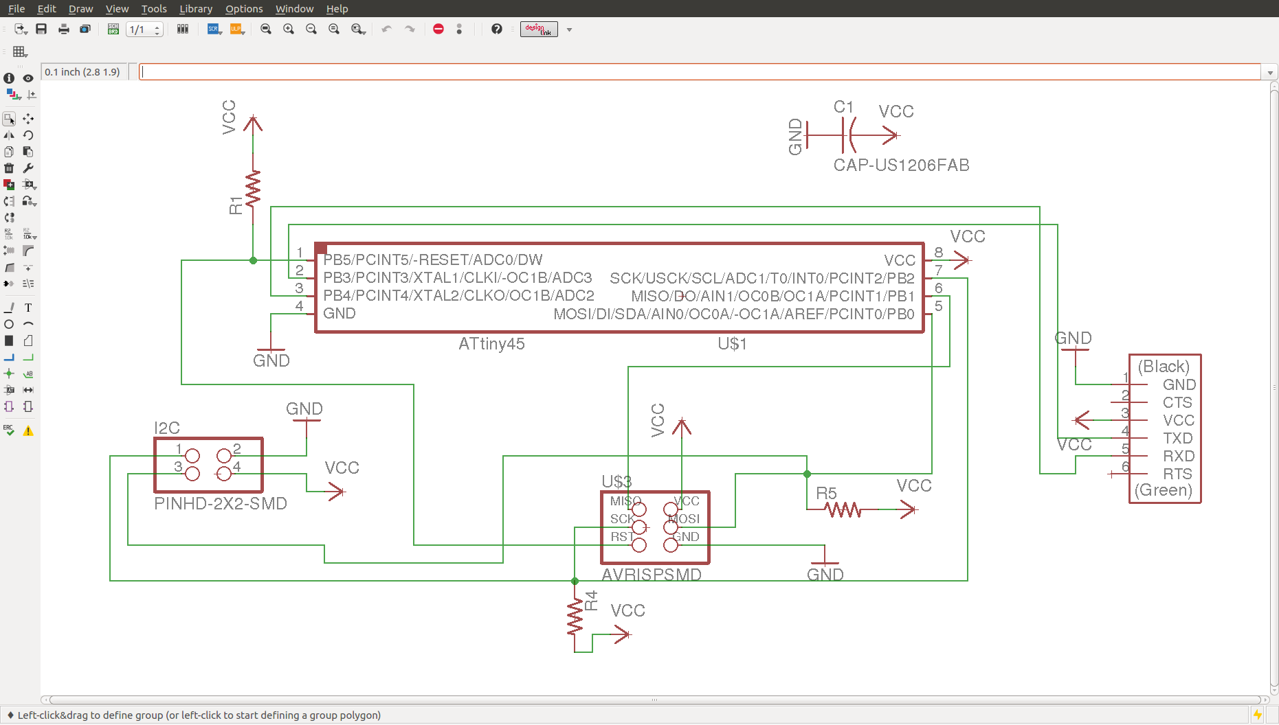
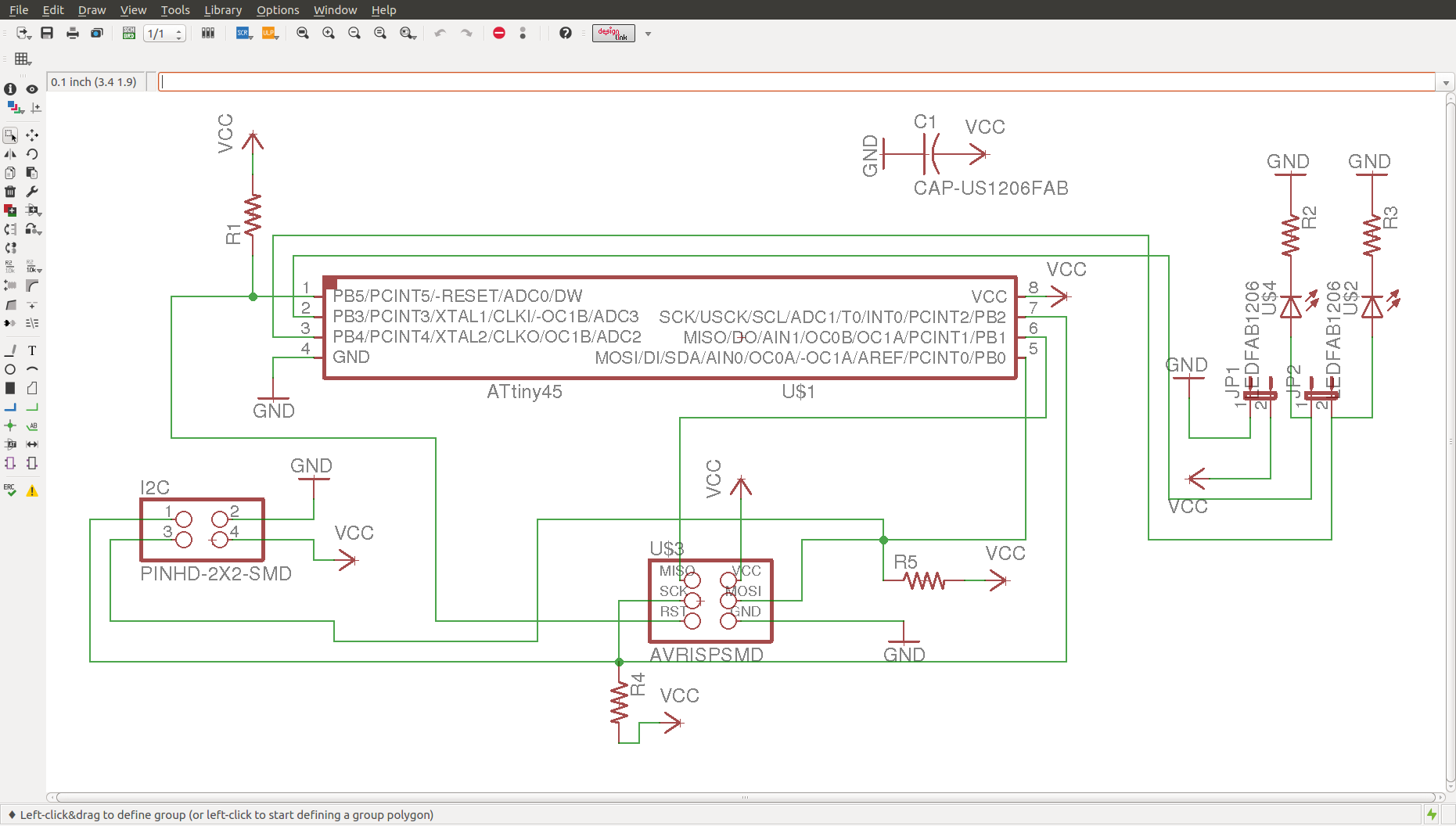
I have designed two board of ATTINY 45 ,one being the master and other one is slave.
The Schematic and board files of master and slave
can be downloaded
from here .
|
|
|---|
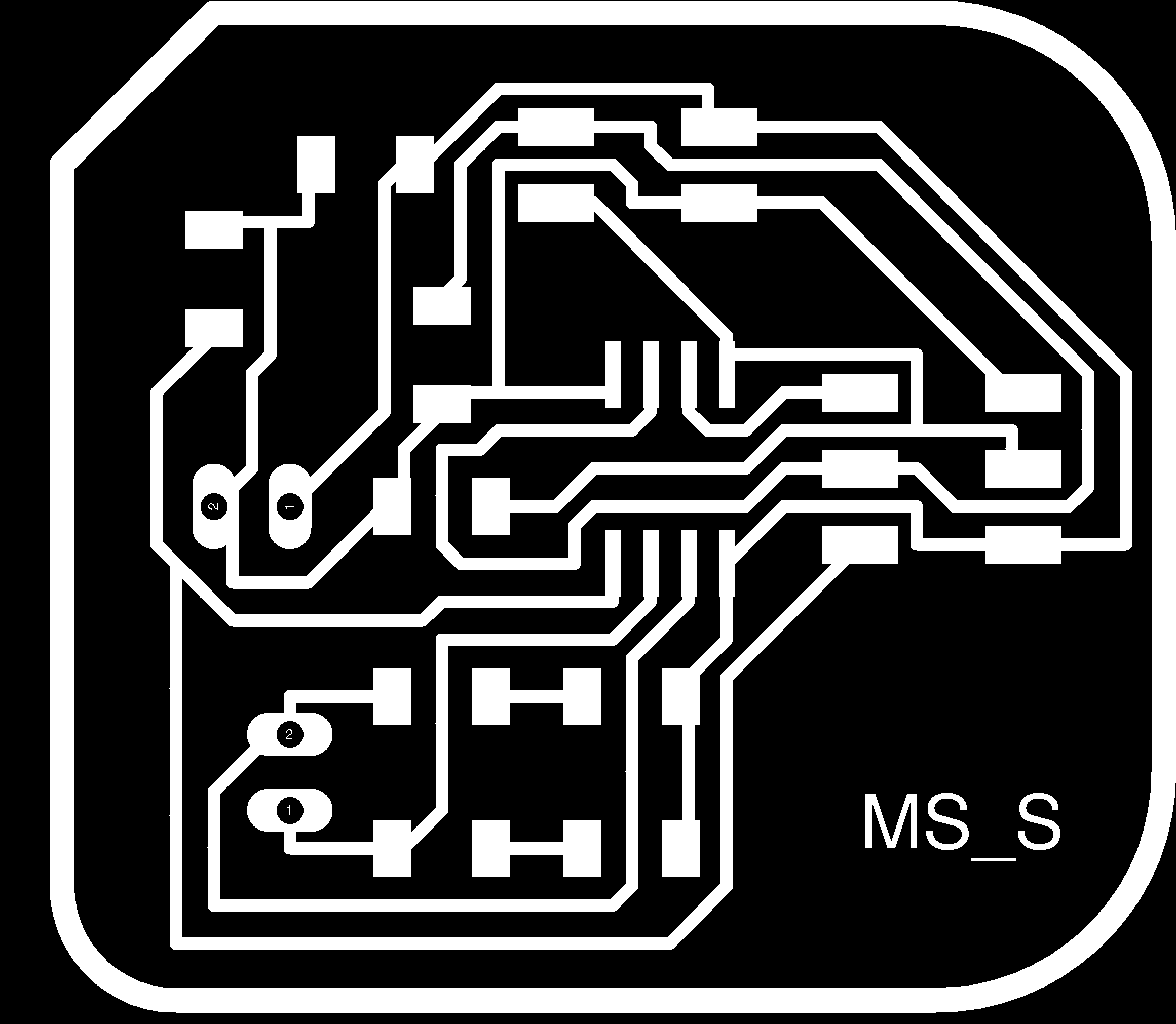
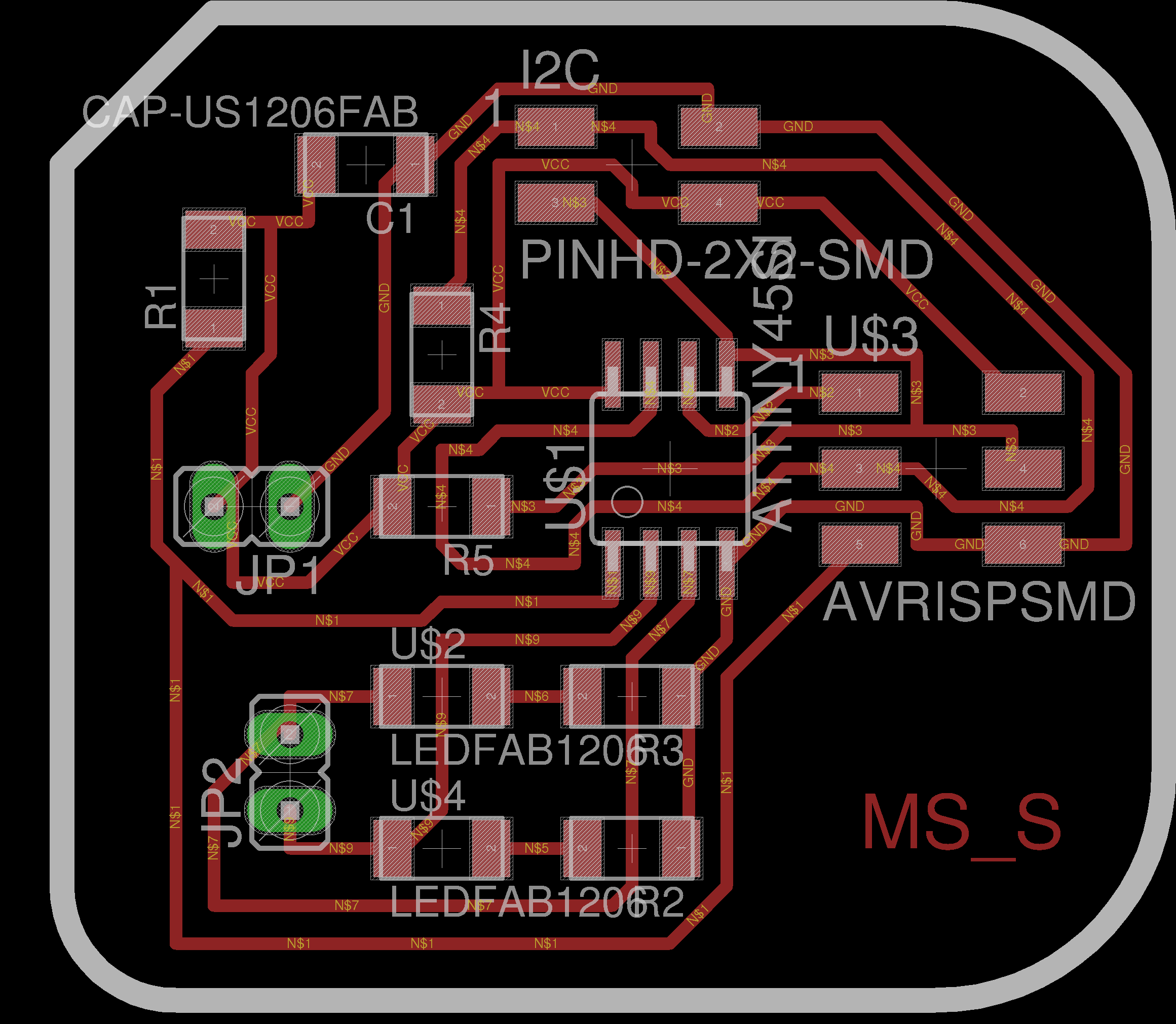
The screenshot for the master and slave is being provided above.From both master and slave it is evident that there is FTDI cable connecting pinout available for master,in slave no such provision.In addition to that in slave two extra led pin out are taken ,this is due to the fact that in slave no FTDI option is available therefore two extra pins are available.
|

|
|
|---|
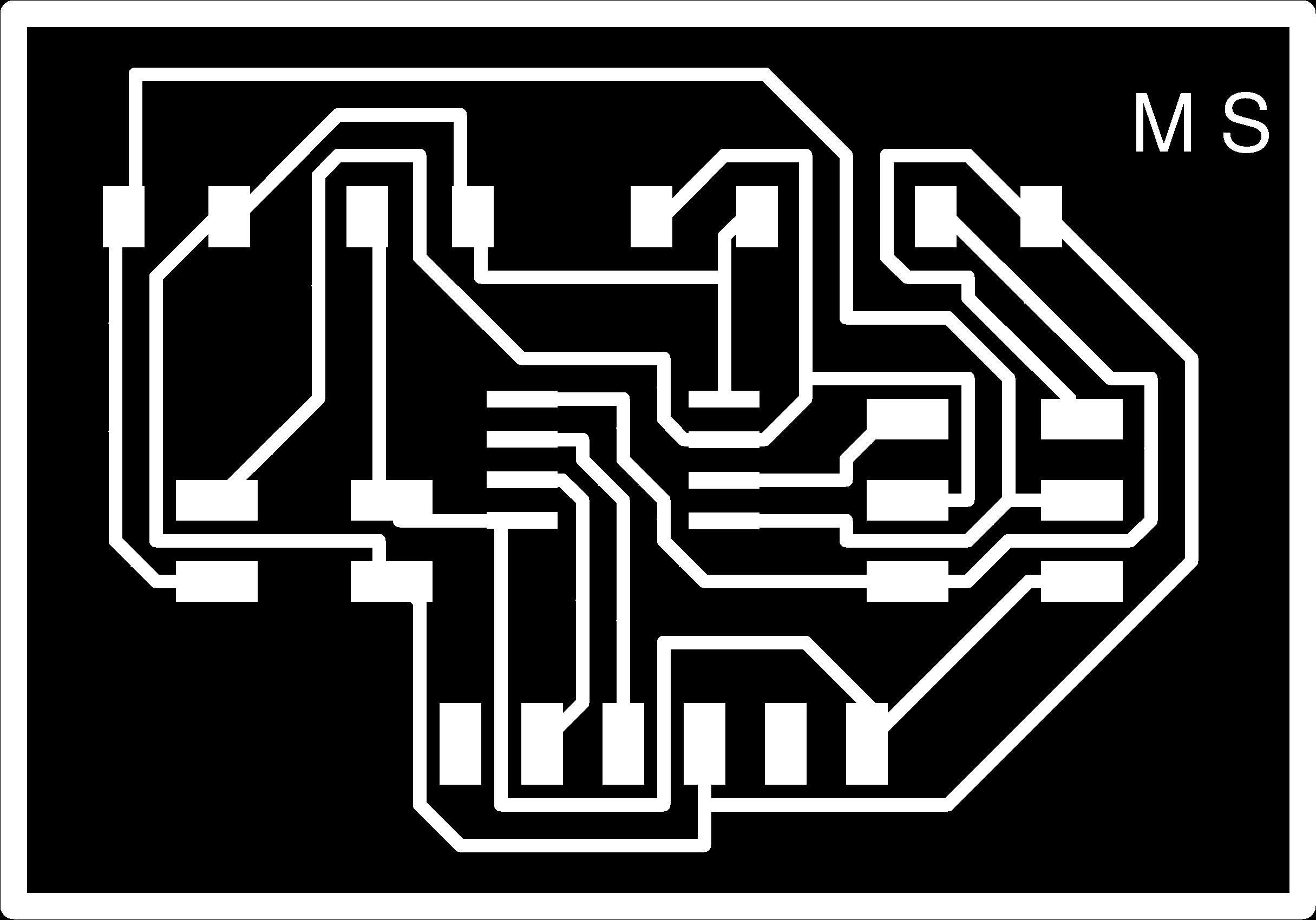
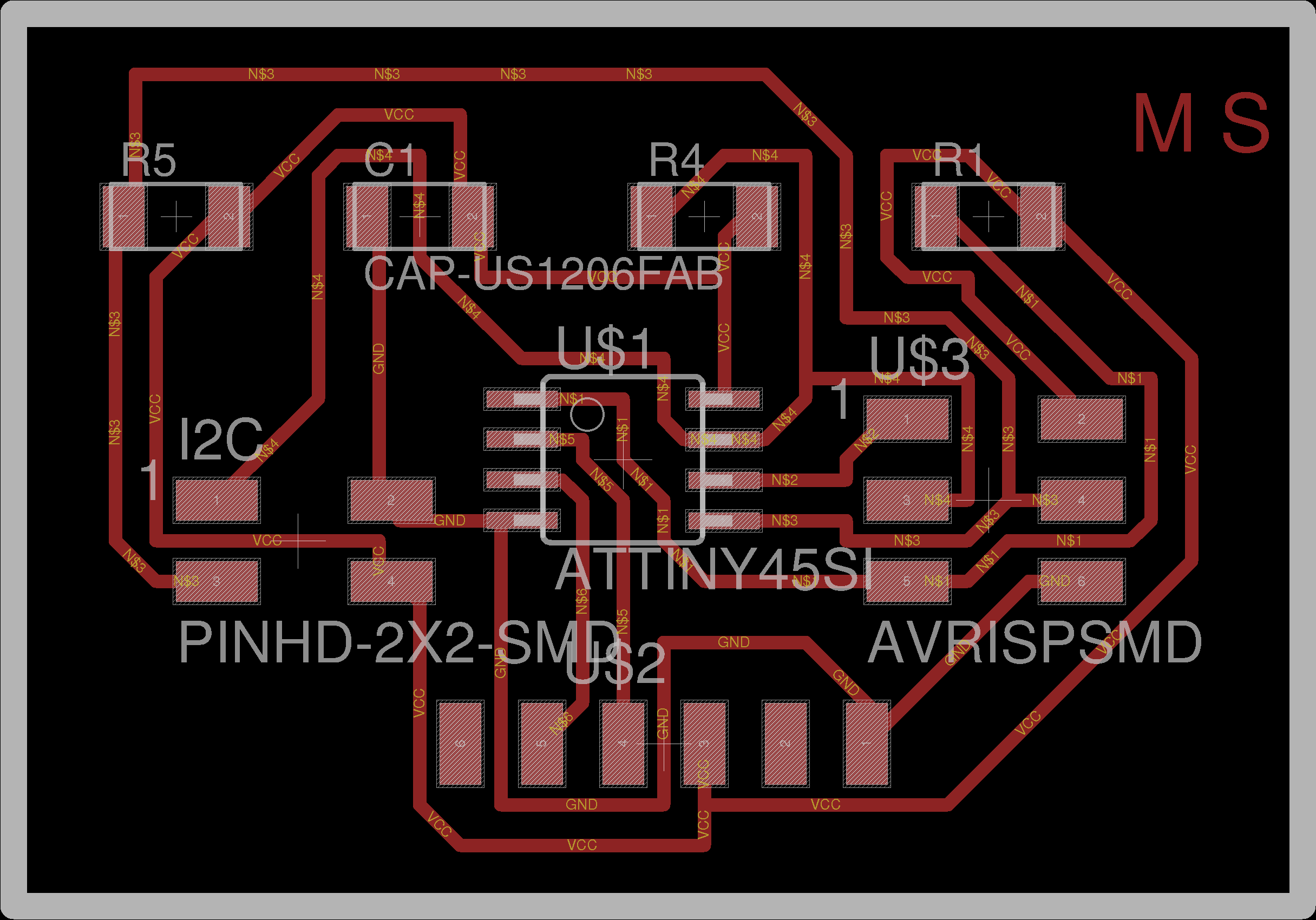
The mill traces,cut trace and final PCB design for master is given in the above figure
|

|
|
|---|
The mill traces,cut trace and PCB designed for slave is given in the above figure
The procedure used for milling is same as before ,which has been already described in electronic production week.

The pcb obtained after milling in modela,from the figure it is evident that there is a small short circuit happened in slave which I carefully elliminated using knife.
Components used by master include
|
Components used by slave include
|
|---|

the final pcb obtained after soldering
Embedded Networking
In Embedded system we have two efficient types of networks
- BUS network
- Ethernet network
The BUS connects network devices and is used to transfer large amount of data.Some of the protocols used include SPI,I2C and CAN .Here SPI means serial peripheral interface,I2C refers to Inter–Integrated Circuit Communication Protocol and finally CAN means Controller Area Network .On the other hand Ethernet network uses TCP/IP protocol .
Inter–Integrated Circuit
For my networking week I have planned of implementing I2C protocol with two attiny44 board and also intrested to extent it with attiny45 board which was made in the previous week. Lets have a breif idea about the I2C protocol.
I2C protocol was Developed and patented by Philips for connecting low speed peripherals to a motherboard, embedded system or cell phone.Some of the prominent features of I2C includes
- Multi-master, two wire bus , up to 100 kbits/sec
- One Serial data line (SDA)
- One Serial clock line (SCL)
- Master provides clock
- slave has unique 7-bit address for communication

I2C bus needs only two lines a serial data line (SDA) and a serial clock line (SCL) for communication. The data from one device goes to another through the SDA line, whereas synchronization clock for communication is provided by the SCL line. A Master can only initiate a data transfer and Slaves will respond to the Master.We can have multiple masters on a common bus,but at a time only one will be mastering the bus. The SCL clock line will be always provided by the master. Slaves cannot initiate a data transfer in I2C communication ,it can can transfer data over the I2C bus, and slave will be always controlled by the Master.In I2C communication the mode of communication is byte oriented ie msb will be first transmited.Start of the communication is intiated by making SDA low while SCL is high.After the start Master sends address of slave (7-bits) on next 7 clocks followed by read/write request bit by the master ie 0-write to slave and 1-read from slave finally Slave ACKs by pulling SDA low on next clock cycle

For more details about I2C communication click here
Impementation of I2C protocol with one master and two slaves
I am planning to have a communication between three microcontroller boards.It include 2 boards od Attiny 45 made in this week and one Attiny 44 board made in week 6. Here the master is the attiny45 master itself and the other two are slaves.Fortunately FTDI pin out are available for the Attiny44 board.

I am using arduino programming for implementing I2C protocol.Here in the program it is visible that the master code contains two address 0x3 and 0x4 which is used to adderss the slaves connected to this master.The program is written in such a way that 0x4 is address used for Atitiny45 and 0x3 is address used for Atitiny 44.There are two variables x and x1 which are incremented continuesly ,the data send through the SDA line is actually the reminder obtained when x or x1 is divided by two,ie the data send through the I2C bus is either one or zero,which depends on the reminder obtained.

The program for the Attiny 45 slave is given below,from the code it is clear that the address of the board is 0x4.So we can change the address of the node by editing the program. In the code it is clear that when zero is received as data through the bus the led will be switched on by the microcontroller and when data is one it will turn off the led.

The program for the Attiny 44 slave is given below,from the code it is clear that the address of the board is 0x3.So we can change the address of the node by editing the program. In the code it is clear that when one is received as data through the bus the led will be switched on by the microcontroller and when data is zero it will turn off the led.Therefore it will be operating in an opposite manner compared to the previous one

As discussed in the program the connections are made ie all the SDA lines are connected to each other and all the SCL line are also connected together.The master will be providing the clock signal and it is the device which intiates the communication

But when the connections are made and circuit powered ,the communication was extablished but the Atitiny 45 slave was not responding .I checked through the connections,there was now problems.I spend more than a day for sorting out the problem ,but I was not able to rectify.The working of my circuit is given below
Impementation of I2C protocol with one master and one slave
So I thought of using the Attiny45 as master and Attiny 44 board as slave,ie only one ,master and one slave.I edited the program for single slave.In this program 0x4 is given the address of the slave ,it can be clearly noticed from the programs given below. The program below is for the master,it send one and zero periodically to the bus,addressing a single slave.

The program below represents the slave program,the address of the slave is made 0x4 in the program.The slave will on the led when data in the bus is one and off the led when data is zero.

Finally ,as expected and got previously it worked .I used DSO for checking the signals .

Finally this I was able to implement I2C communication between one master and one slave.The vedio given below shows the output clearly
Download my programs from here .