
WEEK 15 – NETWORKING AND COMMUNICATIONS
Weekly assignment:
This week's assignment was to build a network connecting at least two processors
Some theory...
To get started to this topic, wich was new to me, I've taken a look at the related chapters on the book Make: AVR Programming
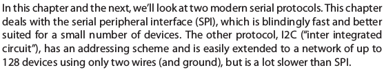
Here I've learned that there are two main wired interface protocol SPI (serial peripheral interface) and I2C (inter integrated circuit)
The main difference between them is in speed and number of devices connectable
I decided to try I2C connecting two boards with ATtiny44 I made during previous weeks
This protocol works with a master and, at least, a slave. The master "asks" something to the slave and the slave "answer" something else
As I learned, I2C is defined as a synchronous protocol, since the master controls communication by sending timing signals
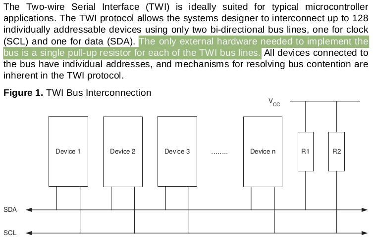
It uses two wires: Serial Clock (SCL), for the timing indeed, and Serial Data (SDA)
In a typical I2C conversation the starting signal is a low SDA, then the master starts the clock with a low pulse
Data are setup when the clock is low (the master is going to write) and read when the clock is high (the master expects to read). This defines the write and read direction
For the communication itself each device has 7 bit address, but after any message another bit is sent by the receiver to say that the message have been received
When this bit has a low value (0) is called ACK (acknowledge) and means that the signal is ok and the sender can continue to send, when it's high (1) is called NACK (not acknowledge) and the trasmission is going to end for some reason
Building the network
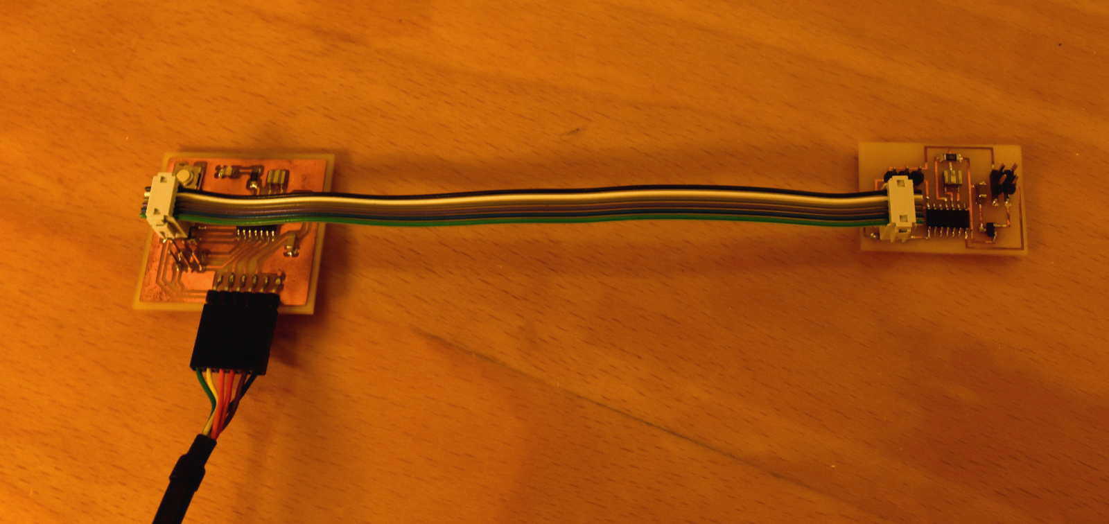
Once I've focused those basic things I tried to make a connection
As I already said I used two boards with an ATtiny44 and the Arduino IDE as the programming environment
Note: since I completed the interface assignment (week16) before this one, you can find my first approach with Arduino IDE there
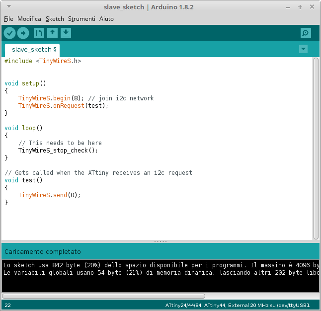
In any case I had to manage other new things for this assignmant, first of all TinyWireM and TinyWireS libraries, those both are modifications of the original Wire Library (which allow to communicate through I2C) to use it with an ATtiny processor
So after I've read some documentation about how to specifically code
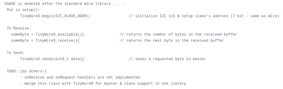
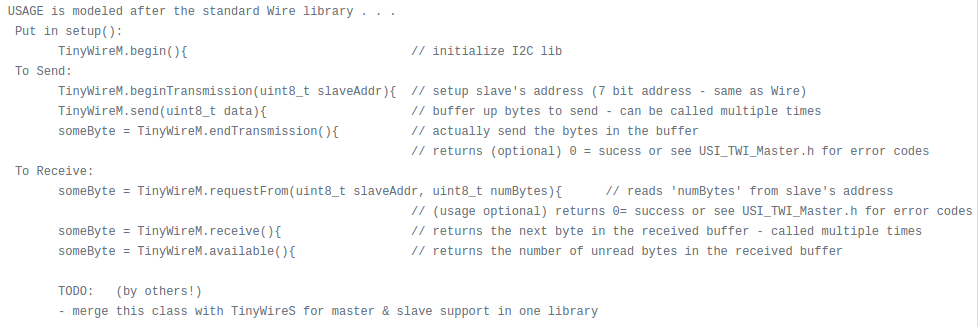
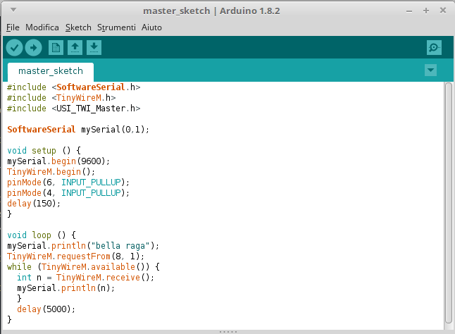
I moved to write some code for both the master and the slave (the board connected to the FTDI cable is the master)
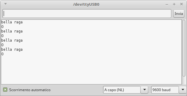
But at a first moment nothing appeared on the serial monitor, in wich I was finding my feedback to see if the code was working well
After a bit of debugging I realized that on my board there weren't pullup resistors... and as explaned in the picture above and also in the library instructions they are very important
To fix this problem I've inserted internal pullup in the code
And finally it worked
In conclusion I want to say that it was very interesting to make two boards communicating. Even if for this first time I didn't anythig of particularly complex, it was a goos starting point to me for future attempts and experimentations
You can find my original sketches for master and slave here