
FINAL PROJECT
Concept
For the final project task I decided to make a machine for storing and distributing components or small tools
I named it Vending Carousel because it is a vending machine, but it looks and behave like a carousel
I decided to make it with this shape because it let me to reduce the number of degrees of freedom and so the devices and actuators employed at the lowest amount is possible
In addition I wanted to make it as small and functional as possible, since I imagined it could be placed on a workbench or a shelf in order to be easily accessible
Given that it would be visible, I tried to make it as pleasing as I could
Design
Once I defined the main concept I started to bump against the concrete making issue, as motion, dimension, stability, and other things like that
So I started drowing some sketches by hand just to have some reference and thent I moved to 3D modeling (this is the part I like the most)
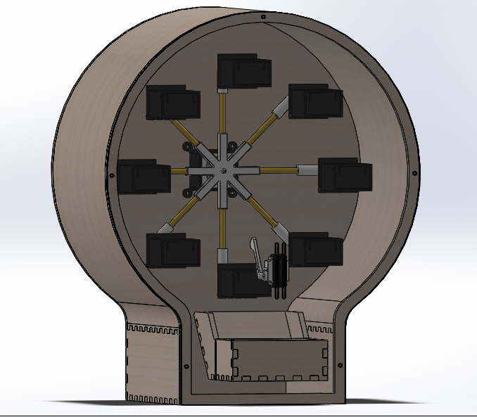
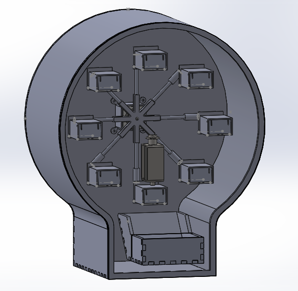
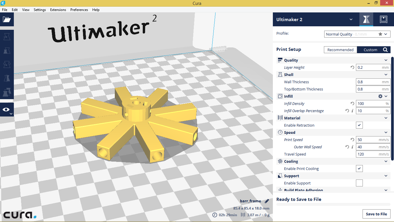
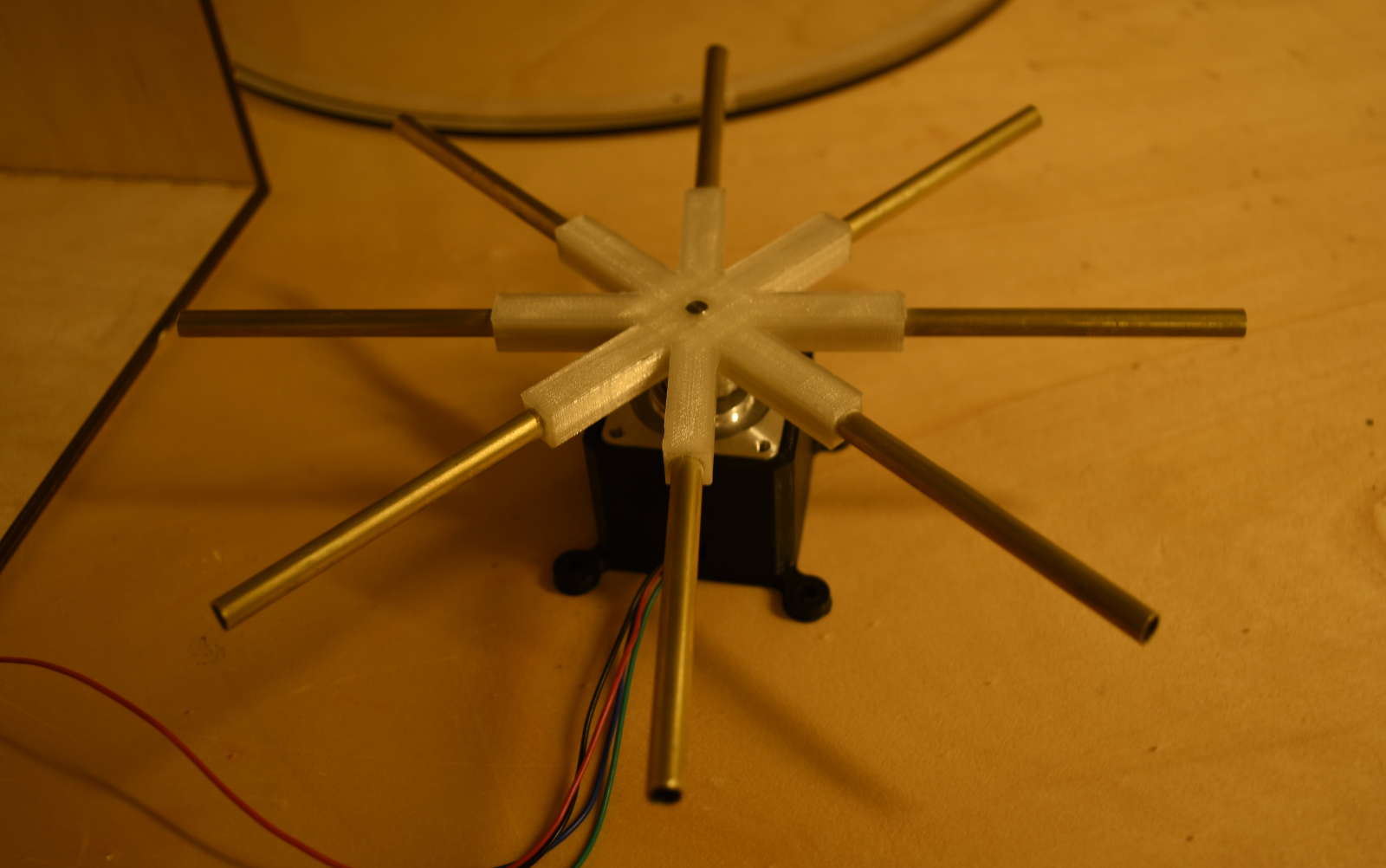
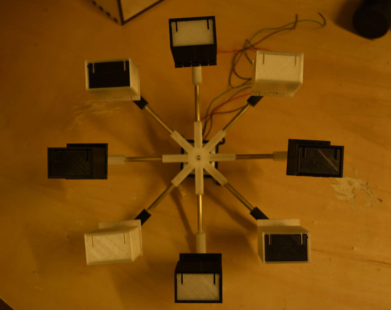
I began modeling the main frame (the one which makes the rotatory movement). I decided to set height boxes and so just as many spokes
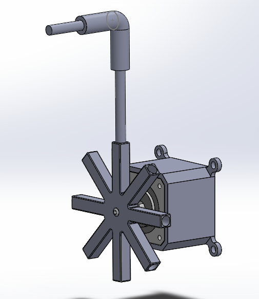
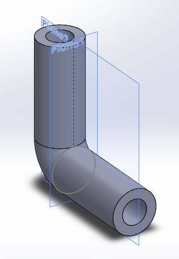
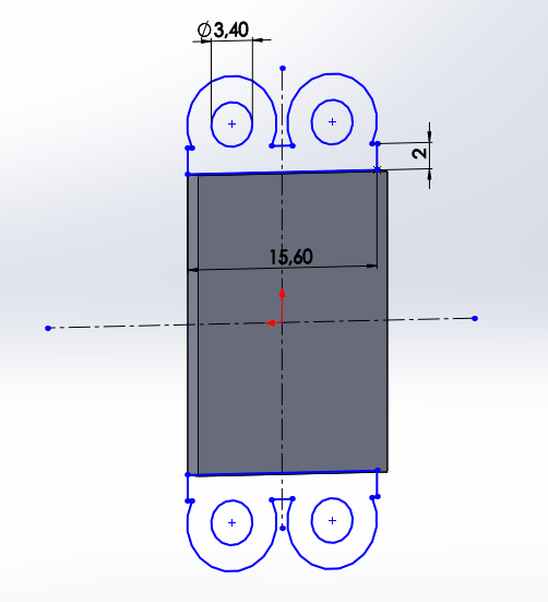
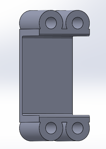
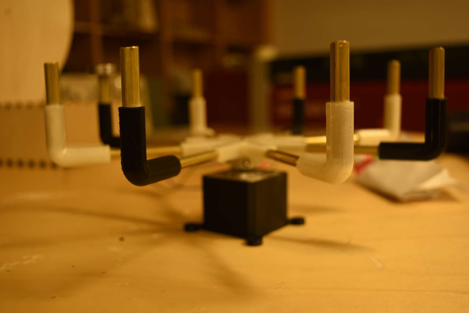
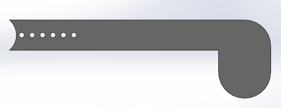
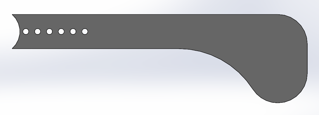
To bend the rods I designed those joints
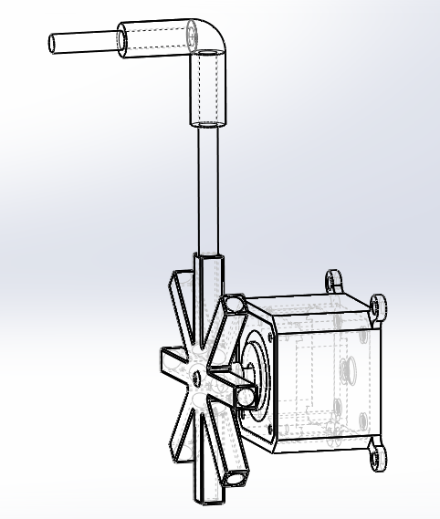
As is visible in the picture, the motion is given by a stepper motor and the main frame is directly joined at the motor shaft and fixed with bolts and nuts
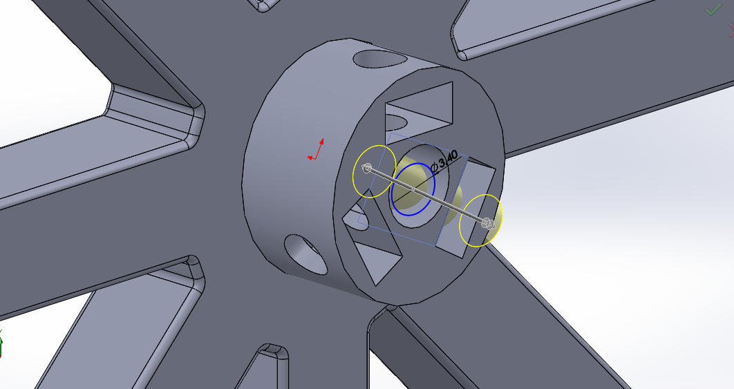
The rectangular fissures in the picture are the nuts slots
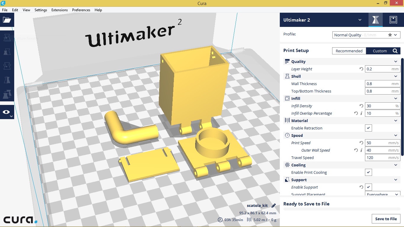
Once the frame and the motion were managed, now was the time to think at how realize the boxes. And it have taken a bit of time to think at...
About boxes I had several problems to solve, such as how to make them leaning (and then back in horizontal position), how let the contents come out from them, how let them stay in the same position not turning upside down
I managed all those issue with a specific design
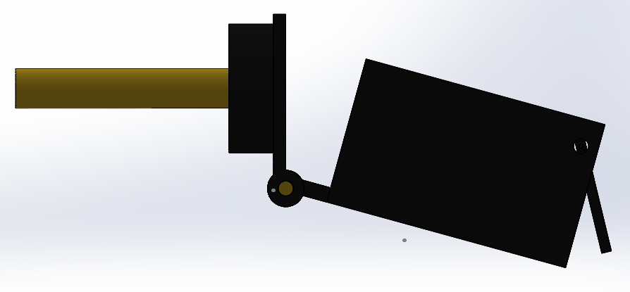
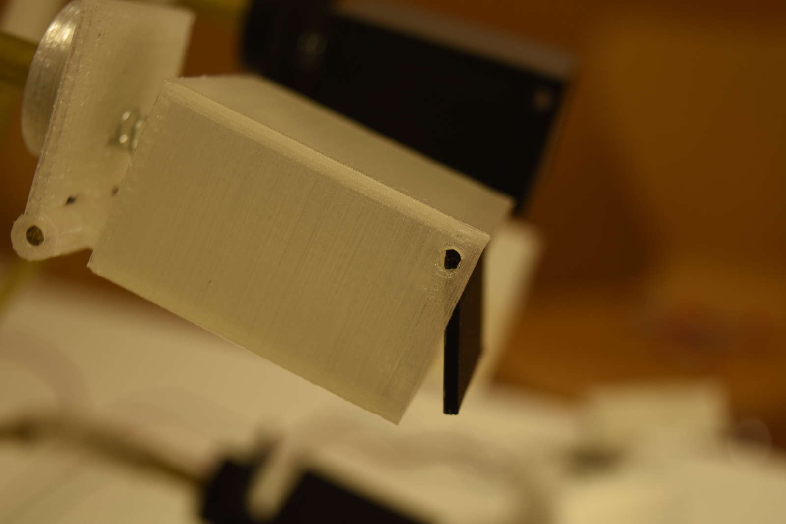
Boxes are made up of two complementary pieces joined together by a metal bar
Hinge Box by allarollonz on Sketchfab
This system let the box container part lean forward, and a spring connecting it to the other make it come back when the force is brought back
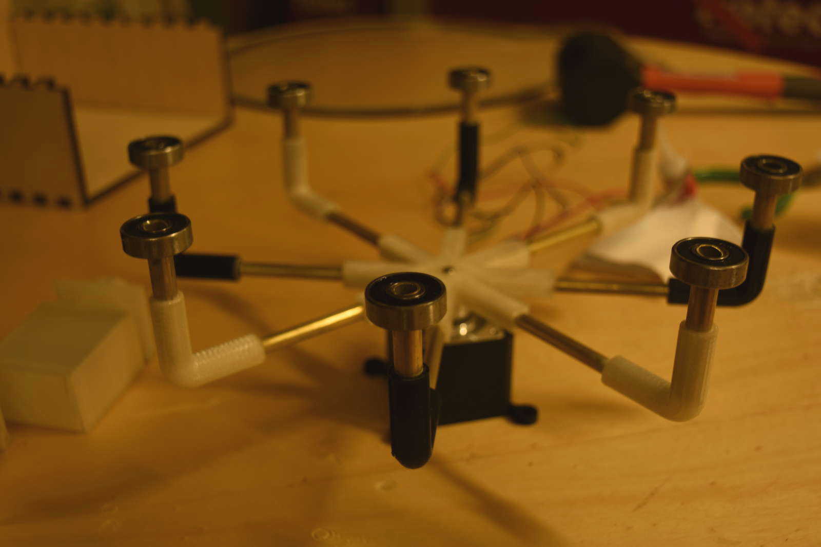
A ball bearing connecting the box and the rod make it to stay in the same orientation even when the frame is rotating
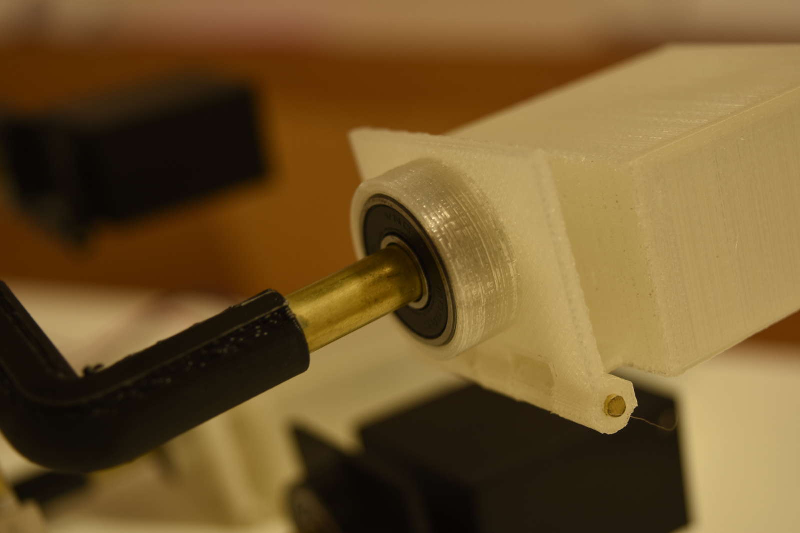
And a swinging shutter lets the contents come out due to the gravity force
Now another question had to be answered: what king of machanisma, or device, or actuator should I employ?
At a first moment I thought at a solenoid. So I browsed the internet to see which size and motive power solenoids were available
I was looking for something as small as possible, but when I went to try a small kind we had in the lab, I've been aware that it had not enough power for my requirement. So I thought to use a bigger version
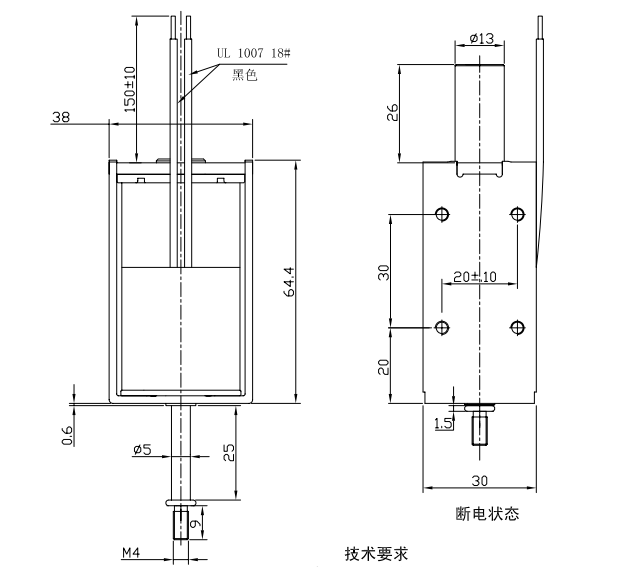
Then I included it in the machine 3D model
I modeled it by myself measuring the real one with the caliper
Solenoid by allarollonz on Sketchfab
But when I moved to test it I've found that the motion of the rod was too short, and It couldn't incline the box enough to release content
So I started to think at an another option...
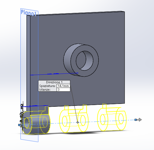
The servomotor was the answer. Emploing a servo I could even decide the inclination angle. It would have been perfect for me!
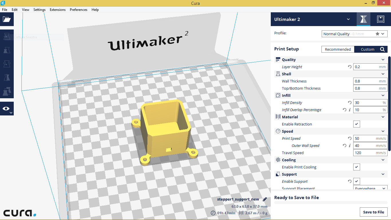
I've choosen my model among those we already had in the lab (we have several kind) and I've modeled it to include it in my 3D assembly
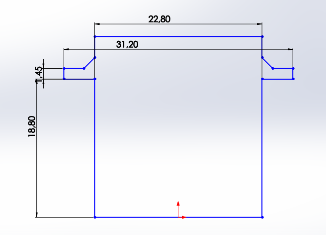
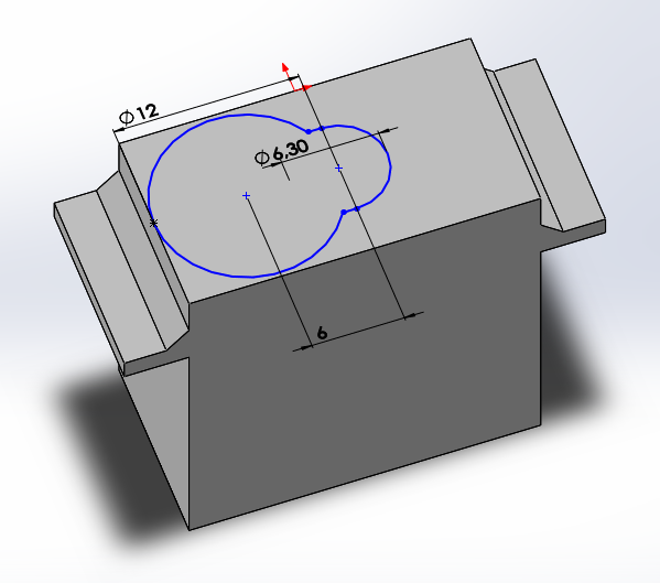
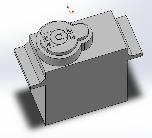
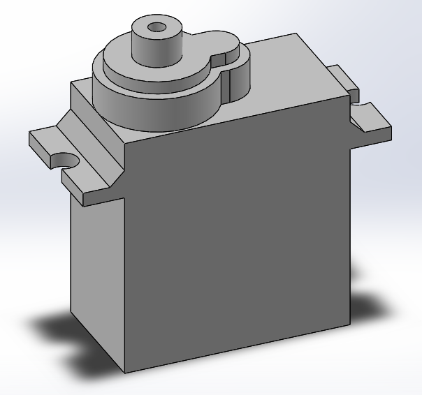
I've also designed and modeled a support
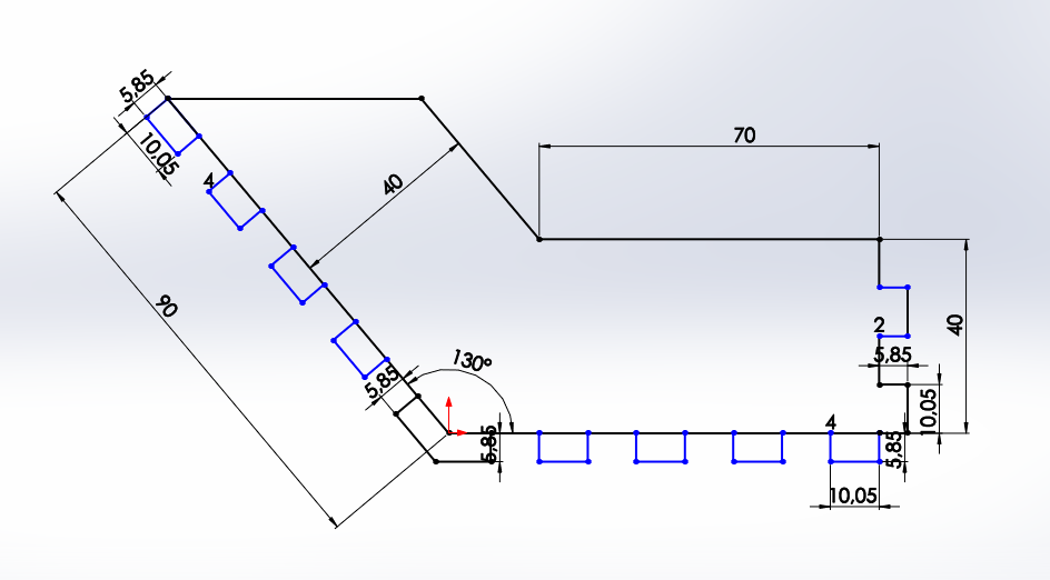
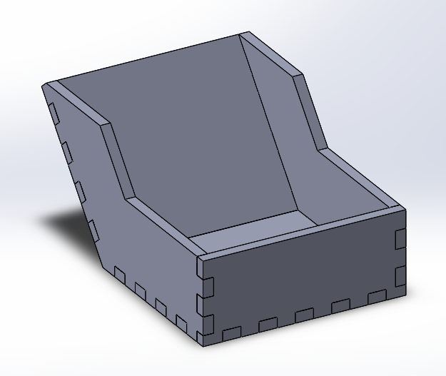
Moreover I designed the external machine case, and also the outer container, which collect the released contents
Machine Production and Building
Once I completely finished the design and made the Assembly in Solidworks, I was ready to produce my components
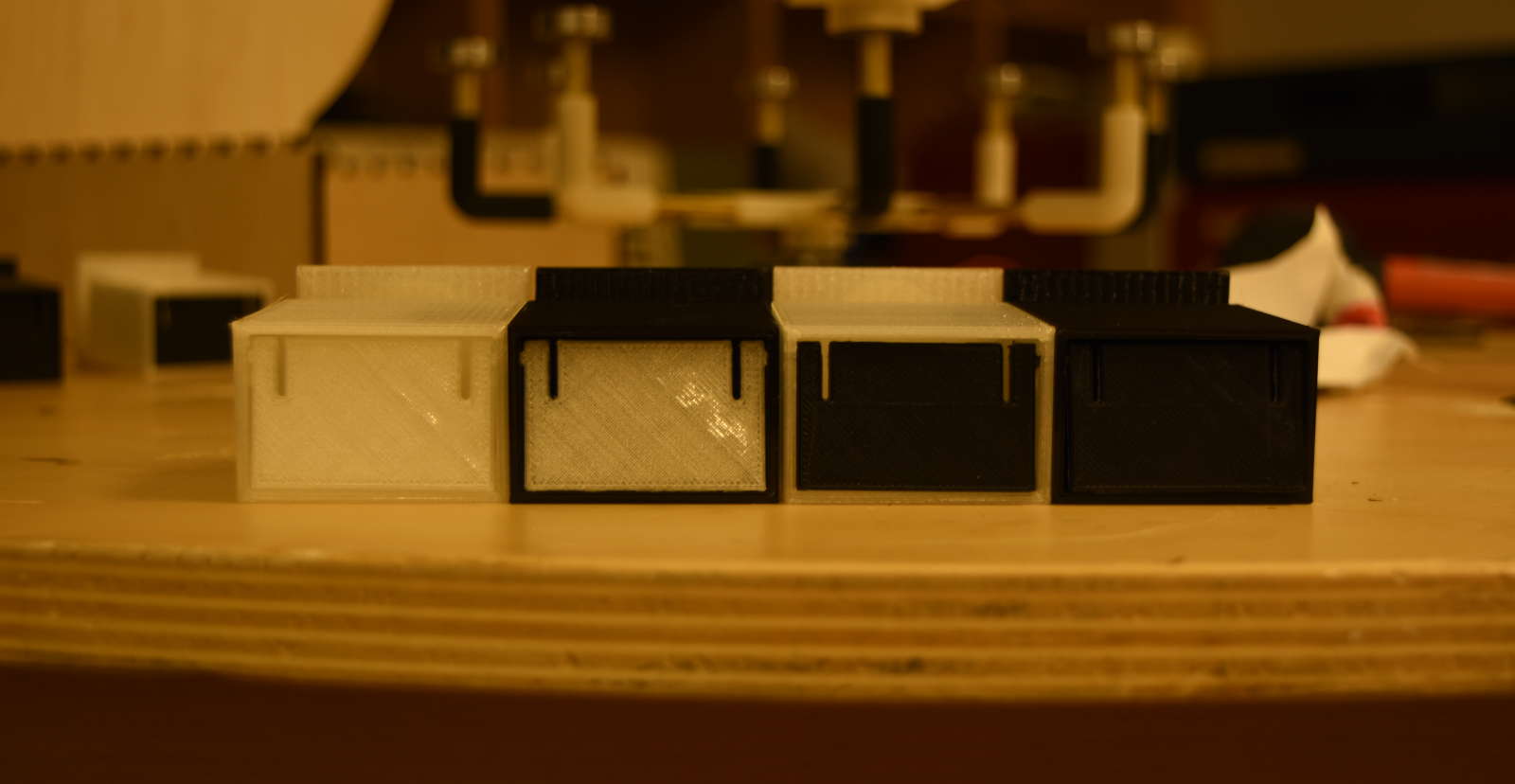
I 3D printed all the boxes kit, the crousel frame, the rod joints, the stepper motor support (to fix it to the machine case) and the servomotor frame
So I started assembling the carousel frame
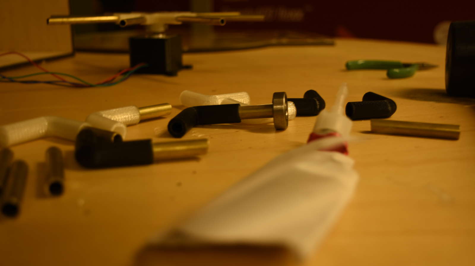
I used superglue to fix rods and joints together
After that I moved to the laser cutter to make the machine case
The most of the structure is made of birch plywood
Then I added a plexiglass panel fixed with screws, and so removable for manteinance or simply to refill the boxes
It also has two vertical fissures to hold the servo support that allow to adjust the servo position
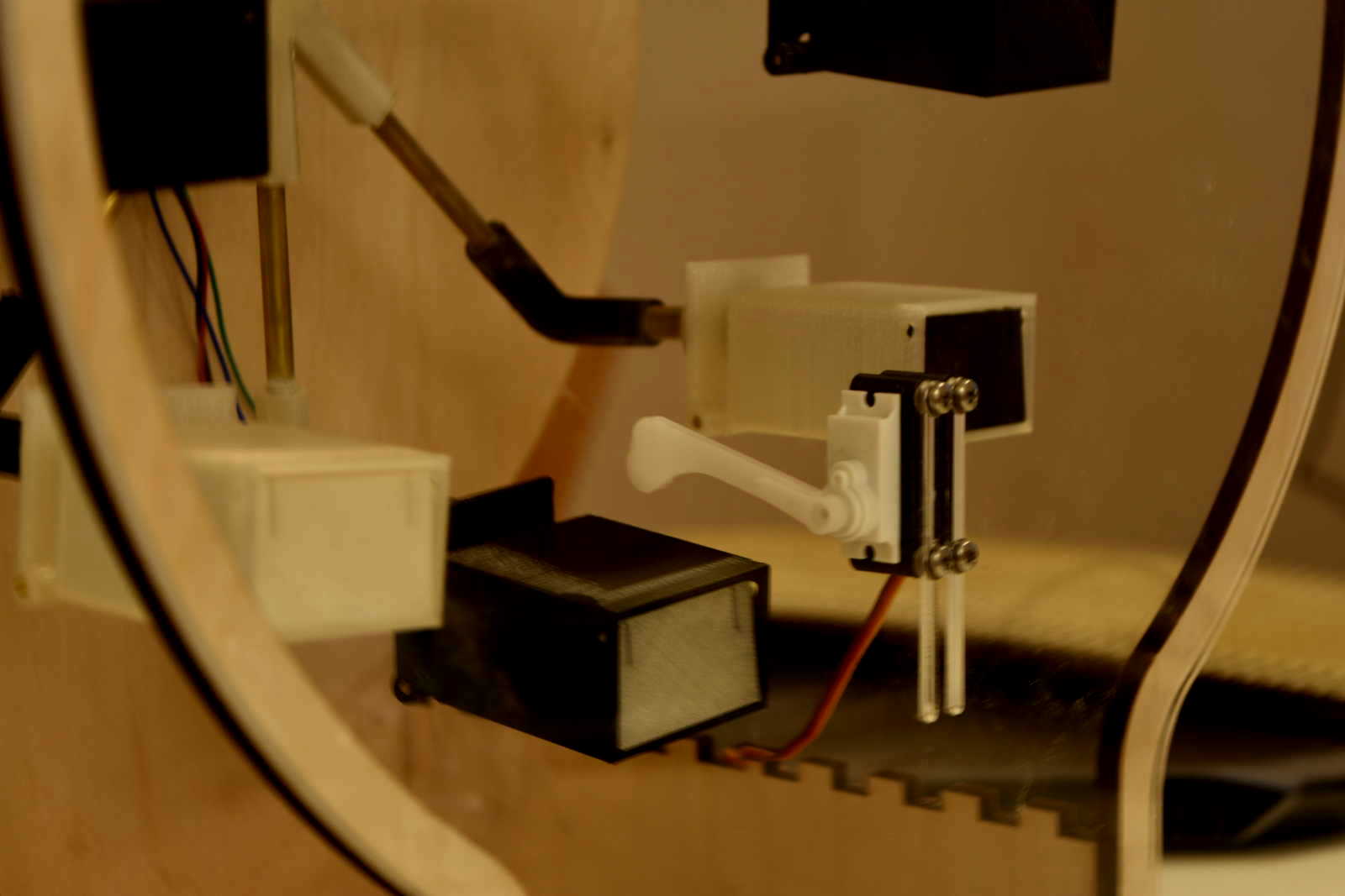
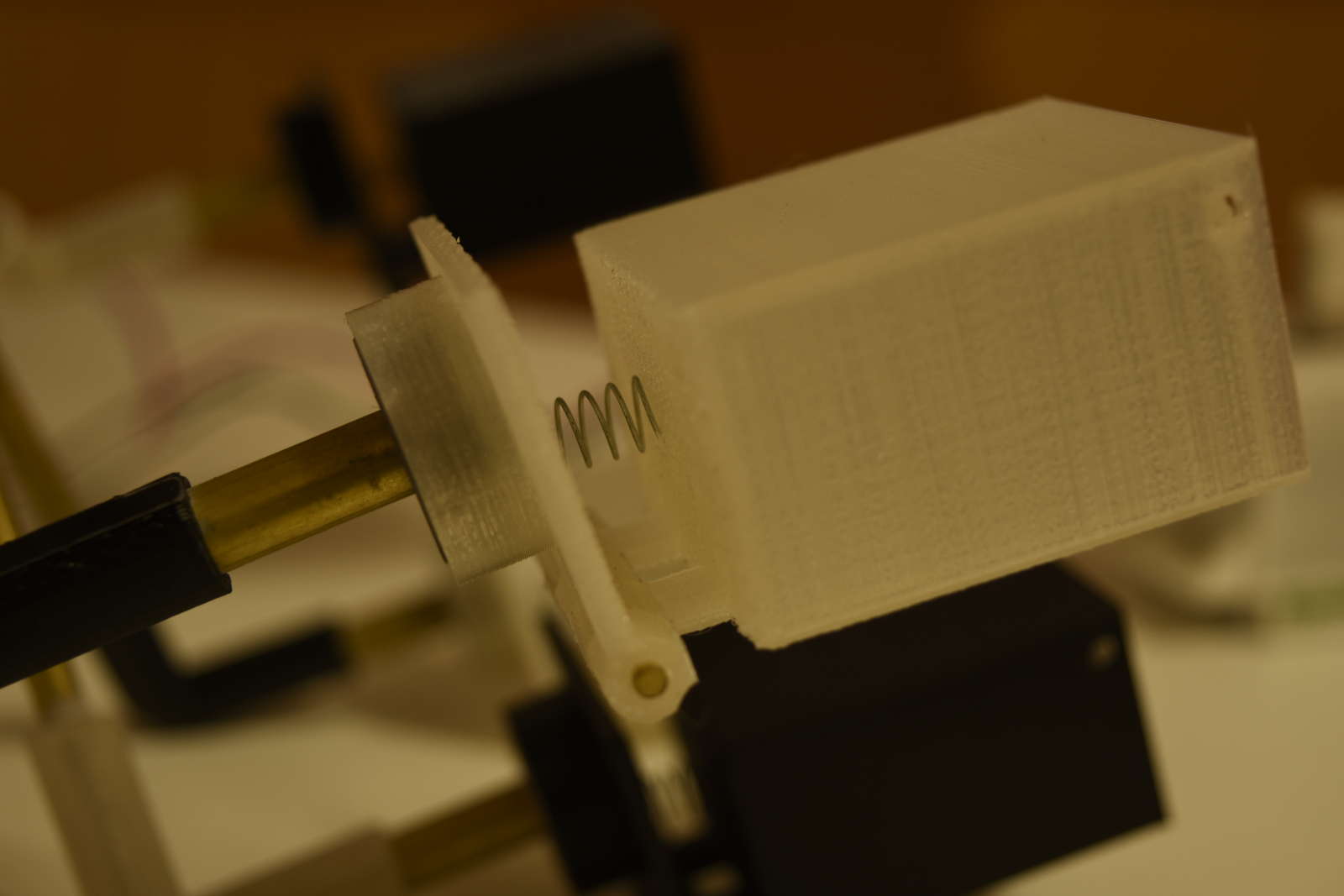
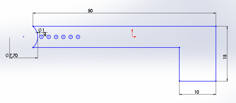
I added a lever to the servo because its original one was to short to cover the distance. I've mesured the servo lever with the calipers and designed a version which would fitted with the original one. So I laser cutted white plexiglass
Servo Motor by allarollonz on Sketchfab
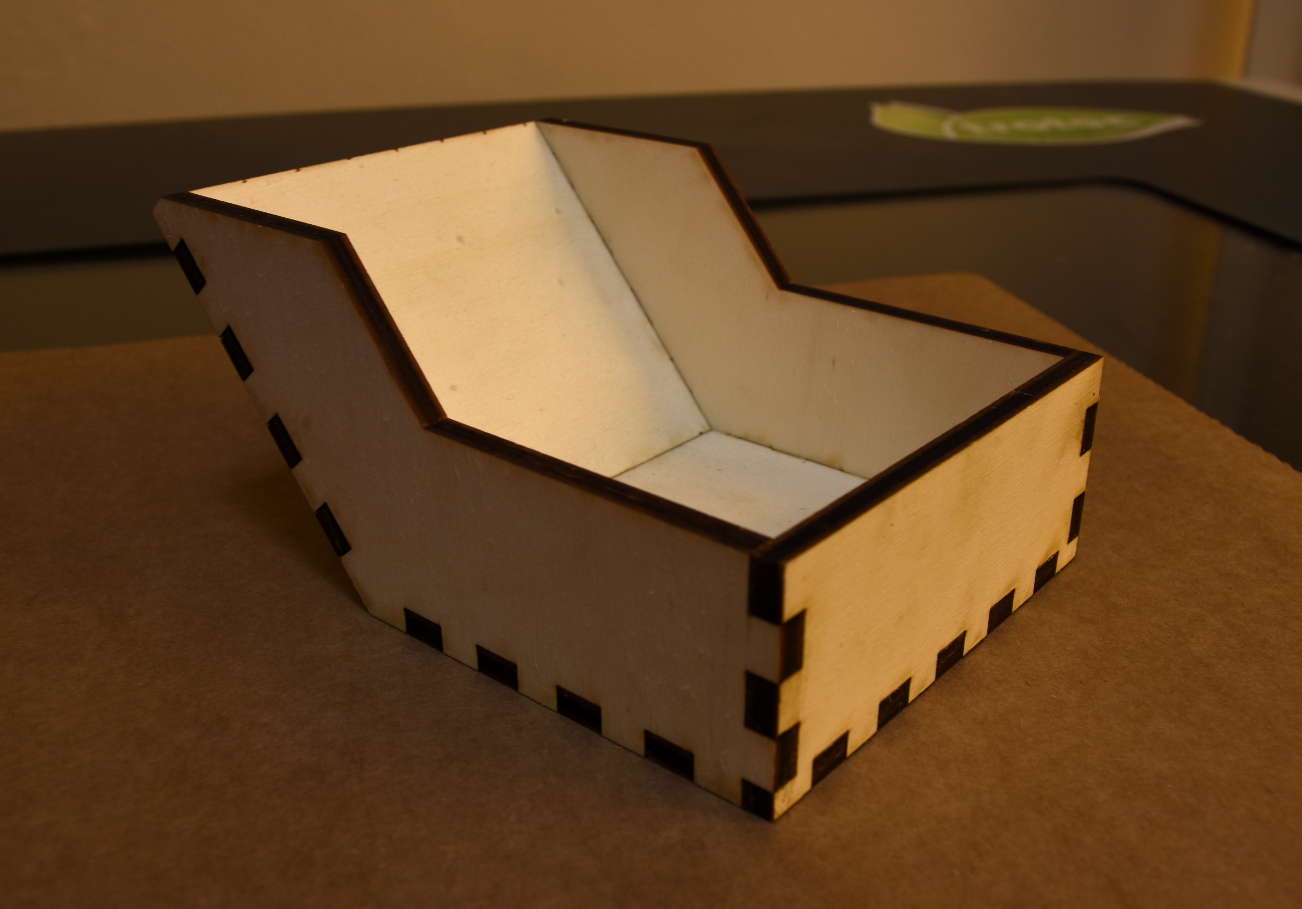
The container instead is made of poplar plywood
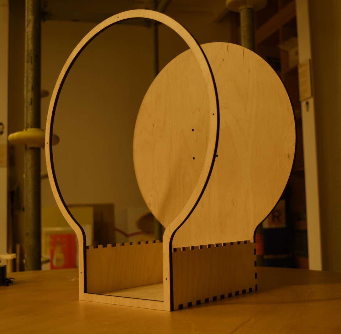
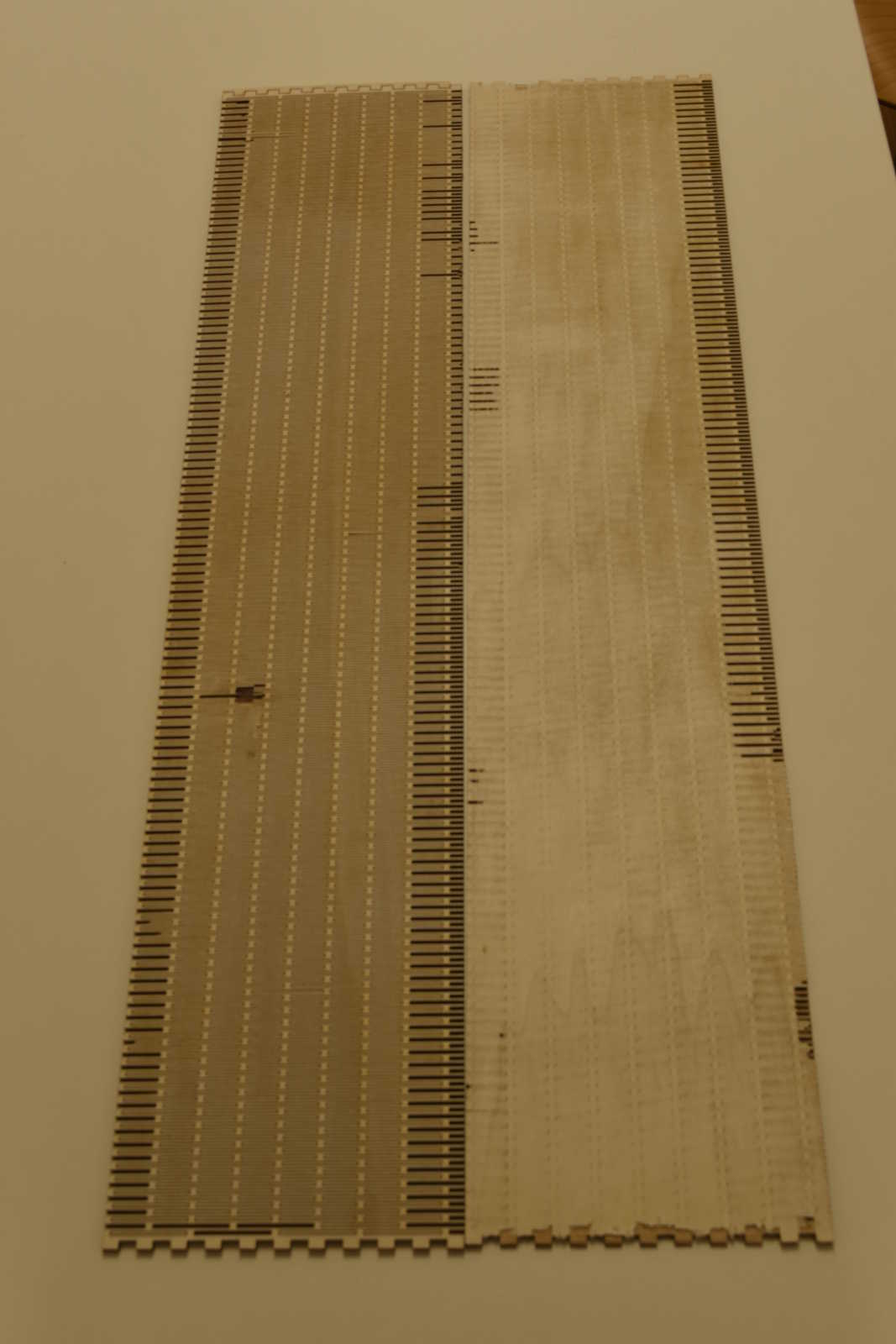
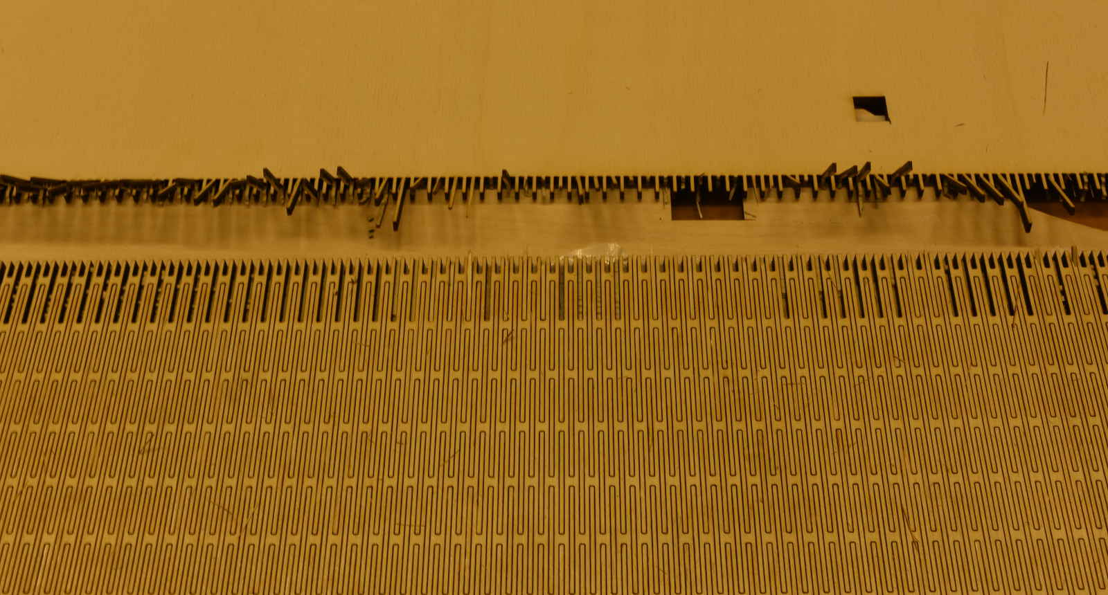
The last cut I made, since I was a little bit scared, was the lateral rounded side of the cover. I've been particularly creful in this case because the panel was long 100cm and had a lot of very thin living hinges (2mm)
To decide what kind to use I browsed on the internet and I've choosen the one you can see in the picture below

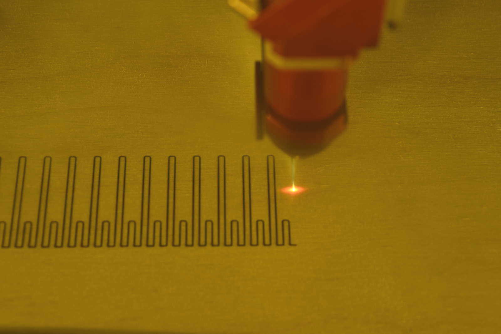
My fear was well founded, indeed in this phase I had the first of my main problems
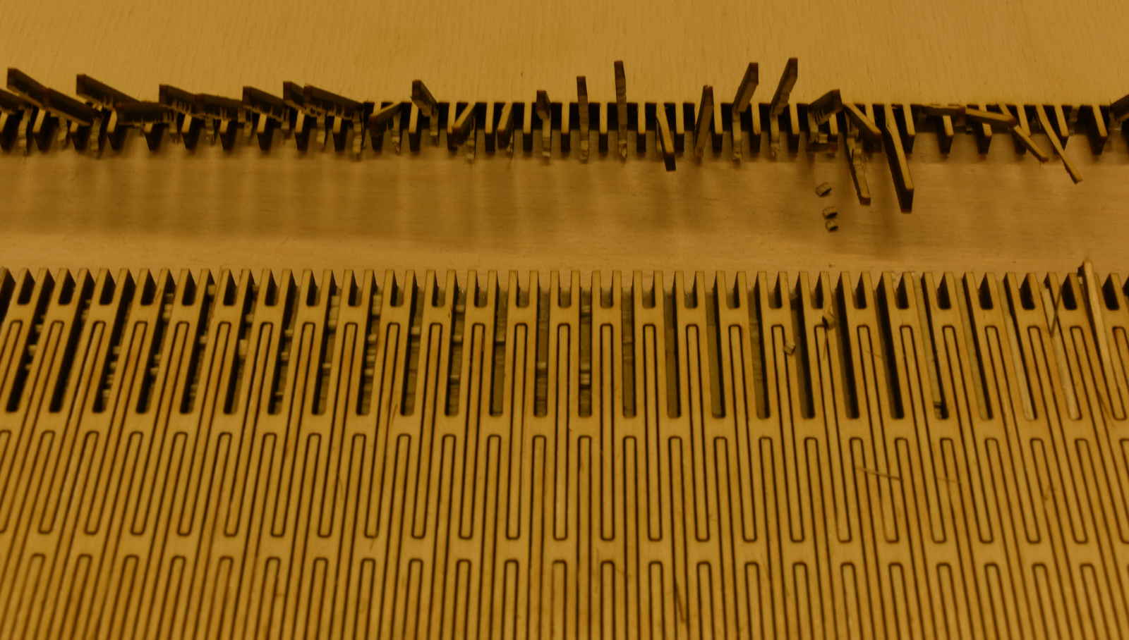
When I finally tried to cut it I've got this bad outcomes
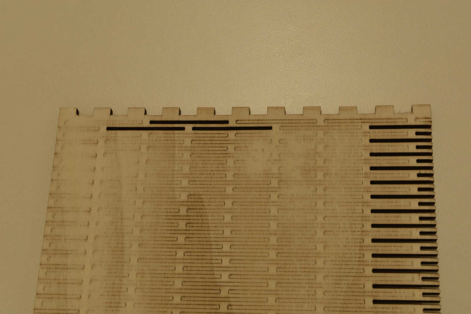
I tried once with birch and twice with poplar, and the outcome was everytime the same. The cut began well but at a certain point the laser stopped to cut the bottom of the board
Before to run the cutting I made lots of attempts with different settings, using small pieces, to don't waste too much material. And during those the cuts went well, so any time I tought I've found the right ones. But when I moved to cut the whole piece I gained the same outcome
I even cleaned the laser lens between one and other. Given that it was a lenghty cut, I tought that during so much time they could get dirty, but I had no significant variations
Since the only variable was the panel lenght I think that the problem was there. Indeed I've found that, since wood panels are never perfectly flat, the cutted portion (living hinges) bends even if I taped all the borders to fix them to the machine plate
Due to this the laser lose the focus and the cuts don't work well
In my next attempt I'm going to fix all the board to another support with double-sided tape, in this way even the cutted portion would stay fitted to the plate
Update: Living Hinges
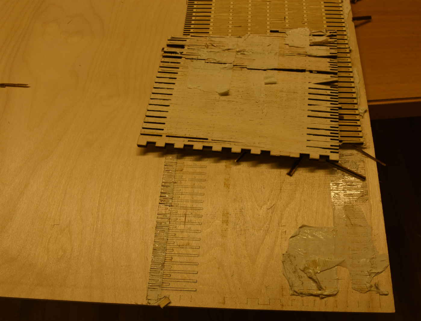
As I said I tried the procedure to attach the board I would have cut to another wasted board to avoid living hinges bending during the cut
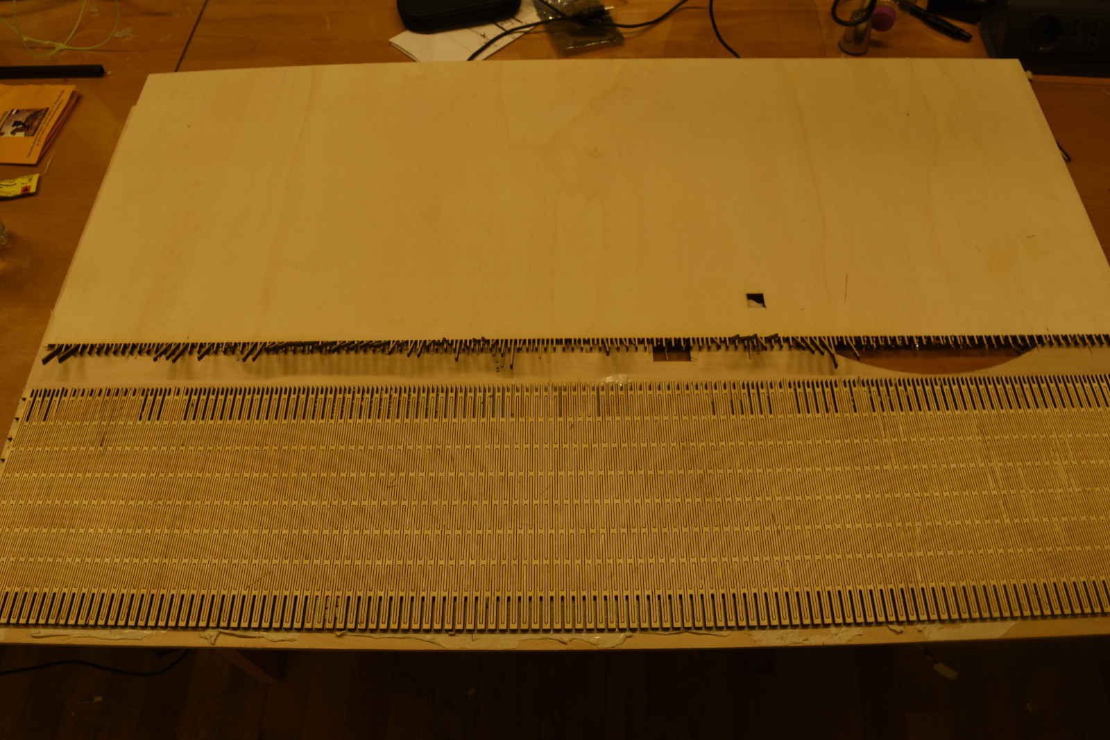
At the beginning It seemed It have worked
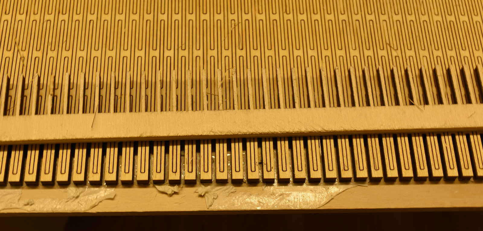
I've been able to remove the external pieces, being very careful to don't break anything
But when I moved to separate my cutted board from the support board, It wasn't easy at all, and after a long time of hard work the panel broke, because the tape was to heavy (it did its job even too well)
Finally in my opinion this procedure is not the best, otherwise you have to find the good balance in the double-sided tape. It should be heavy enough to fix the panel to the support board, but not too much to let you to remove the cutted panel
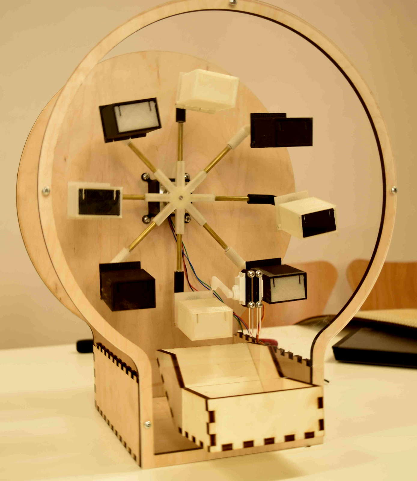
This is the assembled machine
Electronic Design and Production
My final project's electronic is quite simple, I only had to drive a stepper motor to make a rotatory motion of the main frame and a servomotor to incline boxes
To manage this I've designed a board controlled by an ATtiny44 which has enough pins for both the devices
BOM
ATtiny44 microcontroller
100uF 25V capacitor
20MHz resonator
10K resistor (2 pcs)
0 ohm resistor (2 pcs)
1uF capacitor
3x1 pin male (2 pcs)
8x1 pin male (2 pcs)
6x1 pin male
4x1 pin male
2x1 pin male
1 pin male
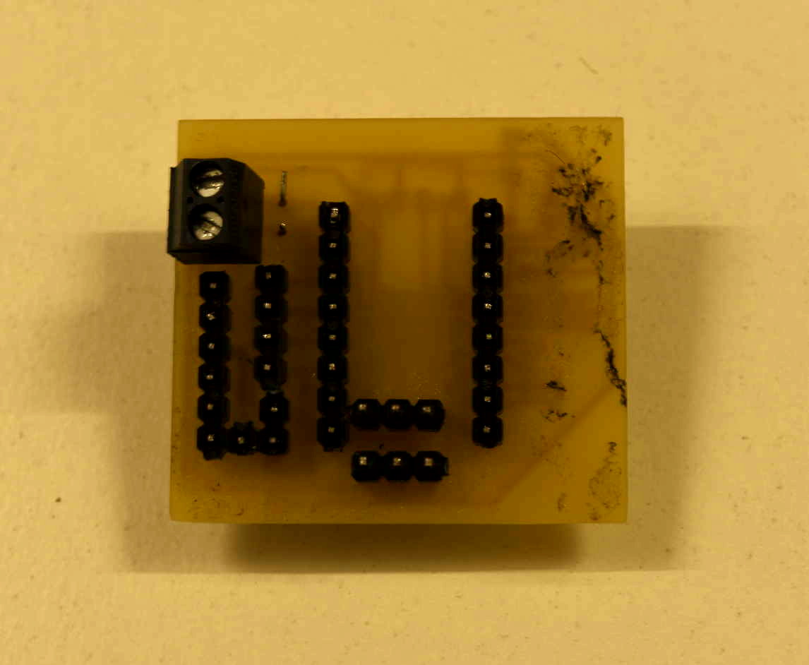
2 pin screw connector
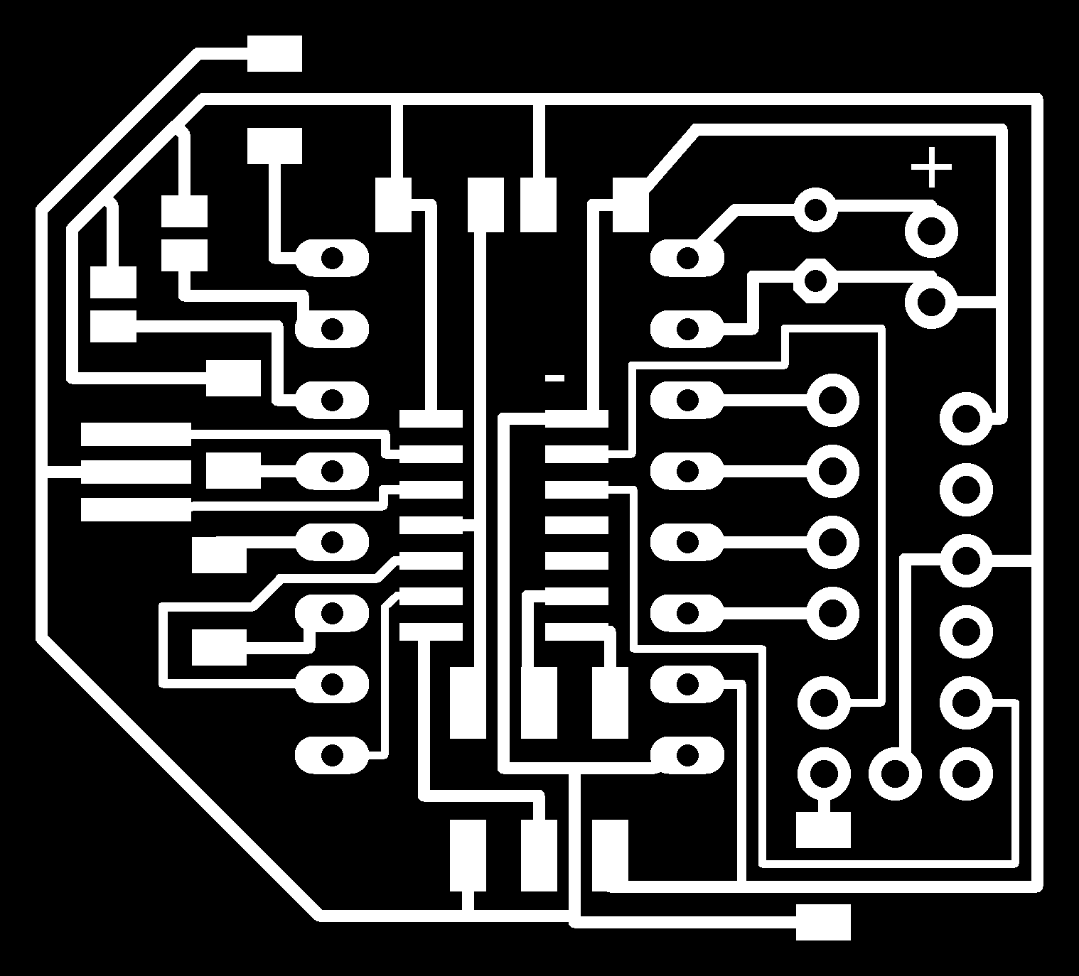
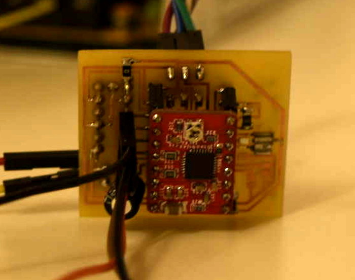
The stepper motor is driven through a Pololu A4988 stepper driver, and both are powered by an external power supply at 12V (in my specific case) but just for any circumstance I set an up to 25V 100uF capacitor

The microcontroller is programmed and powered trough a Fab ISP (bottom pins)
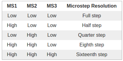
Since I was not sure if I would be going to use microsteps or not I laid traces but I didn't connected to anything for the moment
Programming
To move my machine I started writing a simply code just to move the upper central box until the release position, then run the servo to incline the box and turn it back in its original position
I wrote it as an example of the machine movement
To do this work I just used the stepper and servo libraries enbedded in the Arduino IDE
But I also wanted to try something more complex and refined
Then I wrote this code using the SoftwareSerial library
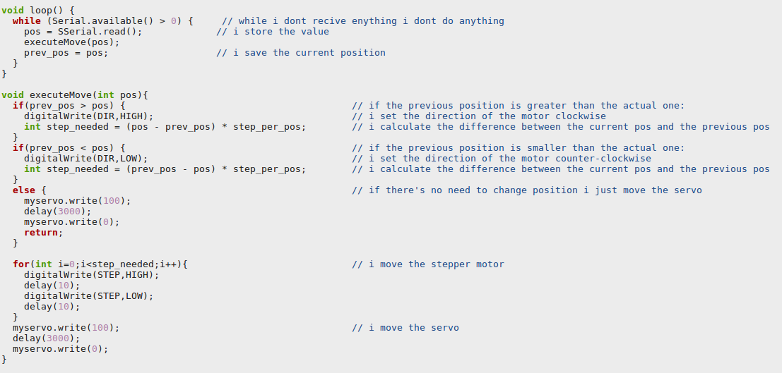
Thanks to my classmate Pietro which helped me with the mathematical operations among variables
As a future improvement I want to design a more refined board (with both TX and RX connected to the microcontroller to use properly this sketch and the same power supply for both the controller and the driver)
Downloads
You can find all the original files here otherwise here (GitHub)