My Final project

Idea for final project came from my photography hobby and one of its subcategory timelapse photography where photographs are taken interval timer with chosen gap. For example 5 second gap and then photographs combine to a video which normally contains 25 photographs (frames) per second. When you take photographs with 5 second gap you get 12 photos per minute so 25 photos take 2 minutes and 5 seconds then you convert photos to a video and get 1 second video. That way you get compressed video from a very long period of time and can make interesting effect like flower growing or landscape changing during different daytimes.
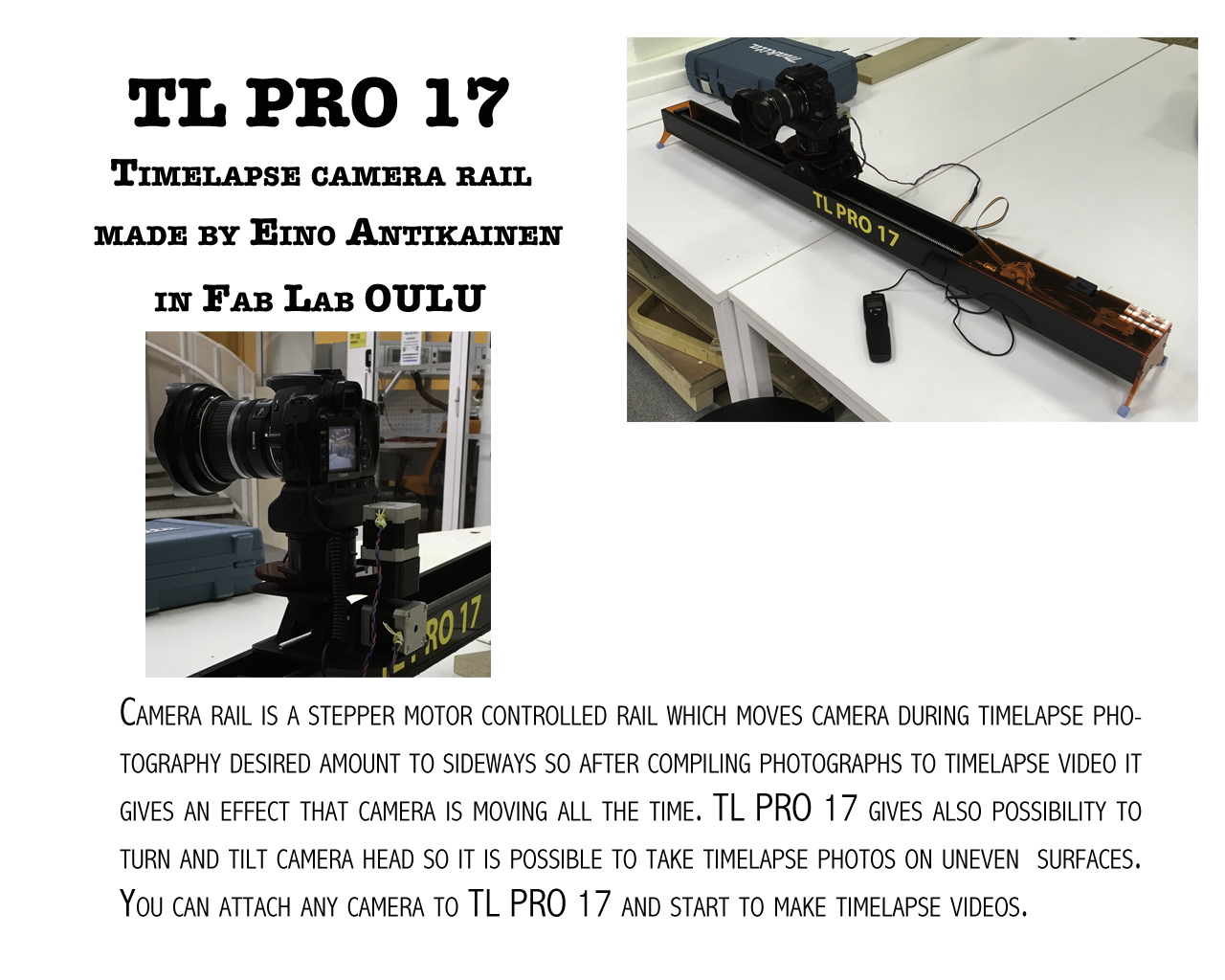
There is some similar products in camera stores but they are expensive and they have a lack of vital functions so I decided to plan, design and produce camera rail which suits to my needs and have all critical functions.
I went through next steps when I planned and produced my final project.
Last steps of my final project are explained in assigment 19.
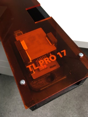
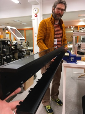
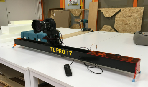
My final project is Camera rail (TL PRO 17)
FILES:
EAduino.sch, EAduino.brd, Eaduino traces.rml, Eaduino outlines.rml, Stepper board.sch, Stepper board.brd, Stepper board traces.rml, Stepper board holes.rml, Stepper board outline.rml, Part1.CATPart, Part2.CATPart, Part3.CATPart, Part4.CATPart, Part5.CATPart, Part6.CATPart, Part7.CATPart, Part8.CATPart, Part9.CATPart, Part10.CATPart, Part11.CATPart, Part12.CATPart, Part13.CATPart, Part14.CATPart, Part15.CATPart, Part 16.CATPart, Part1.stl, Part2.stl, Part3.stl, Part4.stl, Part5.stl, Part6.stl, Part7.stl, Part8.stl, Part9.stl, Part10.stl, Part11.stl, Part12.stl, Part13.stl,Part14.stl, Part15.stl, Part16.stl, Pcb rakki.CATPart, vetokelkka.CATPart, Pcbrakki.stl, vetokelkka.stl, Acryl leg.dxf, TL_PRO_17.hex, TL_PRO_17.ino, TLPRO17.apk
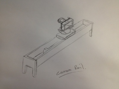
First sketch of Camera rail
Camera rail contains:
-
-body
-
-legs
-
-camera head
-
-camera mount (included camera head)
-
-camera tilt (included camera head)
-
-camera turn plate (included camera head)
-
-railings for moving camera head
-
-electronics
-
-electronics protecting plate
-
-on/off switch
-
-rubber plugs for legs
PLANNING
DESIGNING
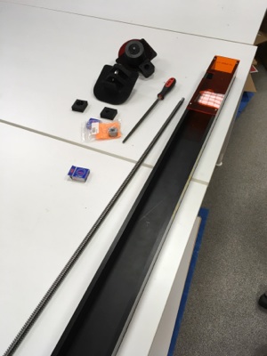
I decided that suitable length of camera movement is about 1 meter other dimensions are less important at this point and available components will determinate partly final dimensions.
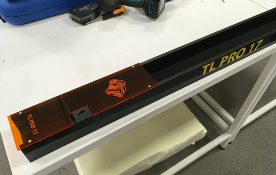
Naming camera rail to TL PRO 17. Idea came from timelapse photography what for camera rail is designed and I also add design and prodution year to end of name.
How to control the camera rail it is not decided yet but it could be computer, uploaded code or mobile phone app. There could be also possibility to move camera freely by using phone as a remote controller or presetting interval moves to camera. If using Mobile phone it will be connected to rail electronics with using bluetooth connection.
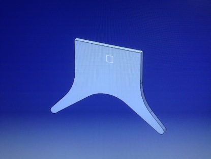
I start designing by sketching parts with CATIA 3D software based on my first pencil sketch of camera rail. I start from U shape body adding its both ends legs and then adding bearing units. I estimate need of space for electronics and lengthen body to 130 cm long. I also designed camera mount and mechanism which gives desired possibilities to move and turn camera. I also add step motors to CAD model as a place holder and helping for dimension designing. All camera mounting and mechanisms are designed for Canon 7D MK2 size camera body. At last I added some details like rubber plate to camera mount to give better friction and soften camera mounting, casted rubber plugs to legs for better friction, protecting plate against elements for electronics and additional closed on/off switch. All detail parts are designed to produced as a part of weekly assignments. I explain parts and assembly step in picture captions.
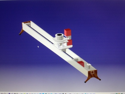
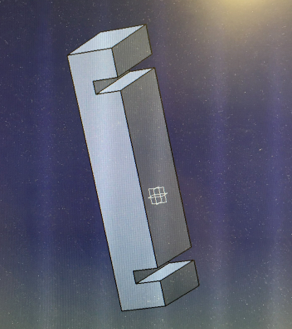
Overview of final Camera rail CAD model
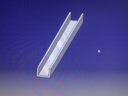
Camera rail body, assignment 7.
Bearing unit
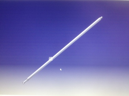
Threaded rod for helping dimensioning
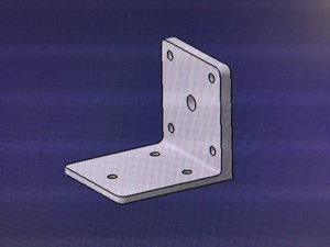
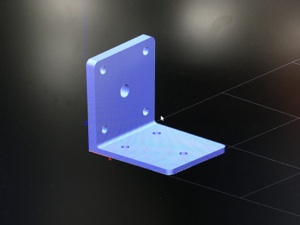
Legs for camera body, first idea is to make legs in assigment 14.
on/off switch, assignment 5.
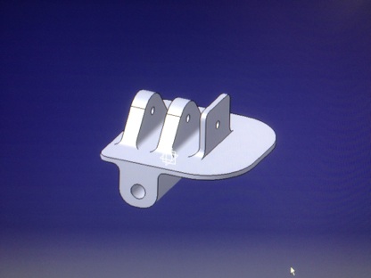
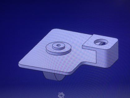
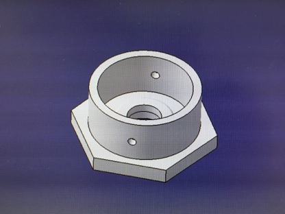
Camera head base plate
Tilt & turn plate
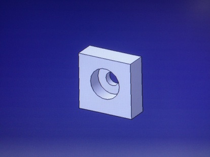
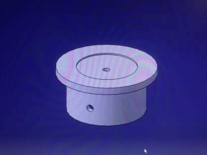
Turning base plate with camera mount base and pin holes
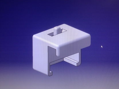
Camera mount with locking pin holes
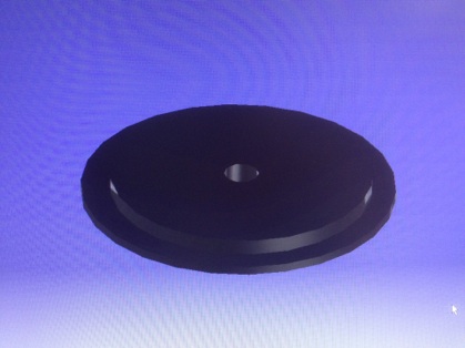
Rubber friction plate for camera mount
Rubber plug model to legs (casting), assignment 12.
MECHANICS
ELECTRONICS
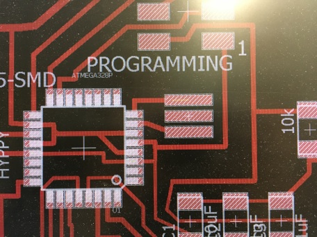
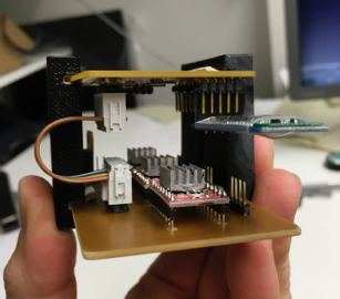
Electronics devided two parts Eaduino PCB card and Stepper motor control PCB card. EAduino is based on Arduino board using similar ATmega328 microcontroller. I have designed EAduino board to my camera rail use. Stepper motor card is a control board for stepper motors, power input and regulator from 12V to 5V for control currency. Designing of these card were challenging because it was hard to know which components should select. Also boards have lots of traces so pcb design was time consuming. During design there were multiple problems which all are with pcb design problems. Also I changed multiple component regulator to linear regulator at last meters of design. In Eagle was a bug that when I connected all wires which eagle adviced to connect to the pads in board view there was still one pad which is not connected. I found this out when I started to placing components. In schematic everything looks fine (even wire names) but even though there was no connection in board view. Erasing whole wire in schematic and drawing it again was a solution but final board I just add jumper by using soldering tin.
EAduino
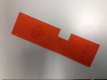
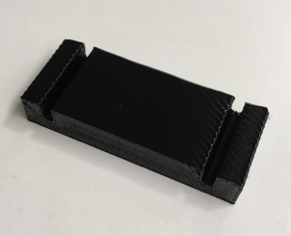
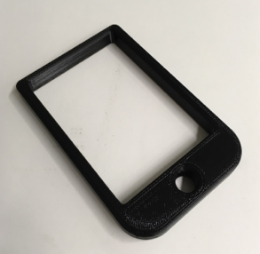
Earlier made electronics protecting plate, assignment 3.
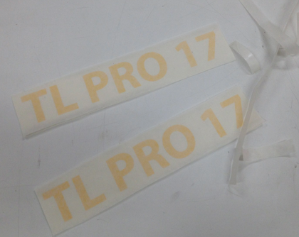
Stickers made by vinyl cutter, assignment 3.
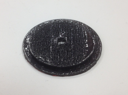
Printing rubber plate for camera mount
Rubber plate for camera mount, material Ninjaflex
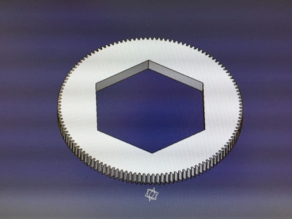
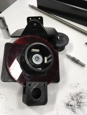
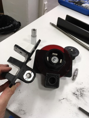
Camera mount gear
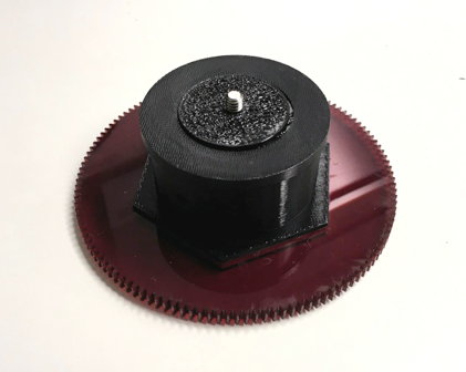
Camera mount assembly
CAD Models
Manufactured parts
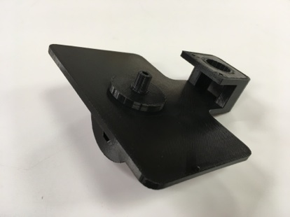
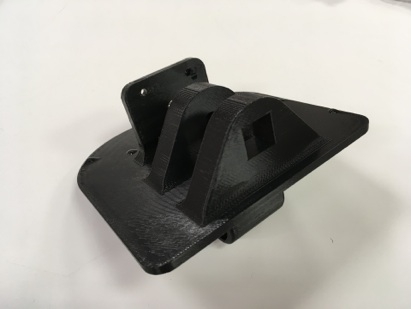
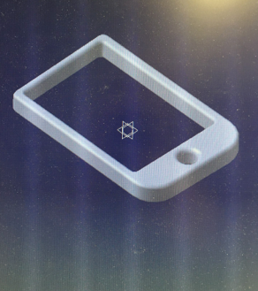
Printed camera head base plate
Printed tilt & turn plate
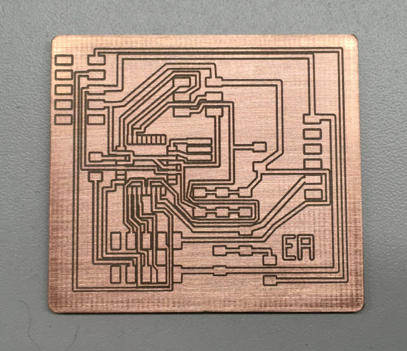
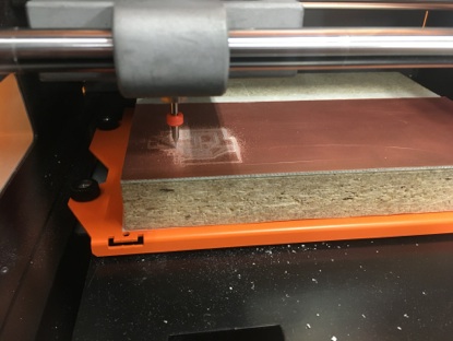
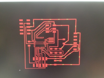
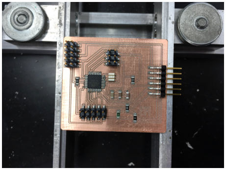
Milling EAduino board
Milled EAduino board
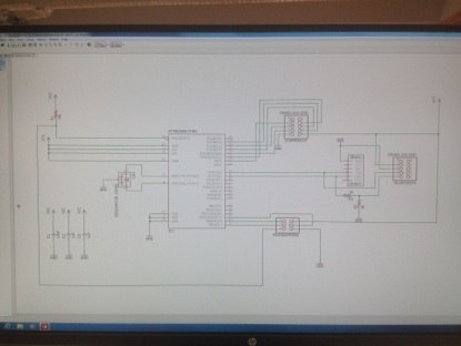
EAduino board schematic
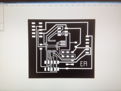
EAduino board in GIMP
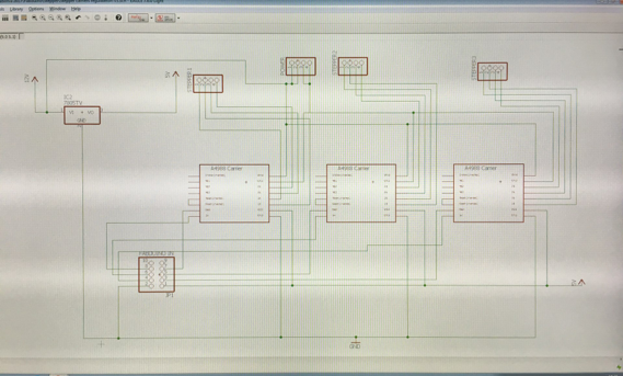
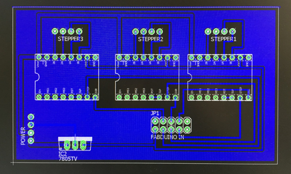
Stepper motor board schematic
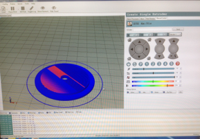
Motor holder in Catia
Motor holder in Insight
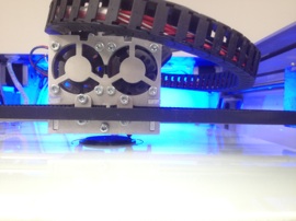
Printed motor holder
Bug in Eagle, resonator middle not connected.
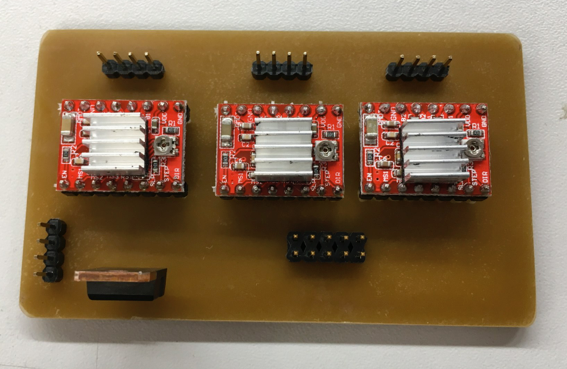
Components placed on stepper motor card
Stepper motor card after first reflow oven heating
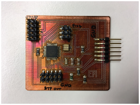
Final stepper motor card
Stepper motor board
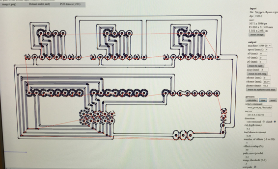
Stepper motor board traces in Fabmodules
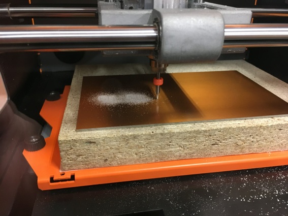
Milling stepper motor board
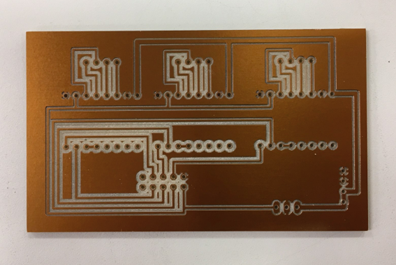
Milled stepper motor board
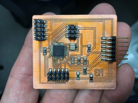
Final stepper motor board
Stepper motor board
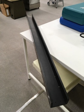
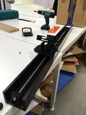
Partly assembled camera rail body
Electronic holder
Electronic cradle
Electronic cradle, assignment 2.
Electronic holder
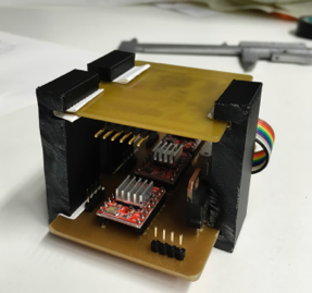
Electronic holders and electronics
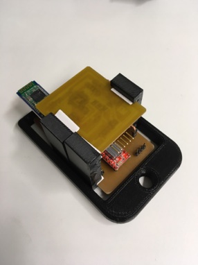
Electronic holders, cradle and electronics
Whole electronic package in rail body
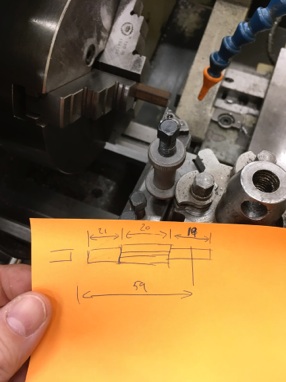
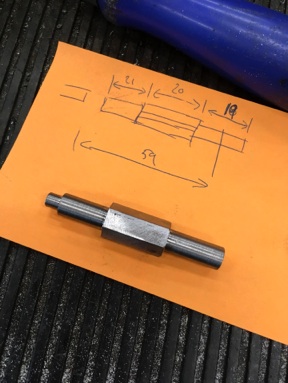
Machining camera head tilt axel
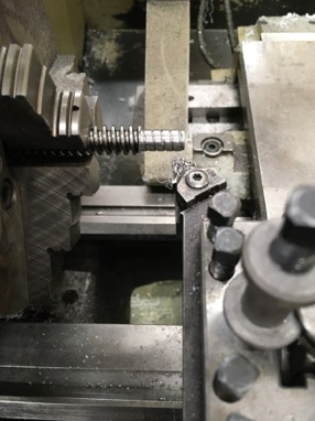
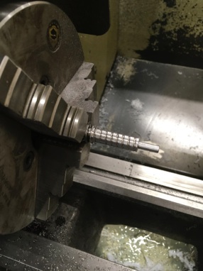
Machining camera head main axel
Assembled mechanics
After assembled mechanics I started to thinking how to use my electronics and also camera rail. I decided to drive my camera rail at first by using transformer and later use battery (when get proper battery). Also on/off switch connected when using battery. With transformer there is no idea to use on/off switch.
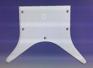
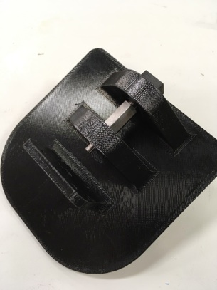
Final leg 3D model
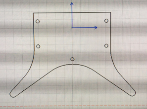
Final leg vector drawing
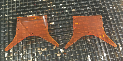
Cut legs, Acrylic plastic
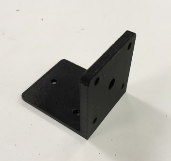
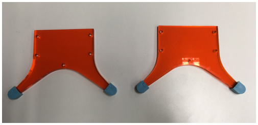
Final legs with casted plugs
Assembling of camera rail
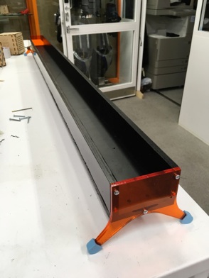
Assembled camera rail
Assembled camera rail with legs
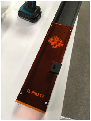
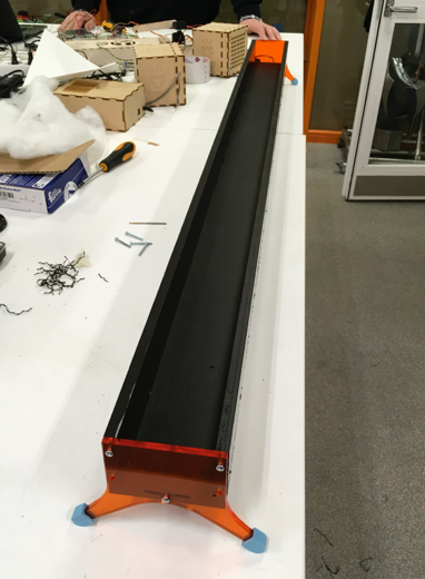
Assembled camera rail with electronic protecting shield and on/off switch.
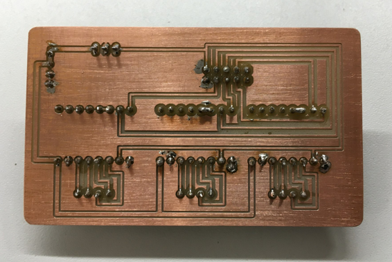
Soldered stepper motor board
I notice that electronics are loose parts in camera rail so I designed electronics holders and cradle for fitting electronics tightly and compact package to camera rail.
Camera head tilt axel
Assebling mechanics
Assebling mechanics
Camera rail assembled (without legs)
EAduino board board view
PROGRAMMING
I started programming by testing simple stepper motor program with Arduino so I know that all motors worked and I have correct base code for motors. Also I test motor speeds and different step modes (Single, Double, microsteps and interleave). I chose double steps best for main axel and camera turn, microsteps are best for camera head tilt. Then I continued to making Arduino program that moves main axel in sequences and give 3 mm movement to camera head at once.
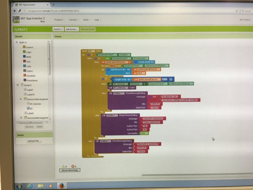
Then I started to learn how to use MIT app inventor 2 to create an app for android phone to control my camera rail. App inventor 2 was easy to use when get basic idea of it. Just drag and drop app object give names to objects and determinate colors to them. Another side of app inventor was ”coding” in blocks site. It worked also by drag and drop style when you drag tiles which tell what objects should do. I build my app very simply and used bluetooth as a connection type. Then I give characters which app send to serial port when button is pressed.
I build app so that there is bluetooth connection button and signal color for bluetooth connected and not connected state. Then there is buttons for all motors manual control. Last buttons are timelapse loop start and stop buttons. So basic idea is to drive camera head to start position manually and then start timelapse loop for photgraphing.
Last part was modify Arduino code so that it understand commands which Android app send to serial port.
Camera movement settings depend on what kind of video you want to shoot, I used first 3 mm movement but it looked too big for near camera located object and video looked like jerking
so I drop movement to 2 mm on later tests. With landscapes 3 mm could be ok. Also I took photo every 7 seconds for test shoots
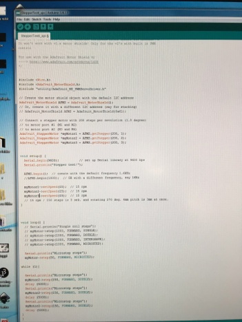
Arduino code
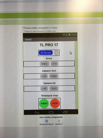
App layout in app inventor 2
Bluetooth tiles in app inventor 2 ”blocks”
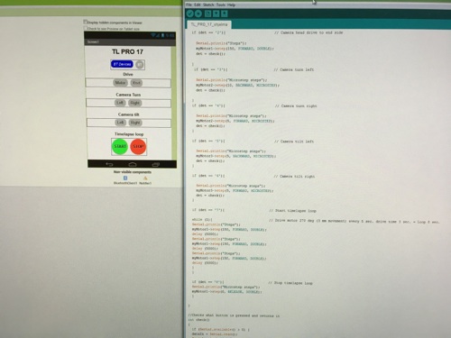
Arduino code and android app
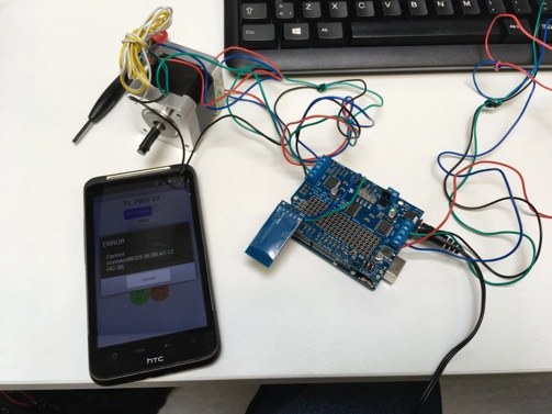
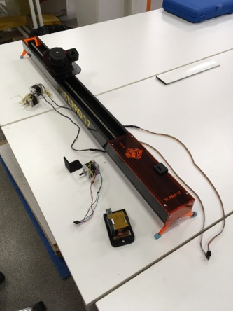
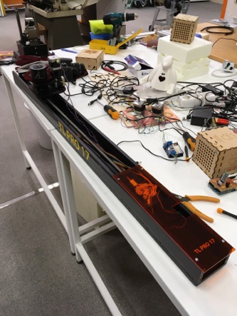
Testing android app with arduino and bluetooth connection
Camera rail set to taking timelapse
FINALLY PHOTOGRAPHING
Final thing was test my camera rail and try to find out is it working correctly. I put it to test with very basic settings:
-
-3 mm movement
-
-motor 15 rpm speed, 270 deg at once -> 3 sec movement time
-
-camera remote settings photo interval 8 sec.
-
-first photo delay 6 sec.
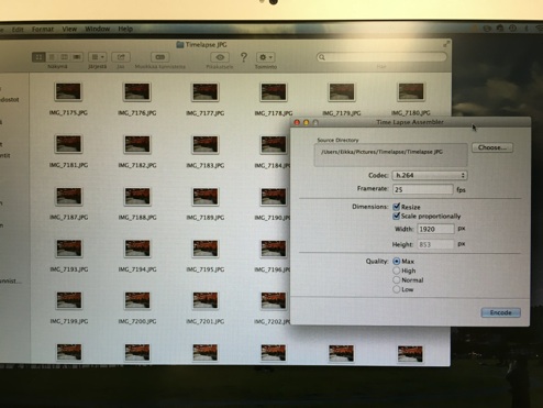
I noticed in first place that calculated 3 movement time of camera head wasn´t correct because after 5-10 photos camera head start to move during taking a photo. Explanation was that movement time wasn´t same than calculated time so I need decrease photo interval to 7 seconds after that it started to work correct rhythm. I took first timelapse video with my rail in our Fab Lab. I took 305 jpeg photos and made video with Time Lapse assembler.
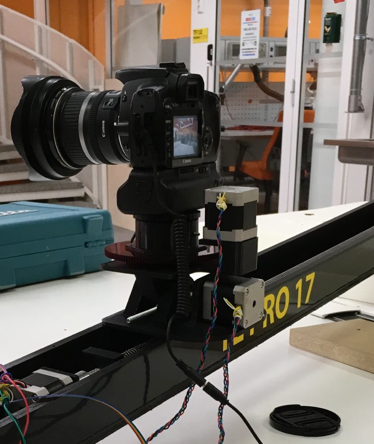
Camera rail during timelapse loop
Selecting photo for Time Lapse Assembler
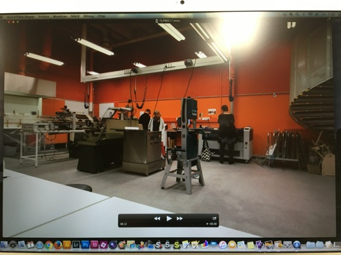
Timelapse video
There were lot of problems with making anroid app and arduino/EAduino connecting to each other. Especially with reading serial port. It looked that android app worked correctly but arduino didn´t got any commands from app. I tried to debug it several days but it not worked at the end. Only when I used ”ready” programs for driving stepper motors camera rail worked correctly. There are no more time to use debugging before end of FabAcademy so connection problems and other development things have to leave to do later. I transfer arduino tested program to my own made electronics and started to test camera rail timelapse photography properties.
BILL OF MATERIALS
My final project materials are (FI = found from fabinventory, NFI = not in fabinventory):
-
-Acrylic plastic, FI, 0.4 m2, 18€
-
-3D print ABS filament, NFI, 500 cm3, 15€
-
-Vinyl sheet, 0.04 m2, 0.16€
-
-10 mm thick (1400x600 mm) PEHD board, NFI, 0.9 m2, 89€
-
-3D printer filament ninjaflex, NFI, 10 cm3, 0.5€
-
-bearings 6000-2RS (3 pieces), NFI, 15€
-
-11 mm thick hex rod (for tilt axel), NFI, 3€
-
-Thrapetzoidal rod 1000 mm M14 (pitch 4 mm), NFI, 11.90€
-
-Thrapetzoidal nut M14, NFI, 7.90€
-
-Nema 17 size stepper motors (3 pieces), FI, 53.85€
-
-Stepper motor axel connector 5 mm to 5 mm (2 pieces), NFI, 6.80€
-
-module 1, 21 teeth gear, NFI, 9 €
-
-on/off switch, NFI, 1€, Free - I found one from broken old machine
-
-casted rubber plugs for legs, NFI, 4cl, 1€
-
-4 mm metal rod (for locking camera mount to camera head), NFI, 0.5€
-
-Camera screw 1/4”, NFI, 3.90€
-
-M4 screws (14 pieces) for legs and protecting shield, NFI, 0.6€
For electronics:
-
-Bluetooth module, FI, 11.99€
-
-ATmega328, FI, 2.87€
-
-resonator 16 MHz, FI, 0.25€
-
-resistor 1k (2 piece), FI, 0.02€
-
-resistor 2k (1 piece), FI, 0.01€
-
-resistor 10k (1 piece), FI, 0.01€
-
-resistor 0k jumper (2 piece), FI, 0.02€
-
-capacitor 1uF (2 piece), FI, 0.1€
-
-capacitor 10uF (1 piece), FI, 0.04€
-
-PinHD 2x5 (3 pieces), FI, 1.8€
-
-PinHD 2x3 (1 pieces), FI, 0.6€
-
-PinHD 1x4 (4 pieces), FI, 1.8€
-
-PinHD 1x6 (1 piece), FI, 0.6€
-
-Linear regulator 12V ->5V (1 piece), NFI, 0.32€
-
-wires, approx. 60 cm, 2€
later (additional):
-
-li-po battery 12V, approx. 30€
-
-battery connectors, 0,5€
-
-Android phone (now I loaned phone for testing), used 15€
I release my final project under Creative Commons Attribution 4.0 International Public License™
Summary of my final project is that there are many things that could have done better mechanics work and look pretty good to me. Also electronics production when well but there are lot of problems with programming or more accurately with coding main program for camera rail. I estimate total costs of my project components 264,94 euros on list prices but it is hard to calculate because I have used many leftover components and material from our lab storage. Additional components rise total cost to 310,44€. So my first estimation in assignment 17 is little bit underestimated but like I mentioned there are leftover parts in my project. Our Fab Lab staff Antti Mäntyniemi and J-P Mäkelä have given many useful tips and advice me during electronic design and making final code to camera rail but in last hand I have made all final project steps by myself. Program wasn´t difficult but there were always a new problem after another (with connections or code it self). I have quite clear idea what to do and when during whole spring. Anyway these unexpected problems with coding took too much time. Time handling was really big issue to me for during whole project because I have normal day job to do and also at the evenings are really hard to arrange any time for final project or weekly tasks. So there are lot to improve with my final project but I´m happy that I get it to this point during this spring really...really tight schedule.
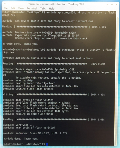
Programming EAduino board
Last minute update: I found out a problem which caused connection errors between Android app and my electronics. It was a broken bluetooth module. All connection problems was module fault. It connect correctly to phone but commands didn´t went through. I changed bluetooth module and everything worked correctly at last. Now everything working fine so I can continue developing app and other details to get smoother and better timelapse videos.