Assignment 3

Computer-controlled cutting
I opened earlier made electronics protecting plate pdf file and printed it using our FabLab Epilog laser Fusion 75W cutter as a printer. I used see through orange Acrylic plastic as a material.
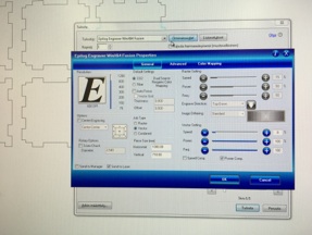
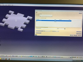
Using laser worked so that first you need to open your pdf file (which I made in assignment 2). Then just click pdf reader print button and select epilog engraver to printer. Open printer properties when you get menu as a seen picture below. In properties menu you set desired cutting and/or engraving values. Some values can be found from Epilog user manual but best values comes when making experiments with different material. Some values from user manual are good starting point but couple times there were major mistakes by manual recommending way too high values. So I wanted to cut and engrave so I select Job-type as a combined and then set cutting and engraving values. Cutting and engraving values are based on my earlier cuttings and engravings with same material. For Engraving I used 50% speed and 35% power. For cutting values are 8% speed, 100% power and 100% frequency. Then click OK and next window PRINT button and your job will be send to laser.
On laser after you have placed your material to cutting table you have to set origin of your cutting/engraving job. Starting point is left top corner of your job. So move your laser printing head and its laser pointer to desired origin by using laser joystick and set origin by clicking a joystick. another thing you have to set is focus point of laser. It can be set automatically or manually. Automatically it can be set from properties menu by setting a material thickness but laser wont know it own location so if someone has set focus manually earlier setting focus automatically might end up to breaking printing head. So automatic focusing is recommended only just after starting the machine. For manual focusing there is a triangle that placed to hang to printing head and by using the joystick cutting table move up and down. So table need to move so that triangle edge will touch to material surface and then correct focus set by clicking the joystick. Ok, when focus and origin has set you need to select your job from laser job menu by using the joystick and when you have select your own job just press GO from laser control panel and cutting/engraving starts.
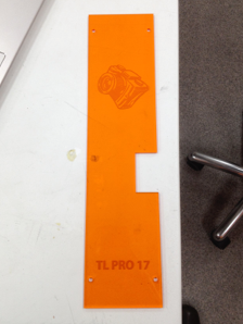
After cutting I just removed protecting surface from Acrylic plastic and my part was ready.
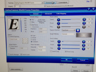
Properties menu for Cutting and Engraving values
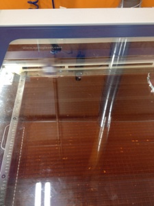
Cutting in action
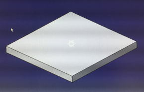
Finished plate
This week we cut something with laser cutter and vinyl cutter. Both machines are quite familiar for me so I manufactured some parts to my final project. With laser I cut electronics protecting plate and with vinyl cutter I made ”cool” tapings to sides of my final project body.
LASER CUTTING
VINYL CUTTING
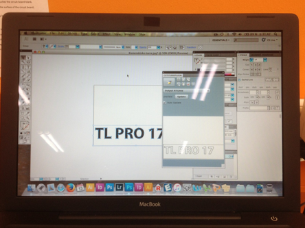
Cutting design in Illustrator
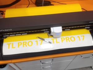
Cutting in progress
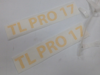
Cut and cleaned vinyl
Final tape with transfer tape on it
At this point I decided to name my final project to TL PRO 17. TL comes from timelapse photography in which my final project product is designed. I used Illustrator to design cuttings to a vinyl sheet. I need to load a Roland cutstudio plug-in to my computer to make possible direct cutting from Illustrator. I found out plug-in easy to use and very functionally. I just make text with text tool added border lines with rectangle tool and press cut from cutstudio plug-in. Plug-in ask which cutter is in use and after selecting cutter I have only press ”cut” and cutter start to cut my design.
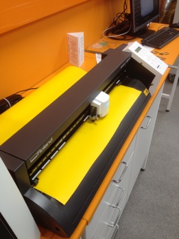
We have Roland camm-1 GS-24 vinyl cutter in our Fablab so I use it as a machine. So basically what you have to with vinyl cutter is set material (vinyl board) in cutter lock pressure rolls to vinyl sheet and switch vinyl cutter power on. Then just select option edge from vinyl cutter control panel and click enter button when vinyl cutter find edge of vinyl sheet. Then just press cut from Illustrator plug-in like I explained above.
After cutting I get out from cutter vinyl which have cut lines but still looks like solid vinyl sheet so I needed to ”clean” it what means that I needed to remove extra vinyl surface away from sheet. I used tweezers for accurate cleaning of extra vinyl. When I was ready of cleaning process I cut my piece of vinyl away from bigger sheet and attached to it transfer tape helping to transfer fonts from sheet to my camera rail body. I made to cuttings one for each side of camera rail body.
Parametric model
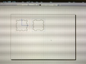
There is also a task to make parametric model which take to account material thickness and laser kerf. As a part I chose to make a 50x50x50 mm box. You can change material thickness or laser kerf in function menu and model changes slot dimensions to all slots as well. I made my box with CATIA and used function tool for making parameter model. With function tool you set all dimensions which you want change by setting dimension in function menu. By setting that dimension (material thickness or kerf) it will be change to all slot dimensions. I made three different walls (bottom/top, side1 and side2). But I show below parametric function tool by explaining it with bottom/top plate. After modeling I made drafting from models and saved it to pdf then I opened pdf in Illustrator and changed stroke width to 0,02 mm which our lab laser consider as a cutting line width. Saved again to pdf and put it in USB memory stick and went to laser to cut it.
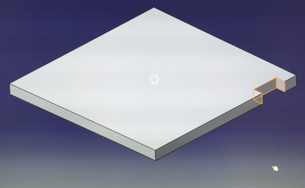
Base plate 50x50 mm
”Mother” slot
Pattern tool
Bottom/top plate
Side plate
Drafting
Stroke weight adjustment in Illustrator
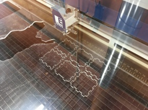
Cutting
Cut settings
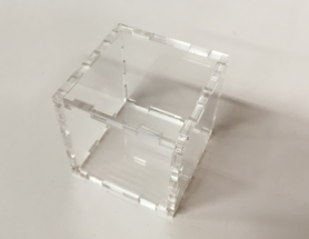
Final box
Group task
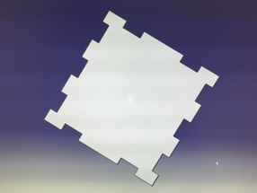
We have also a group task to cut something and figure out laser beam diameter (=kerf). Our group was me and Yrjö Louhisalmi from our lab. We decided to cut ”fork” in zero (clearance) dimension and measure it. After that we tried different (fork width in mm) dimensions and made research how they fit together. We draw cutting model with Illustrator and then saved it to pdf for cutting. All dimensions are design dimensions so them are marked as them are on drawing. Parts are made from 3 mm thick acrylic plate. We also engraved dimensions to parts so we cannot mix samples.
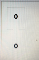
Zero dimension model
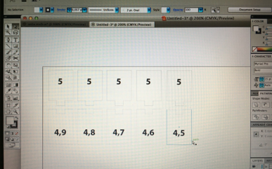
Research models
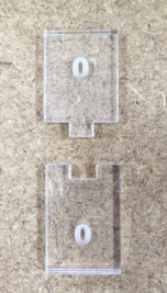
Zero dimension part
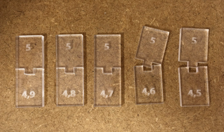
Research parts
Zero dimension part cut as a one part only one separating line and design dimension was 5 mm with no clearance (0 mm). We find out when measuring part that slot was 5,21 mm and plug 4,88 mm so clearance was 0,33 mm. So we figured that 0,4 mm smaller slot should be correct for push joint. With trying research parts we found out next things:
5 - 4,9 Too loose, big clearance
5 - 4,8 Small clearance and not attached firmly
5 - 4,7 First snap on joint but get loose after couple fasten-unfasten loops
5 - 4,6 Push joint, have to use some force (Best solution!)
5 - 4,5 Too tight, by using force a joint can be done but parts cannot mount to same level
Using bigger negative clearances will cause breakage of acrylic plate.
So we find out that using 0,4 mm push joint should be best with these thick acrylic plate. Thicker material it would be little less because cutting edge is not straight. It has little bit of chamfer on edges. So we figured out that correct focusing and 2” lens in our Epilog 75W CO2 laser laser beam diameter (=kerf) is about 0,2 mm.
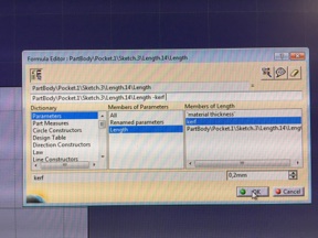
After drawing a sketch of slot there is a function menu button (Fx) at the bottom tool bar. Click that and add a new parameter (material thickness) also add another (kerf) parameter. Set both type to lenght. Then go back to slot sketch choose dimension that you want to set as a parametric dimension. Click it on right mouse button and choose lowest option lenghtXX (XX is number of dimension it changes all dimensions in your part) then there open a another option menu where you choose edit formula. Then you set which parameter you want to affect to this dimension (like I set kerf below picture). I set original width of slot - kerf will be final dimension. Then I made a slot with pocket tool and multiply it by using mirror tool.
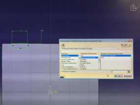
Sketch and edit formula menu
Edit formula menu
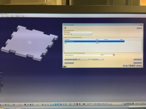
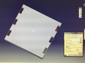
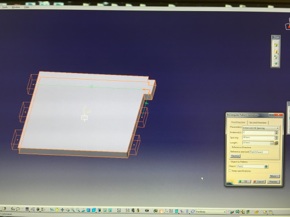
Material thickness set to 3mm
Material thickness set to 7mm
After you have set all desired dimensions to parametric you can change model all dimensions by opening function menu from bottom tool bar and selecting desired parameter (like below I choose material thickness) and changing its value so it affect to all model dimensions.