Assignment 7

computer-controlled machining
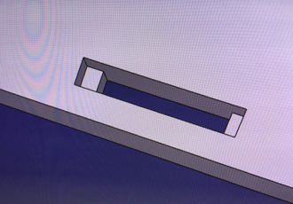
Computer-controlled machining task I decided to make my final project body by milling it with our CNC router. I thinking about many different solutions how to make body of camera rail but I end up making it by milling parts from PEHD plastic plate. Also how to attach body parts to each other I went through many ideas and search solution also from wooden timber joints. Finally I end up making body parts as a shown in next steps. I end up a design which leaves no signs of clips to outside and hide pockets to under the base plate.
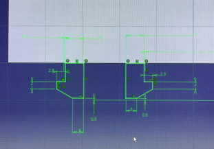
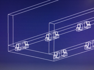
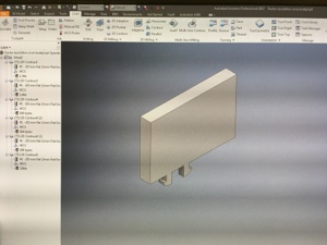
Designing clips to my rail side walls. Sheet is 10 mm thick and clips are 5 mm thick
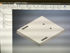
Designing pocket for clips. Pockets hide clips totally in position that body is designed to use.
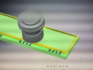
Clip attached to its pocket
Assembly picture
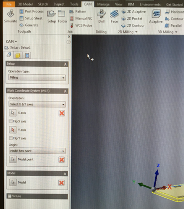
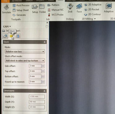
After designing I need to make CNC code to router. So I saved parts that I have designed with CATIA to step files which I opened in Inventor. In inventor I used HSM CAM to make CAM paths and CNC code. Post processor configuration for HSM is made by J-P Mäkelä in our lab. I made CAM paths in next steps shown below. First define operation type and coordinate axels to your model (directions and location depend on machine). Operation milling -> set milling. Coordinate axels (correct direction on your machine). Define stock part size on HSM for your work (material piece size) in real life material piece could be bigger (this is only for HSM screen view). I leave it little bit bigger on sides so I saw cutting of edges in simulation mode.
Setup define operation type and coordinate axels
Define stock size and offsets
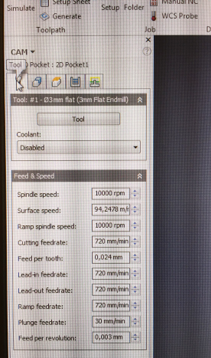
Then opened new pocket (top tool panel 2D milling -> 2D pocket) and defined tool and parameters for tool. I used 0,024 mm/tooth feed with 10000 rpm spindle speed so cutting feed was 720 mm/min. As a plunge feedrate I used 30 mm/min but it could have been higher for example 100 mm/min.
Tool and its parameters
Choosing features to make pockets
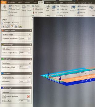
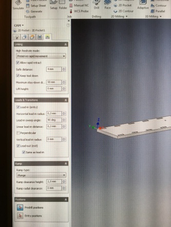
Defining planes (top, bottom, clearance and retract)
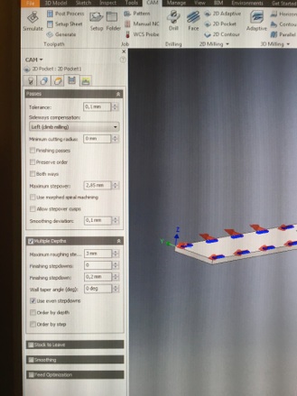
Defining milling type, stepovers and cutting depth.
Defining lead-ins and lead-outs and also how to tool penetrates to stock.
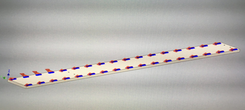
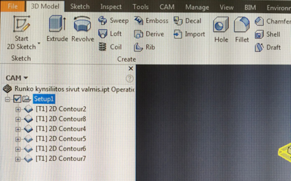
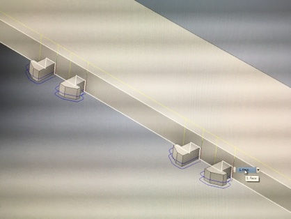
I repeated these steps to all shapes of bottom plate and also side walls so finally I got two CAM files. In bottom plate I used pocket tool for clip pockets and bearing holder holes. Clip pockets I made in two steps first bigger pocket 5 mm deep cut and then smaller pocket through the sheet and at last I made contour for milling bottom plate off from bigger stock sheet.
Side walls I made so that first I made contour to thinner sheet 5 mm from clip positions. After that I milled shape of clips and then milled straight wall between clips. Finally I milled bottom plate off from bigger stock sheet. I used contour path for all side wall shapes.
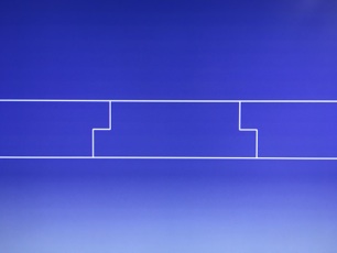
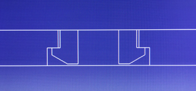
Contour path for clip outlines.
Side wall contours
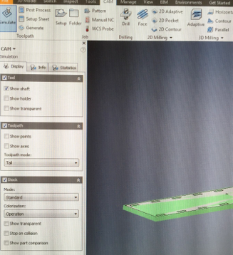
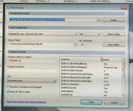
When both CAM files were ready I simulated files and checked that path went correctly. After simulation I just post them to CNC code which is ready for milling. Post process files to CNC code by pressing ”post process” from top tool panel and chose folder where I want my CNC code, chose used post processor, setting name for my CNC code and press ”post”. Post processor made ready CNC files to folder that I have chosen.
Setup for simulation
Side wall simulation
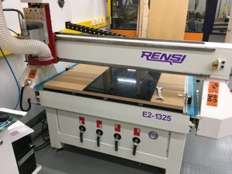
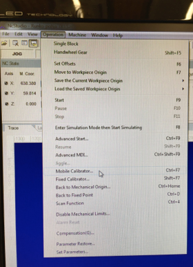
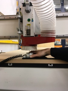
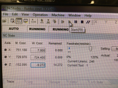
I opened router software NcStudio and placed PEHD board to vacuum table of router. Vacuum pump was broken so I used traditional methods to attaching board to the table. I attached my PEHD board to big and thick (20 mm) mdf board by using screws and screwdriver. Mdf board I attached to router table from edges by using screw fasteners (seen on picture below). I used our lab Rensi E2-1325 router. First I needed to define origin (X and Y coordinates) of my model and zeroing that to NcStudio. I moved X and Y coordinates to desired position from right upper corner tool panel in NcStudio. I zeroed X and Y by pressing X and Y W.coord button when tool was desired X/Y -position and NcStudio set X/Y coordinate as a zero point. Then I zeroed also Z -axel with automated touch pad by setiing touch pad under tool and pressing operations -> machine calibration -> Ok. Tool lowered and touched gently to touch pad. After that it knows tool length and software saved it to Z-axel zero point. I add 0,1 mm to Z -axel zero point because vacuum table was broken and there is a risk that part will move during last milling routes. Adding 0,1 mm make sure that part will stay a part of stock board but it can be easily removable after milling. After all setups are done I loaded nc-code to NcStudio. It can be simulated in NcStusio if there is a doubt that nc-code is not working correctly or just make sure that coordinate axels are correctly defined.
Board and router
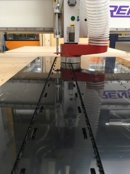
Milling of the bottom plate on process
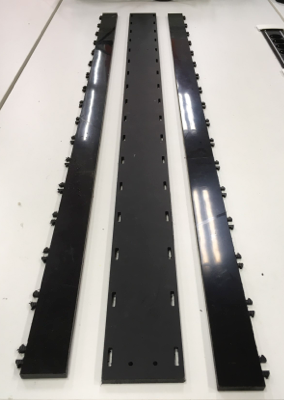
Final parts
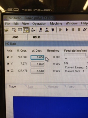
Zeroing X and Y coordinates
Zeroing Z -axel with mobile calibrator
Zeroing Z -axel with touch pad
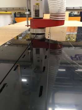
After loading nc-code just press start to start milling.
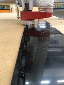
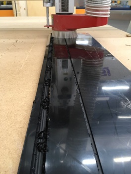
Milling of the side wall on process
I didn´t assembly parts together because this snap on joint is no disassembly kind joint. So when it is once assembled it can not disassembled at least without breakages. This is a part of my final project and there is possibility that I need to do some adjustments to bearing unit assembly locations or assembly layout so those adjustments are easier to make to unassembled parts. Assembled camera rail body you can find at the end of Fabacademy from my Final Project site.
There is a two milling tasks which I used pocket and contour. Pocket is part ”internal” pockets and contour is for outlines (edges) ”contours”. With pocket tool you need to select pocket which you want to mill from your model and then define parameters for milling. First have to set milling heights (planes), bottom and top height for milling top and bottom. Feed height - height where feed starts, Retract height - height where tool retract after milling turn, Clearance height - height where is save to move tool from place to another.
Milling is which way you approach to material edge (use climb milling if you don´t have good reason for other method), stepovers (how close routes are to each other) I set it 2.85 mm because tool diameter was 3 mm and with cutting depth you define how depth tool cutting at once.
Post processing
TEST PART
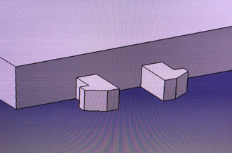
I made also a test part before I milled final part. I milled only piece of bottom plate and one clip of side wall. I used same settings and parameters than final part but I only want make sure that clip will work correctly. Milling test part went well but I noticed that my clip joint was one time assembly because PEHD material was so soft that if you tried to open the joint clips will break. So after that I knew that when I assembly my camera rail body it will be immediately final assembly. By making test part I got confirmation that my clip model will work. Below is pictures of test part in HSM. I add this part to assignment a little later after I show test parts in wednesday lectures. After lectures someone has taken test parts to somewhere so I don´t have picture of real test parts.
Test parts in HSM.