Project Development
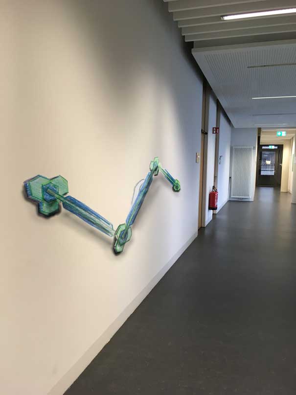
My first idea was a walking handrail. In the first few weeks I was searching for how it would look like and how it would move, what kind of movement it would perform.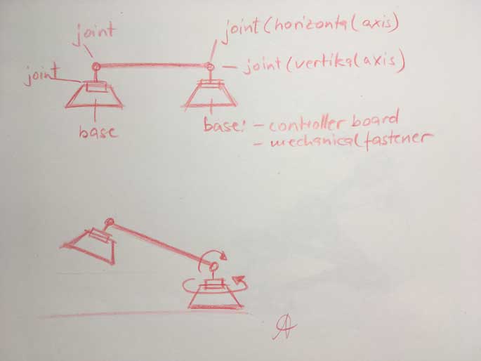
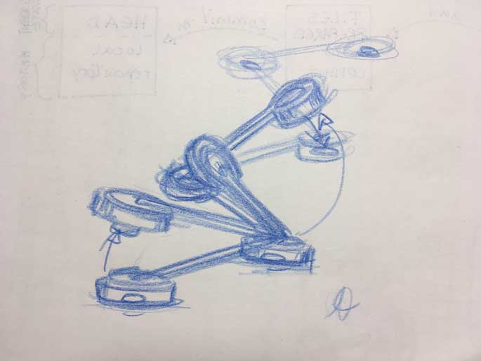
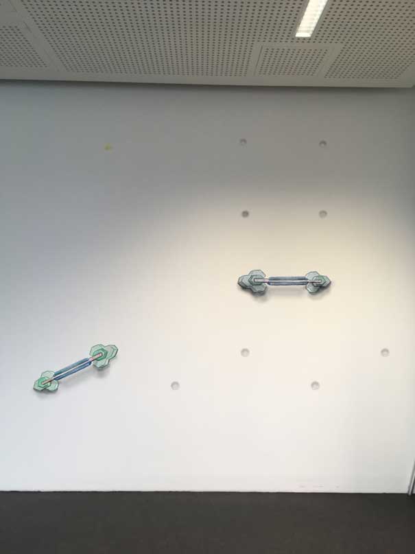
These drawings below were made in the second week computer-aided design, checking out the movement performance on the wall in Photoshop and Gimp.
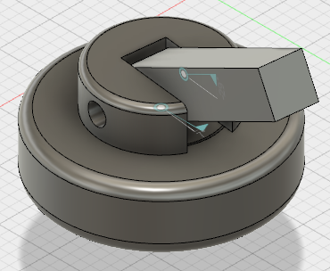
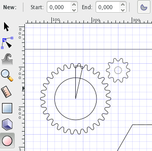
Then creating a rotation movement in Fusion360 and trying out gear constructions in Inkscape:

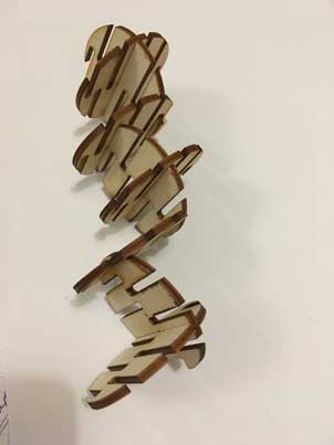
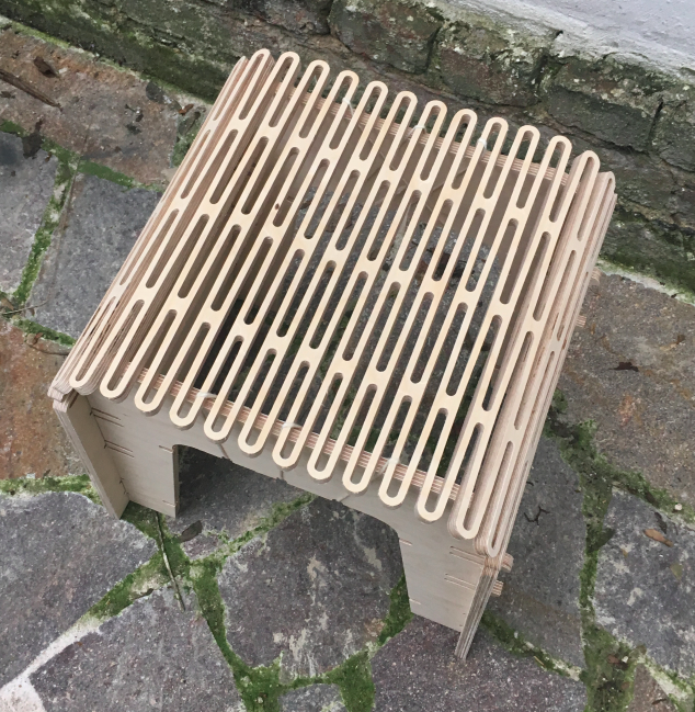
In computer-controlled cutting I was interested in to find out how I can produce a light structure through substraktive methods, in combination with first: flexibility and second: stiffness despite of minimum of material usage.
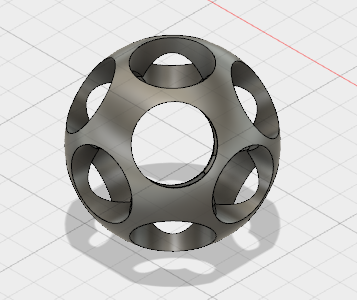
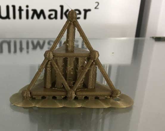
The3D scanning was about how I can print a light structure through additive methods ind combination with stiffness despite of minimum of material usage.
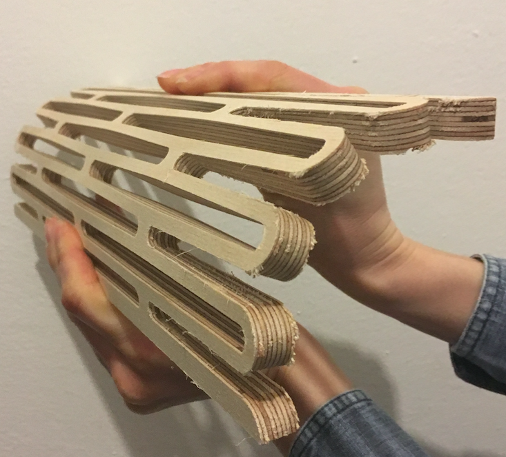
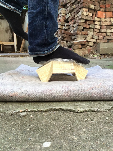
Computer-controlled machining I utilized for experimenting light structures that transform stiff material in flexibel one.
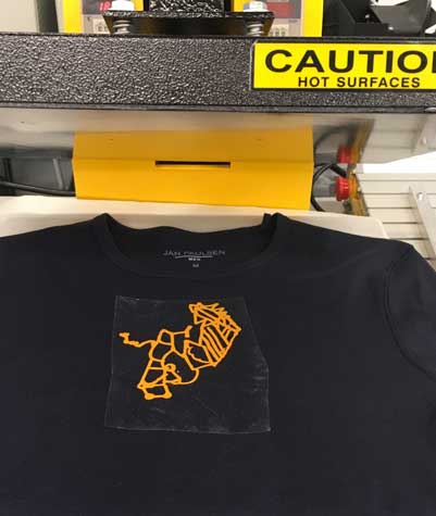
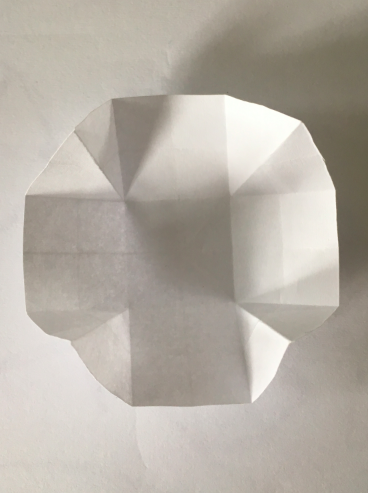
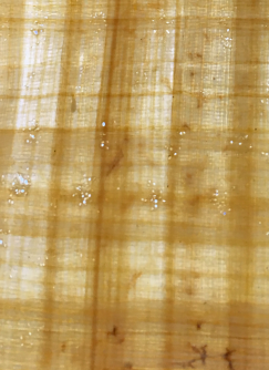
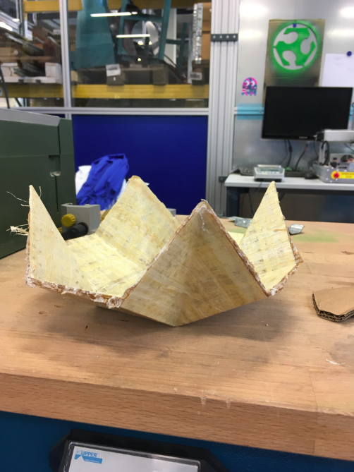
In composites I tried another light weight structure: foldings I used papyrus leaves and jute to create a natural based architectural light weight structure with a lasercutter. I did some strength tests.
During our electronic and programming weeks I´ve tried to find out solutions for the problems and tasks I was going to be faced in my final.
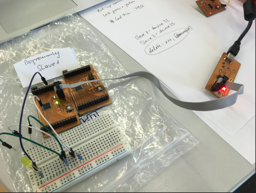
In output devices week I was trying to find out how to controll a motor not only in Arduino but especially in C. As I am very much interested in the architecture of microchips I wanted and want to learn how to program them on the lowest level as possible. Finding out the register address in Atmels Datasheets to switch on a pin was very interesting for me. I´ve looked up in online tutorials for assembler language to understand how a chip is working, and then I started to learn C language, nearly everyday I was learning C from books or online tutorials. With the help of one of these tutorials I found out how to find the right addresses in Datasheets, how to calculate and programm the angles the motor has to perform.
                        //main.c ATmega328 Program

                        #include <avr/io.h>
                        #include <util/delay.h>

                        #define F_CPU 16000000
                        #define BUTTON_PRESSED	(PINC & (1<<PC6))
                                                // check for button press
                        typedef unsigned char  BYTE;
                        typedef unsigned short WORD;

                        int main (void) {
	                           // declare PB1 as output pin.
                               //This is where the motor is connected
	                       DDRB = (1 << PB1);

	                       TCCR1A |= 1<<WGM11 | 1<<COM1A1 | 1<<COM1A0;
	                       TCCR1B |= 1<<WGM12 | 1<<WGM13 | 1<<CS10;
	                       ICR1 =19999;
	                   // main loop

	                   while (1) {
		                      OCR1A = ICR1 - 800; //18000
		                      _delay_ms(100);
		                      OCR1A = ICR1 - 1600; //18000
		                      _delay_ms(100);
		                      OCR1A = ICR1 - 2600; //18000
		                      _delay_ms(100);
		                      OCR1A = ICR1 - 1600; //18000
		                      _delay_ms(100);
		              }
	               }
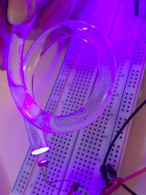
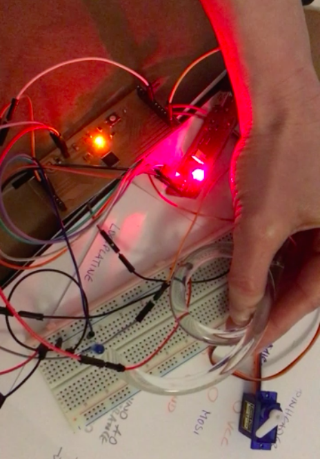
In Input Devices week I thought about a communikation between two boards via light. One pcb in each foot and an acrylic pole as communication channel. But it is also possible to you use it as a general input instead of a start button for example.
In Networking and Communications I thought about having at least two boards, one in each foot, but at the end I thought this networking principle makes more sense for more then two feeds for example a snake style robot or octopus robot, with one master and for each leg or joint one small board. This is something I would like to develop after my railbot.