Output-Devices
The group-assignments ';mechanical design' and 'machine design' need at least skills for 'output devices'. To get into this topic (to create a board for output and/or input and programm for e.g. a servo motor) we had to design a new board. Our instructor Tobias recommended to create a fabkit. So I decided to see how 'satchakit' from Daniele looks like. Your can find it under the topic 'input devices'. I compared it to eagle schematics of 'Arduino Uno Rev' to find out how his decisions were made. Some I could follow. Some are not clear, yet. I´ll find out. As one of my main interests are didactic concepts I allways look on tutorials, explanations etc. by this perspective. And the hiding behavior becomes more and more strange to me. I know, that one have to study electronics or programming to be able to work professionally in this field, but for beginners it is possible to explain main features as starting points. This is a gap I miss a bit or I just could not find out. In general people believe tutorials are only for specialists, they still haven´t experienced good comprehensible tutorials. There are many nowadays, but for electronics I couldn´t find any that answered my questions I had. Only the german Eagle video tutorial by 'TU Berlin' I used in fourth week 'electronic production' was really satisfying. Now, getting more and more into this topic I get an idea how I would explain it to others. But still I have to learn more...Aleks' Fabkit board based on Satchakit
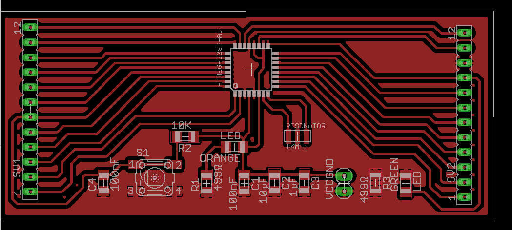
Based on Satchakit I changed the design and took a 16Mhz resonator instead of chrystal back to Arduino's layout. As I need boards fitting into a tube I stretched the board and used female headers. The board is still under construction, the following pictures are just a starting point:
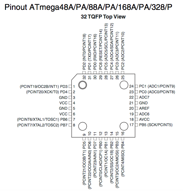
I've used an Atmega328AU with the following pin occupancy. The pin occupancy is the same for 238, 238P,238AU..

Due to some missing 1206 size parts I thought we had in stock, I decided to adapt the footprint to a much smaller size: 0603 we have in stock. Wow, that was an amazing experience. I really like working with a microscope. Still, we are missing 10µF but I placed smd 0603 100 nF instead of 1206.
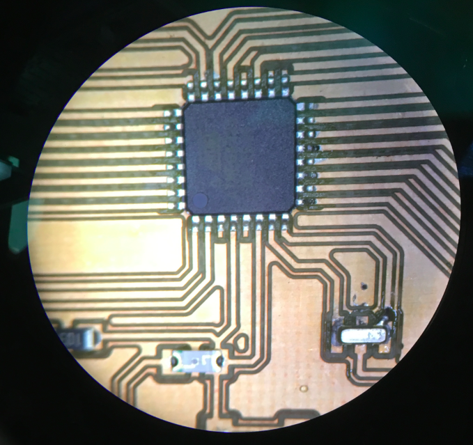
As you can see below the size differenz between 1206 and 603.

Download FabkitAleks schematics2
Download FabkitAleks board2
First Programming in C Blinking Test
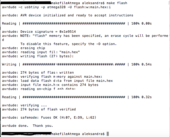
Now, I have to programm my board and see if my board is o.k.: I opend a new folder and put the Makefile and a hello.c-file inside. I had to adapt the Makefile to the new chip: Atmega328 AU. In Engbedded I got the informations to set the fuses. Then I typed
I just got a plain Atmega328. I changed the signature by changing the name in Makefile from (Atmega238P-AU to Atmega328). Then I run the led blinking programm I`ve used for my hello board with some adaptions to initialize my chip. I had to adjust the address for my LED and for the bottom. It worked out very well.
Second Programming in Arduino a Servo Motor
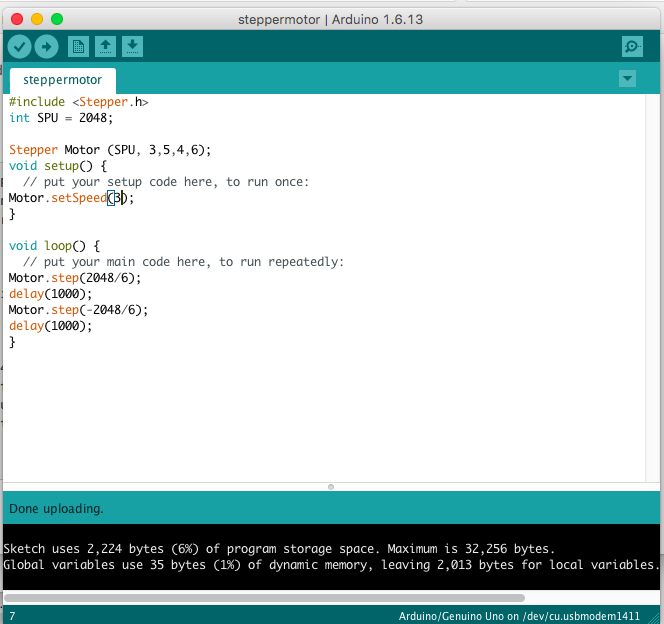
As the initializing worked out and I was sure the resonator is working well I started with my next step, looking for a way to control a servo or a steppermotor: First with ArduinoI`ve used a pre-installed sketch-example for a steppermotor

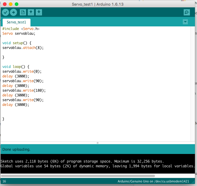
Afterwards I´ve tried the same with a servomotor and adapted it later on my fabkit board:
The way until I could controll my board with Arduino. I had the problem, that a plane Atmega238 is not listed in Arduino' library. That means the programm could not upload any program. If you want to know how I prepared my board for Arduinos Programming please click: here.
                                #include <Servo.h>
                                Servo servoblau;

                                void setup() {
                                    servoblau.attach(8);


                                }

                                void loop() {
                                    servoblau.write(0);
                                    delay (1000);
                                    servoblau.write(90);
                                    delay (1000);
                                    servoblau.write(0);
                                    delay (1000);
                                    servoblau.write(90);
                                    delay (1000);
                                    servoblau.write(30);
                                    delay (1000);
                                }
Please see below my first trial to run a servo. At that time it didn´t work out to controll the speed, even if I could do it with an Arduino Board. I had great problems with the clock device and usb device, working with Arduino software on my board. I couldn´t understand yet, why. But my next step will be to run a servo with plain c.
Programming C
After searching for a way to write a c programm for my servomotor I found a very good video tutorial. It is more a bundle of tutorials from Patrick Hood-Daniel 38.Microcontrollers. There are steps before and afterwards. It was really good for me to understand how a servo is build and how I can read the Datasheet of a Microcontroller. Even if he used an Atmega32, I compared the register settings with the Datasheet for Atmega328 and they were same. In video no. 38 he explains very carefully, how to calculate PWM and make all the settings you need to have the right signals on the right place in the right time. Finally, I had to adapt it to my board and pin situation to get it running.Now, I will explain a bit what I´ve learned from these video lessons:
- See what kind of Microcontroller you have and open the Datasheet for the appropriate group.
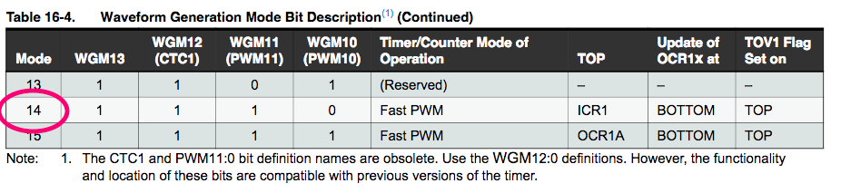
- For Atmega328 you will find on page 132 the section Timer/Counter clock Sources with the chart 16.4 'Waveform Generation Mode Bit Description'.
- In Mode 14 you will find the WGM 10-13 settings for Fast PWM. In 'Top' you will see ICR1 as the peak of counting. Right beside you can find the way of counting to OCR1x from bottom.
- Counter- and Timeline: OCR1A is the counter point where the servomotor has to go.You can set this. For example, one cycle is 20ms long, the counter divides this cycle in 200000 steps and counts () 0 - 19999). ICR1 (19999) is the top point with the counting number 19999. To set the counterpoint for OCR1A in one cycle you should choose a time between more or less 1ms and 2ms not to overstrength the servo motor.That means between 1000 and 2000. Can be less or more, you have to try. The servo is usually describing a 180 degree arch.
- If you want to set OCR1A 800 steps under the ICR1 (top) then you have to define it as a calculation: 19999 - 800 or ICR1 - 800. That means OCR1 is less then 1ms below the peak, that defines one angle your servomotor has to go.
- Now, you have to find out in which Register you can find the WGMs to be able to set them to 1. For this you you have to find the Timer/Counter1 Control Register A and B. TCCR1A is on page 131, there you will find WGM11 and WGM10.In TCCR1B on page 133 you will find WGM12 and WGM13.
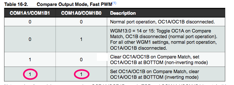
- Now, you have to set the COM1A1 and COM1A0 (Compare Output Mode for inverting or non-inverting Mode), too, in TCCR1A. On page 131 Table 16-1 you can find the settings for this. You have to set them to 1 to get the inverting mode.
- Clock select mode you will find in TCCR1B. On page 134 you will find the Table 16-5 for clock selection. Set cs CS10 to 1 for ' No Prescaling'.
- At least, you have to set Data Direction Register(DDRA or DDRB) to enable your pin channel (here it is B) as output driver.


                        //main.c ATmega328 Program

                        #include <avr/io.h>
                        #include <util/delay.h>

                        #define F_CPU 16000000
                        #define BUTTON_PRESSED	(PINC & (1<<PC6))
                                                // check for button press
                        typedef unsigned char  BYTE;
                        typedef unsigned short WORD;

                        int main (void) {
	                           // declare PB1 as output pin.
                               //This is where the motor is connected
	                       DDRB = (1 << PB1);

	                       TCCR1A |= 1<<WGM11 | 1<<COM1A1 | 1<<COM1A0;
	                       TCCR1B |= 1<<WGM12 | 1<<WGM13 | 1<<CS10;
	                       ICR1 =19999;
	                   // main loop

	                   while (1) {
		                      OCR1A = ICR1 - 800; //18000
		                      _delay_ms(100);
		                      OCR1A = ICR1 - 1600; //18000
		                      _delay_ms(100);
		                      OCR1A = ICR1 - 2600; //18000
		                      _delay_ms(100);
		                      OCR1A = ICR1 - 1600; //18000
		                      _delay_ms(100);
		              }
	               }
Download Makefile for Atmega328. Download Blinking test main.c blinking test for Atmega328.
Download pure C File in Arduino background: ServoPureC
Downlod Arduino file: Servoblau.