Design Process and Design Decisions
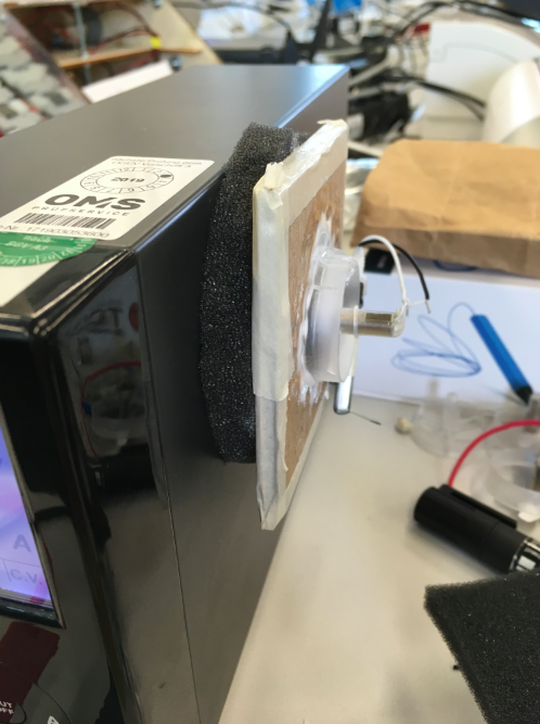
After discovering the broken copter box in our fablab, I thought about sucking and underpressure to reinforce the foot grip. Then I could quit the idea with electromagnet.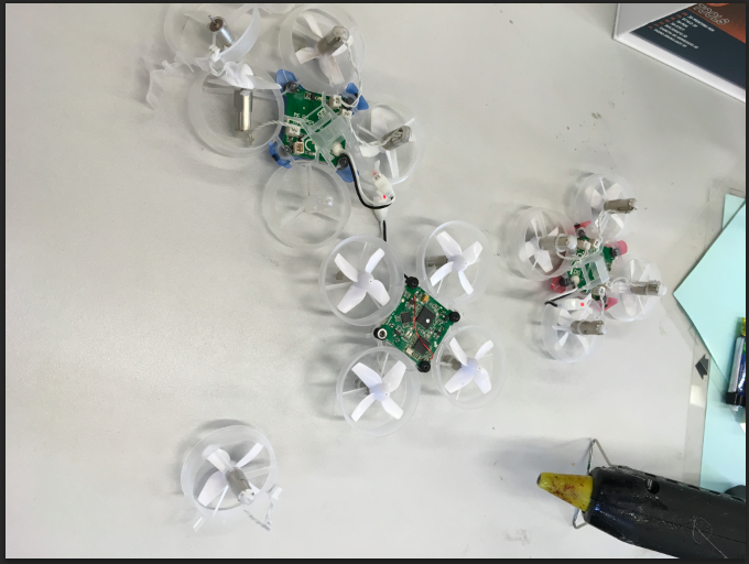
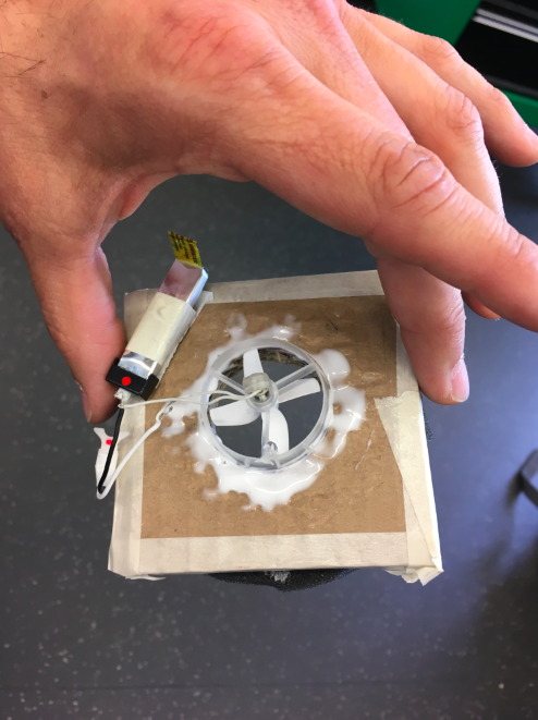
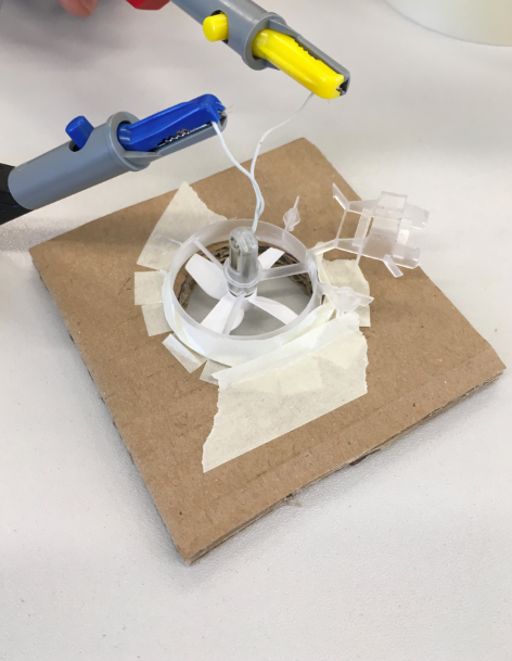
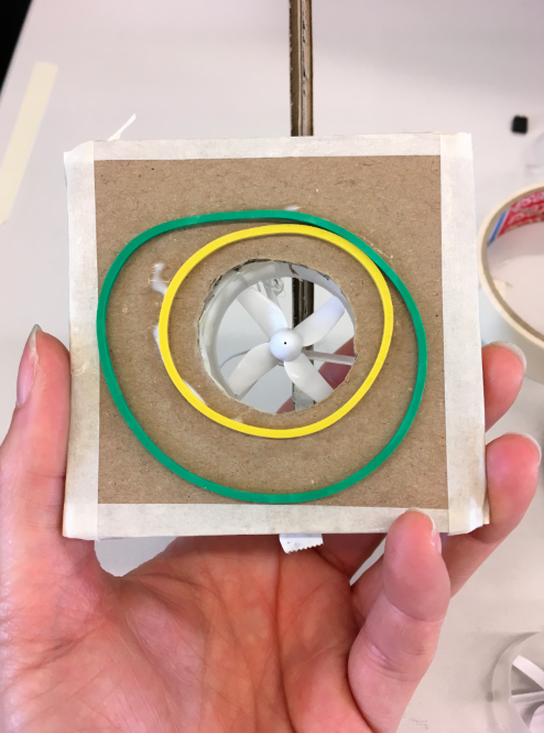
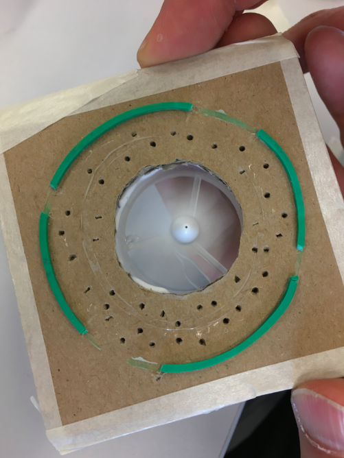
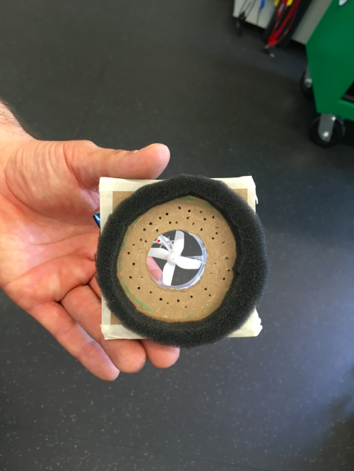
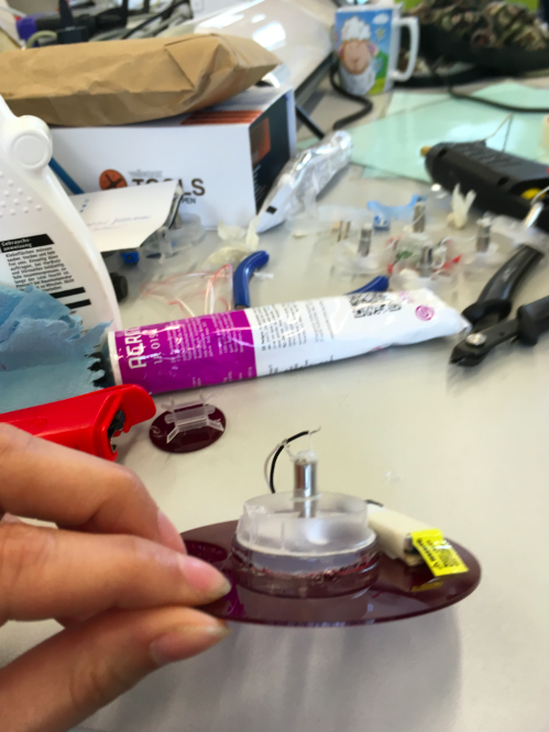
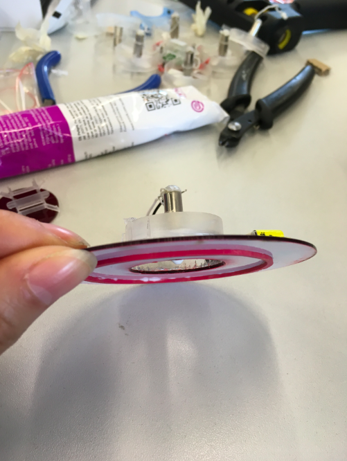
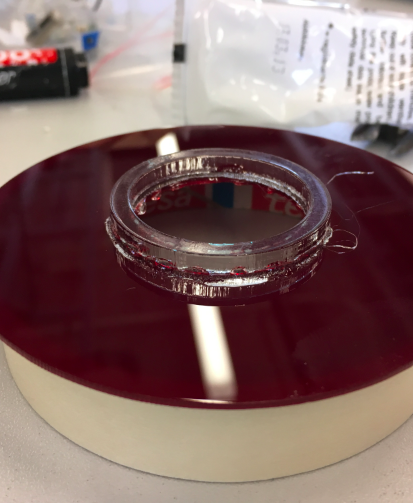
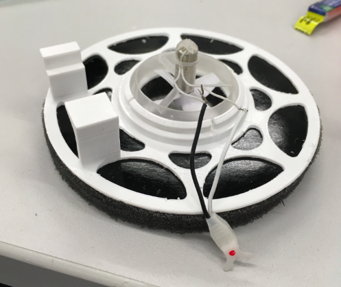
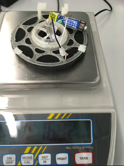
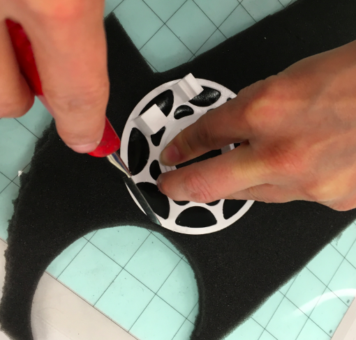
I tried out several types of surfaces and root bases to find out which one is good for creating adequate underpressure. I glue ring shaped bases to discover that they need some more fresh air coming from beneath. Therefore I cut canals into it. Then I thought it would be better to use foam not rubber.
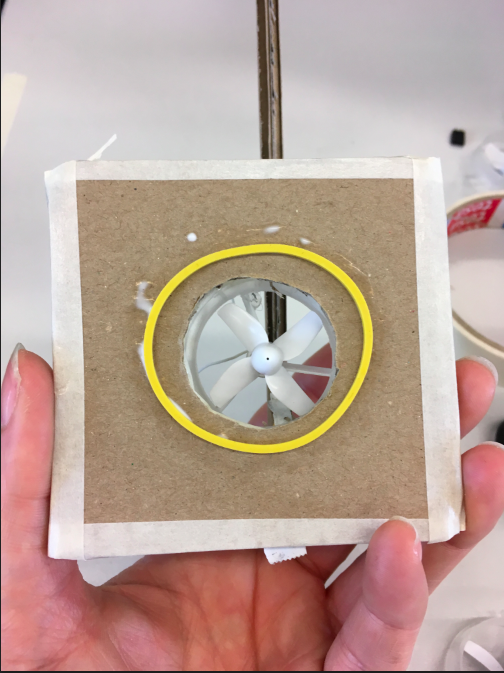
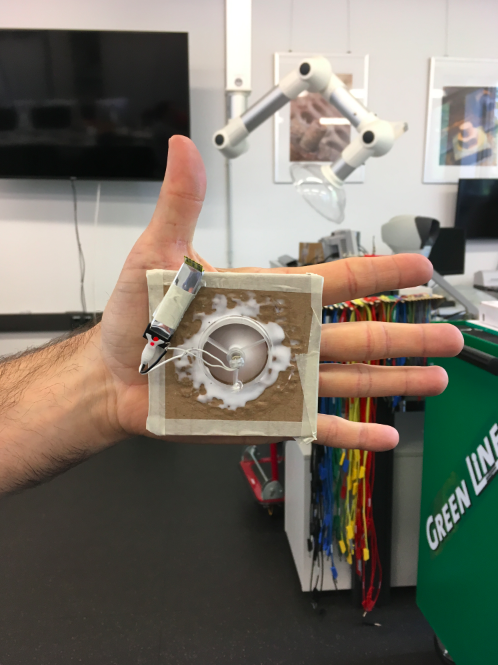
Best material for sticking was cardboard but astonishing enough for me was acrylic wasn't bad, too.
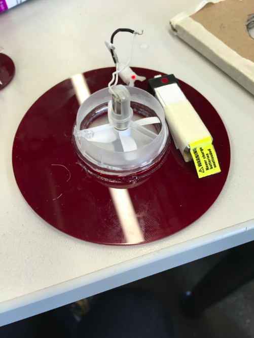
Soon, it came out that I will not need rotating x-axis anymore as the pushing rotors keep their feet sucking to the table and the pivoting rotors were sliding on air cushions.
Design Development
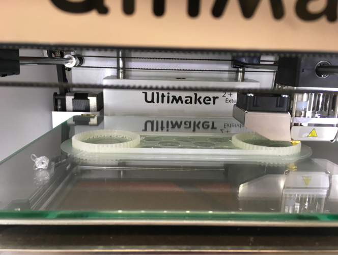
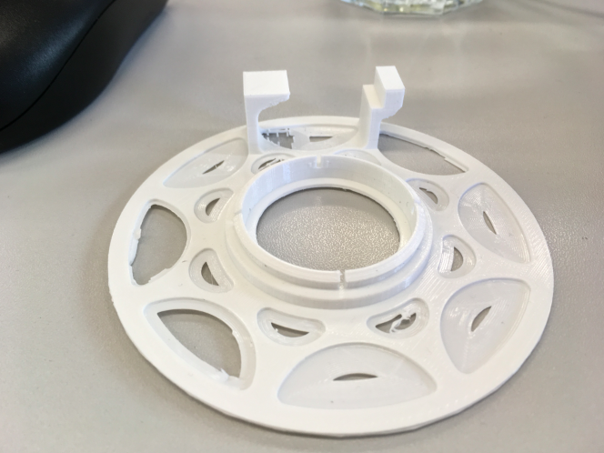
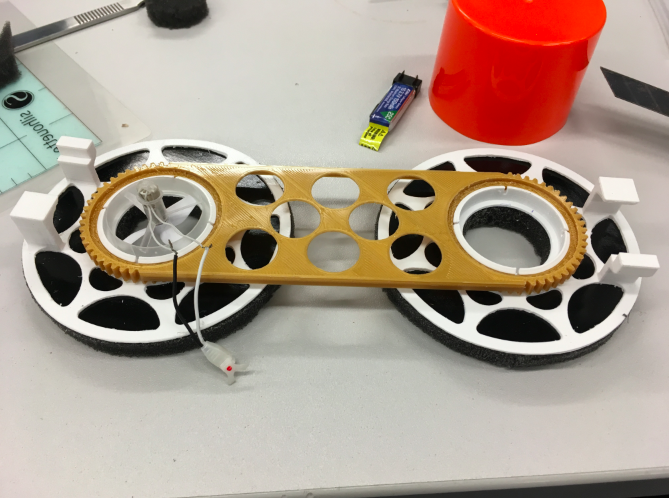
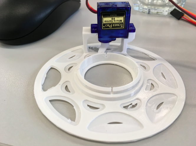
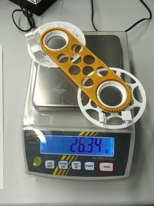
In this first version I looked for two questions. Is it easy to assemble? Yes. Just clicking the travers onto the feet finishs the body of railbot. Where will I put the motors and the pcb? The pcb will be fixed onto the traverse. In this first version the servo motors where planned to be fixed on the feet. It was very important to reduce the weight by designing a light weight structure. In the picture below you can see the weight of 2 feet and one traverse is 26.34 g.
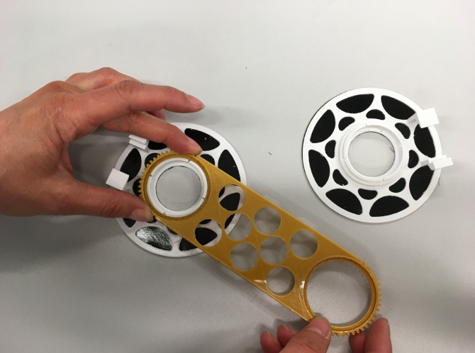
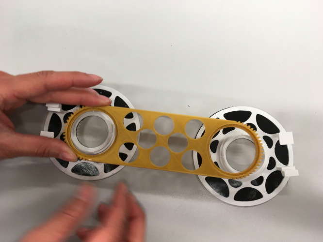
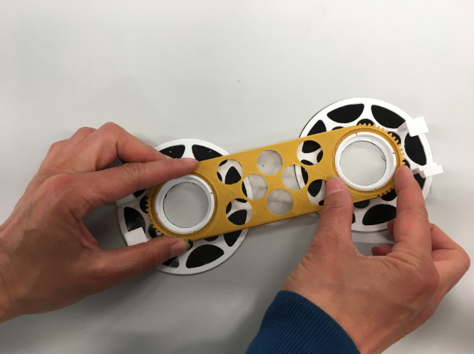
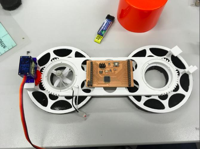
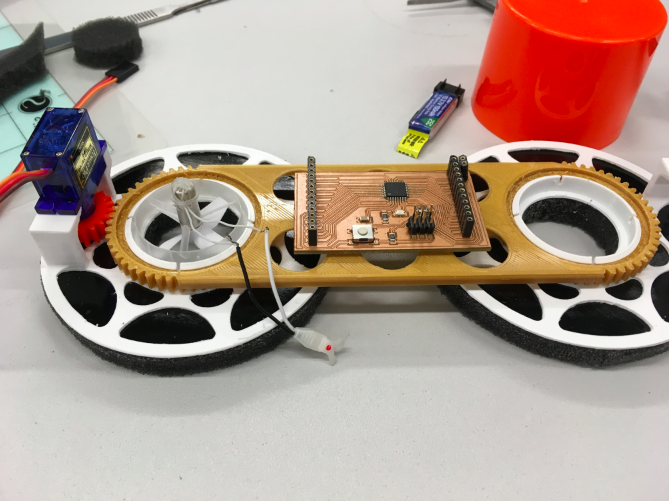
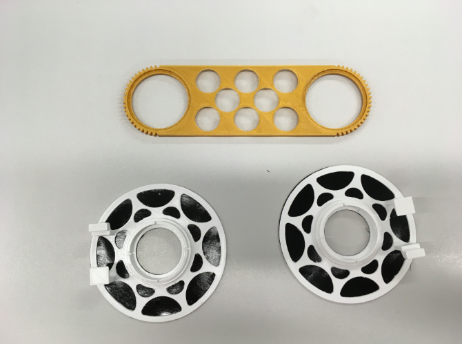
Mounting some components to check design and changing it
Critics: Mounting the servos onto the feet means moving the servos forward and backward by walking as you can see in the video. That was not satisfying, also the wires would have moved all the time and may be interfering with the wires of the air-screws. I decided to move the servos onto the traverse, too.
Changing the design: Mounting the servos onto the traverse together with the pcb includes some changes of design.