Input devices
Week 13
Choossing which device
Electronics and coding are a part of Fab Academy I find particularly difficult considering that I've never done that before, well outside the program. Of course that after the class I was very excited about input devices as I'm always after a class. But something taking to big challenges makes you forget about the processes, documentation and also can generate the delay in the rendering of the week assignments. So, at first, I wanted to use the temperature sensor. I began to reproduce Neil's process. I've been able to make the board but would be a lot to advance for me to program.
My instructor Raphaël Demers helped me a lot this week and showed me a lot about programming. He advises me to simplify what I was going to do, just to make sure I can focus on understanding the ATTiny45 well, all the components that I'll use and the connections I made for the PCB. He also advised me to do the process completely and not only reproduce something. Which was a good advice I think. So, as buttons, sliders and then potentiometer are input devices, I chose to work with those. I had to involve coding and the measurement of something in that assignment so I decided to use the potentiometer that'll interpret voltages to program specific comportment to a LED. So, very simple but to me, it's a great introduction I guess.
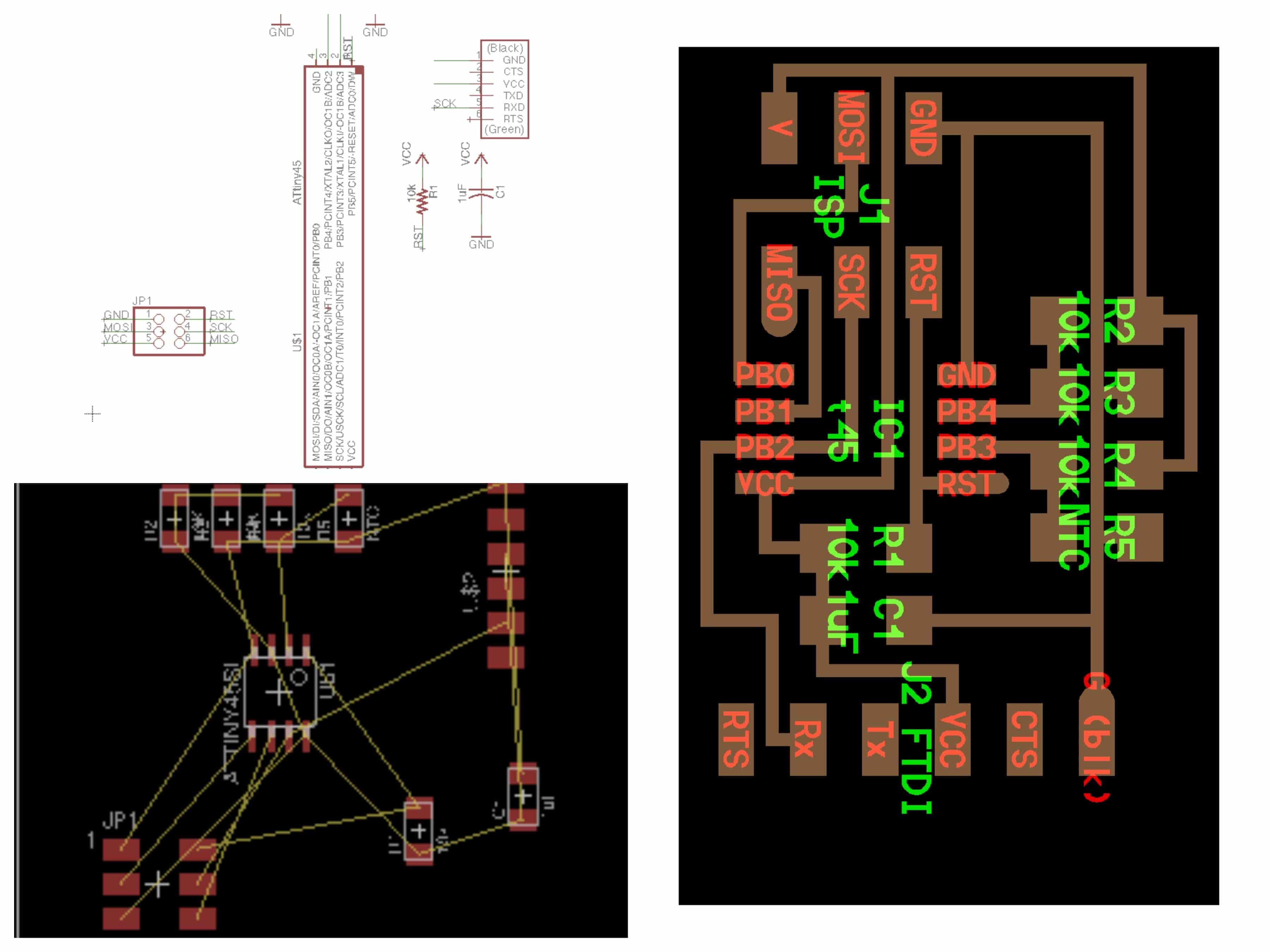
Designing the schematic and the board with Eagle
I have to say that I love Eagle. During Electronics design week, I've been introduced to it and thought it was a very nice tool. I still think so but, I got one problem with it. Well, as long as you use FabAcademy inventory components, I downloaded the Fab library in week6, there's no major problem because you can find every parts really easily. But in that case, the potentiometer I wanted to use wasn't in the Fab inventory, I ordered it on Digikey. So, I tried to find the right parts at first in the standard libraries but didn't find anything. So, I began to look on the web to find additional libraries and I found on Github one specifically made for potentiometer coming from the company that made the one I chose. I downloaded and installed it. When I opened it there was a lot of potentiometer prints but not the one I chose. I looked around the Web a lot never finding anything. So, I had to hack my board a little bit to be able to design the place for it on my PCB. Looking at the components data sheet, I realized then that the space between the 5 branches of my potentiometer and a regular 6 branches header were the same. So, I chose to use this one and use only 5 branches on 6.
In that phase of the assignment, I didn't have any other major problem. I'm not going to take a lot of time for all the steps of making the schematic or the board because they were the same then in Electronics design week. Briefly: 1. Add the components; 2. Connect them together; 3. Go on the board window and place them in the square; 4. Chose the width of the traces using "route" command; 5. design the traces and export in PNG.
I think it's interesting to say that to build my schematic, I use an Arduino schematic. I've never seen one so Raphaël (My instructor) showed me how to read it. Well, the least we can say it that they look pretty nice!
Based on that schematic, I designed mine. But still, it can look easy to understand what that schematic could mean but to me, it seems a bit confusing. So, I had to understand what would become the different connectors in comparison to my ATtiny45. Here are some pictures I looked at:
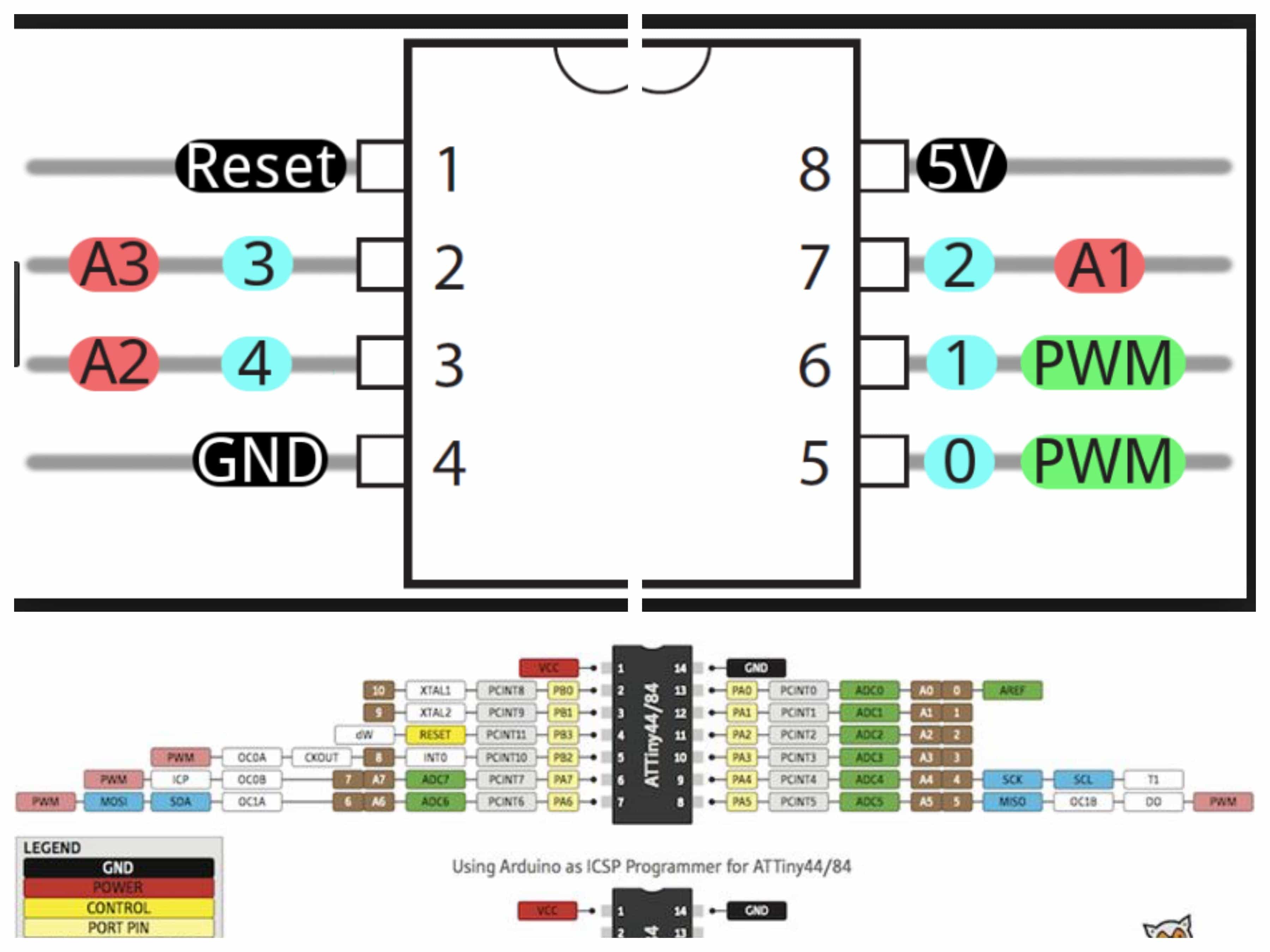
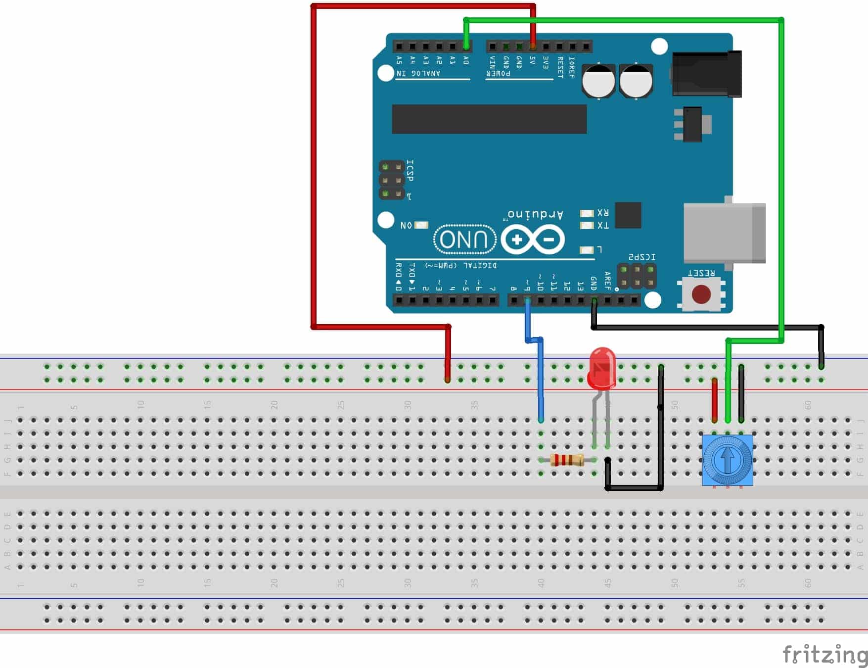
From there, I've been able to design the rest of the board. Fist important thing, I had to make sure that the LED and the potentiometer were on two different analog pins of the ATtiny. I also had to put a resistor connected to the LED so it does not burn. Finally, for the rest of the pins, I followed the logic showed in Neil's temperature sensor design.
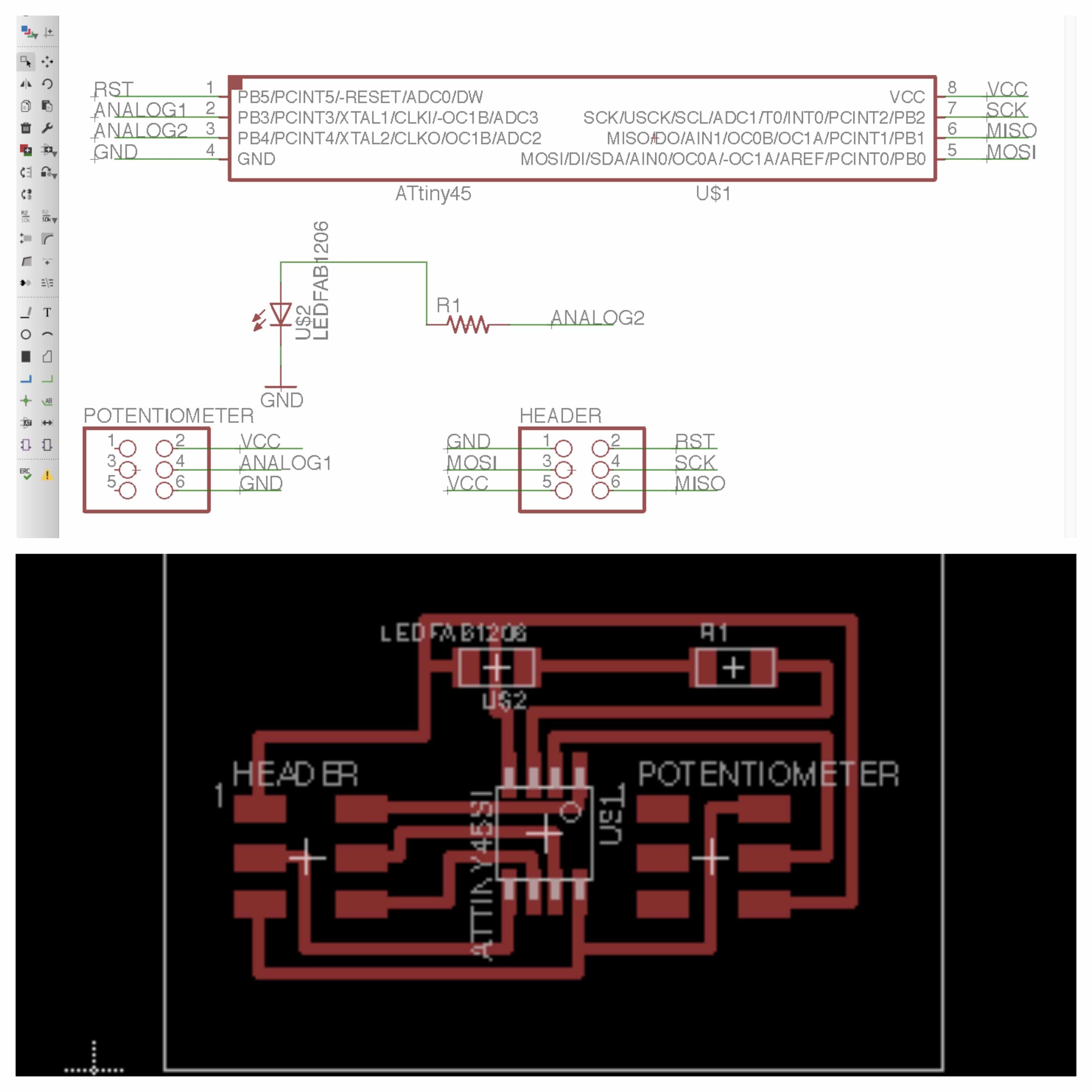
As you may see, the component that I chose as a potentiometer on my schematic and board as 6 pins and looks a lot like a 6pos header. Well, it's because it is! I never found anywhere any libraries that include that specific part. As I already said, I had to look at the component's data sheet to measure the spaces between the branches and find a similar one. The 6 pos header did very well in this case. But, because there's a but, I forgot to measure the size of the component so it's not fitting very well on the board. But it fits!
Connecting all those parts together, even if there's not a lot, was a hard job. It seemed that there's was always an impossible connection in many attempts. So, Raphaël, my instructor, suggested me to based the header and the ATtiny 45 on the board that Neil made for temperature sensor again. Then, I'd put the rest of the parts and there would be fewer connections to design. I worked well.
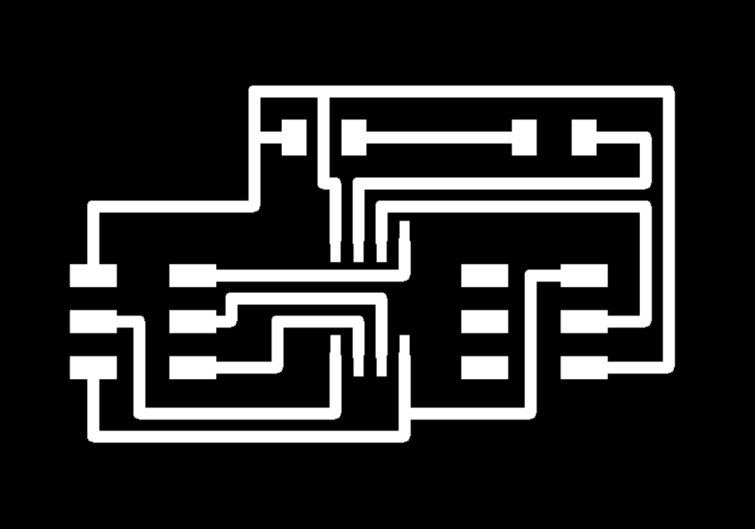
Then, I exported the file in .png to be able to process it in the FabModules.
Milling the PCB
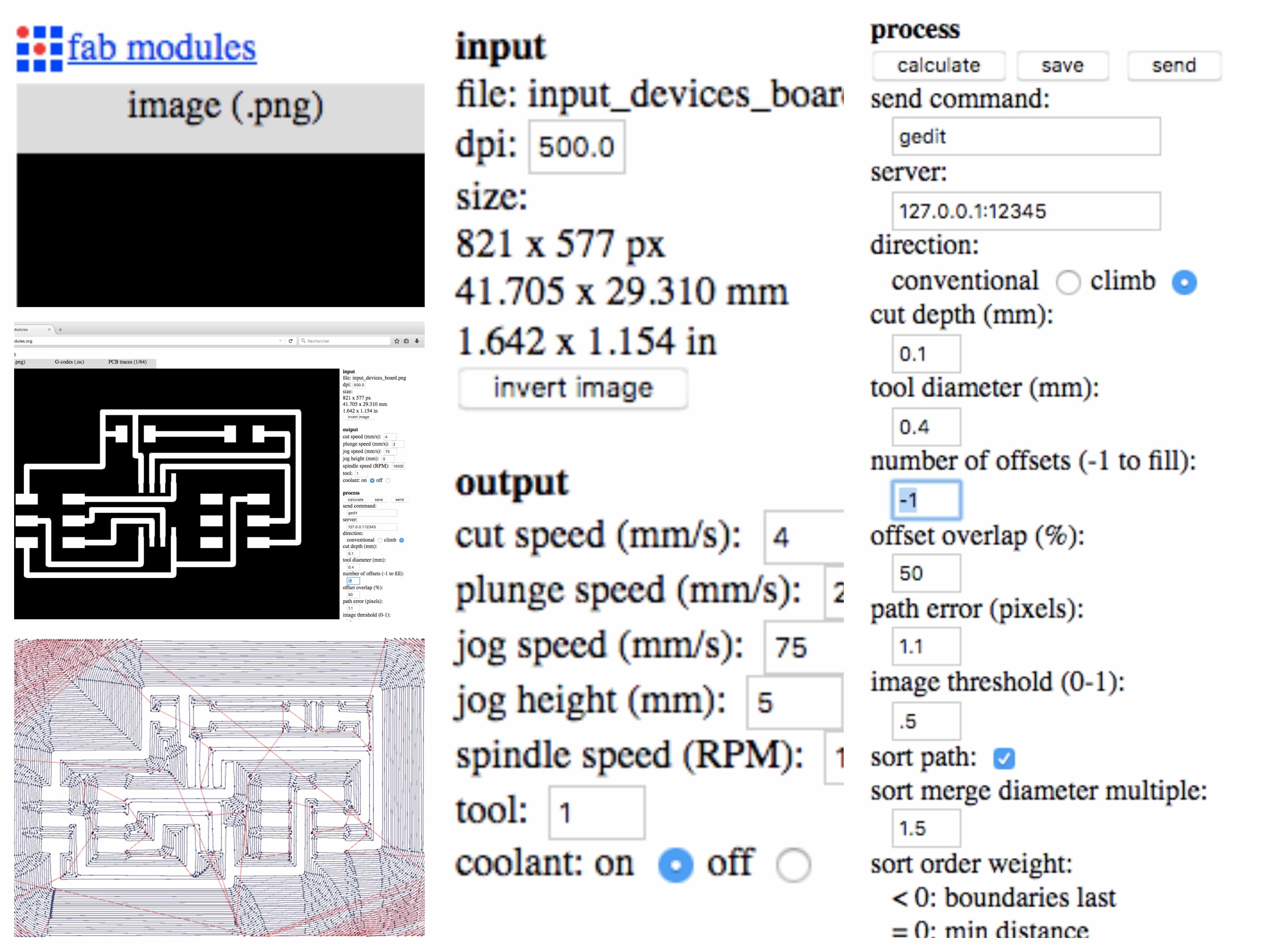
The best new about this week is that I'm getting very good with the milling machine. I understand how it's working and I'm not intimidated by it anymore. Still, even if I'm feeling more comfortable with the machine I think it's still very important to never forget that it's still a dangerous machine. So, never overestimate yourself when using industrial machines. I'm not going to pass a lot of time in the process. If you want more information about it, go to electronics production week. Here the settings I used in the FabModules to mill the PCB. Actually, I used the standard settings, I just put a -1 on number of offsets so it mills the whole thing.
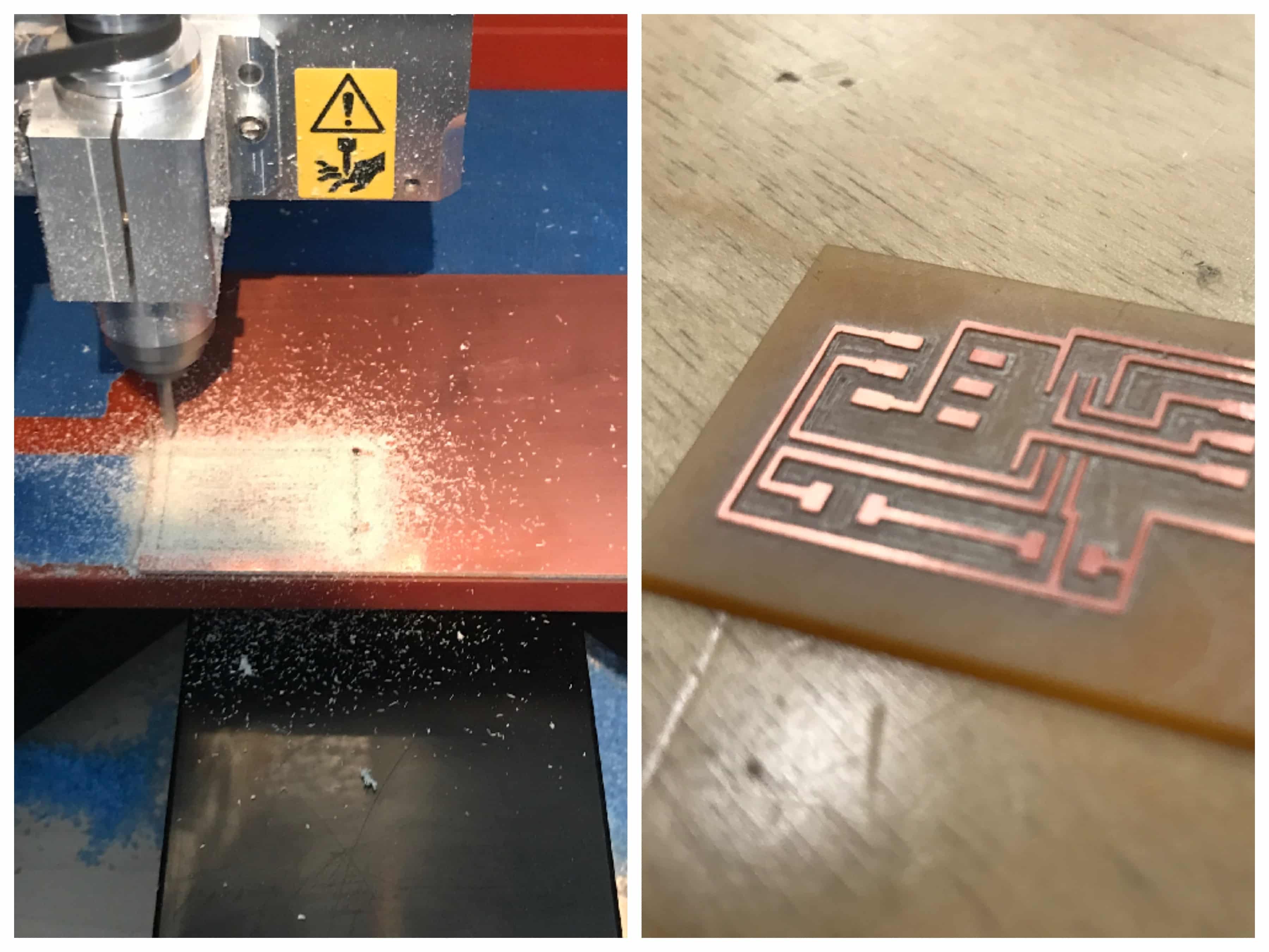
Then, I sent the file to the milling machine. I came out very nice.
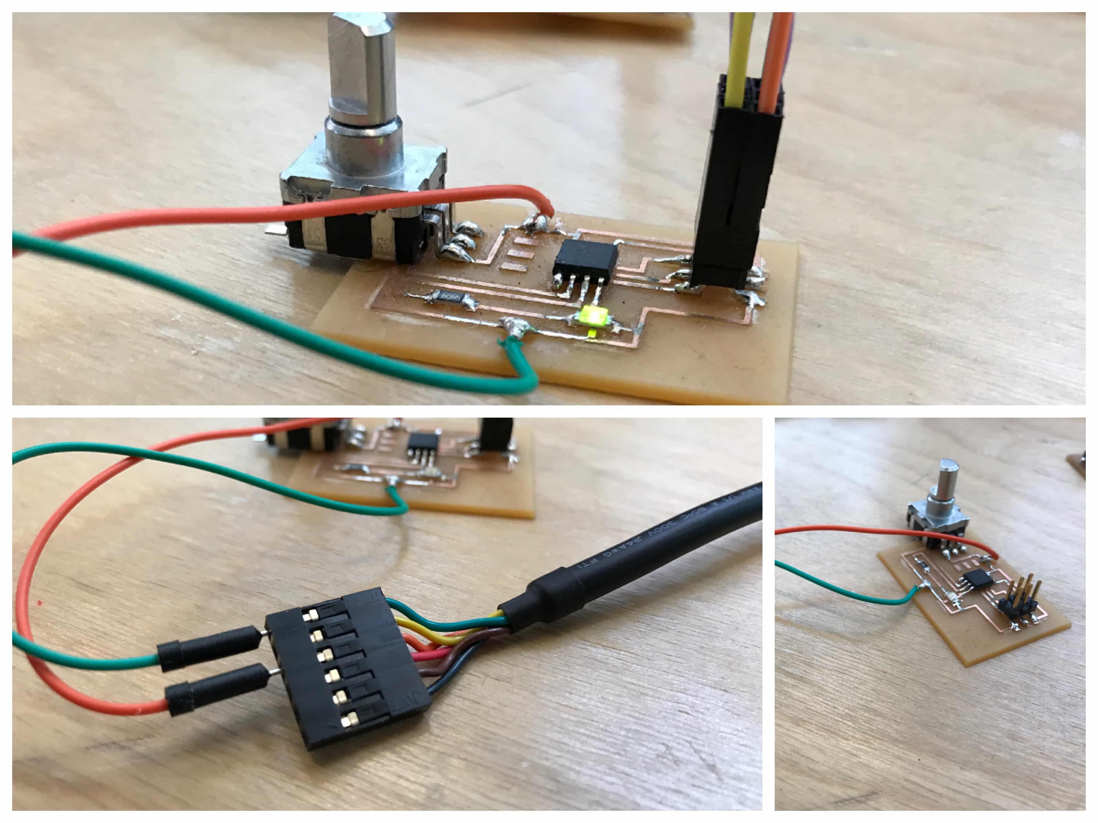
Soldering the parts
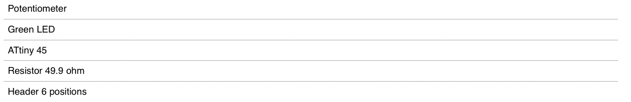
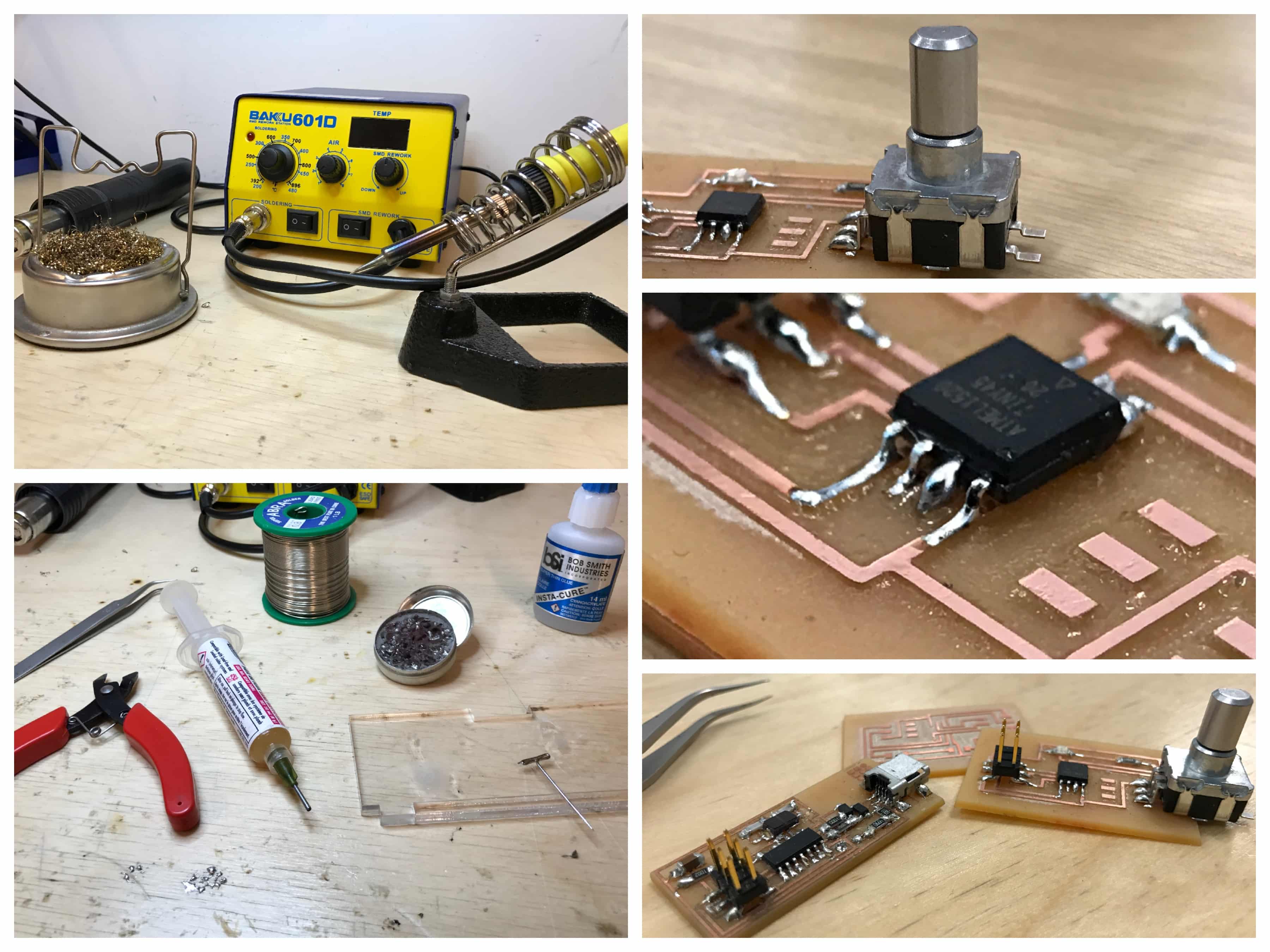
Again, I'm getting better at this ! I even had fun doing it and thought that it would have been nice to have more pieces to sold ! Here's the parts I needed to solder and some close picture of them.
Programing the board
To me, this is the most alien part of the whole process. This is why at first I've been advice to not take a to the complex project. Here, the code is really basic but helped me understand some specific function of Arduino language. By the way, Arduino's reference page is really awesome! First, about the structure with setup and loop. Then, analog read, delay, and mapping. The assignment was to measure something so, here the potentiometer measure the voltage and translate it in a specific pattern with the LED. Pretty simple you'll say .. well, to me it is really nice. Moreover, I'll be able to use it for my final project!
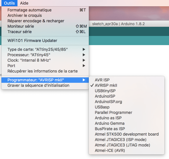
The first step for me was to add the ATtiny45 to the available programmer within the Arduino software. To do that, I used the tutorial High-Low tech. The tutorial is very well made and everything went well. So now I can chose the ATtiny45 as a programmer.
The next step was to create the code. My instructor Raphaël followed me through that process the code is pretty simple again but I learned a lot from it. Then, I compiled it to make sure that there was no error in it.
/*
Turns on an LED on for one second, then off for one second, repeatedly.

Most Arduinos have an on-board LED you can control. On the UNO, MEGA and ZERO
it is attached to digital pin 13, on MKR1000 on pin 6. LED_BUILTIN is set to
the correct LED pin independent of which board is used.
If you want to know what pin the on-board LED is connected to on your Arduino model,
check the Technical Specs of your board  at https://www.arduino.cc/en/Main/Products
This example code is in the public domain.

modified 8 May 2014
by Scott Fitzgerald

modified 2 Sep 2016
by Arturo Guadalupi

modified 8 Sep 2016
by Colby Newman

modified 8 juillet 2017
by Mathieu Laporte
*/
void setup() {
// put your setup code here, to run once:
pinMode(9, OUTPUT); //Set LED pin as output
pinMode(A0, INPUT); //Set Potentiometer pin as input
}

void loop() {
// put your main code here, to run repeatedly:
digitalWrite(4, HIGH); //Turn the LED on
delay(1000); //Time the LED stays on
digitalWrite(4, LOW); //Turn the LED off
//delay(500); //Time the LED stays off

int potValue=analogRead(A3); //read potentiometer value and store it in potValue
int dTime=map(potValue,0,1023,1000,5000); //map pot reading to milliseconds for the delay
delay(dTime); //Set the dTime mapping as the delay variable
}
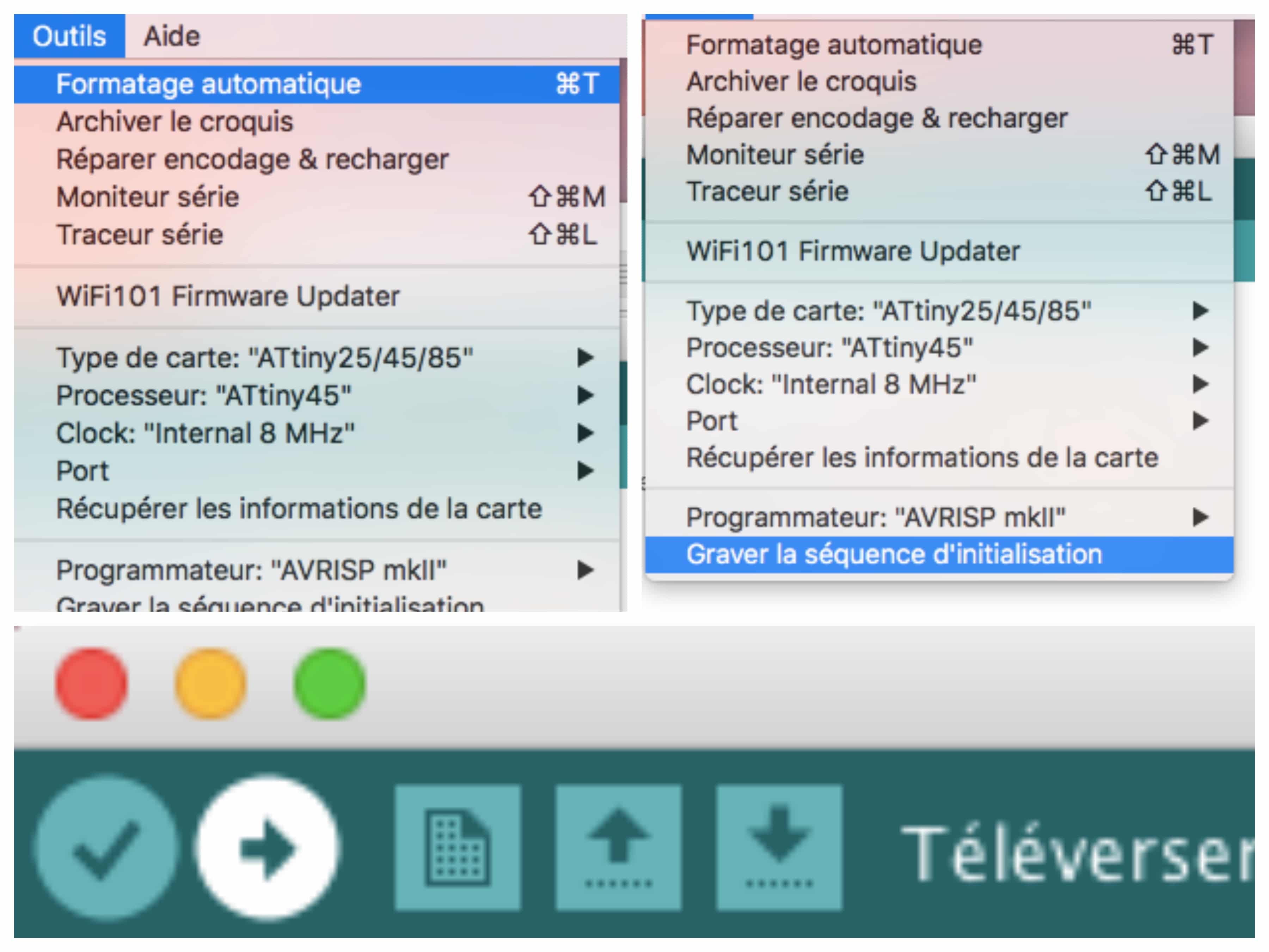
Finally, the last step is to put the code into the board. The two pre-steps : 1. Formatage automatique (Which is optional if I remember well ...); 2. Graver la séquence d'initialisation. After that you can upload it into your programmer !
Final result