Output devices
Week 10
What to choose as an output device!
Well, that question was easy to answer. As my final project is getting clearer in my head, I know now that I'll need a dc motor to make my structure moving, I'll need two in fact. So, it is a good opportunity for me to test some PCB design and coding too. I thought also that I could go a bit further and already look at the input devices week and add a potentiometer to it. I'd make two goals in one shot. That sounds great to me. Overall, it seemed easier that I thought at first. I begin to love Eagle and PCB designing, we've been practicing to do that for a while already and it starts to get in. So, I'm not going to talk deeply about things I've already document the past weeks but concentrate on new things and overall making.
Making an arduino test
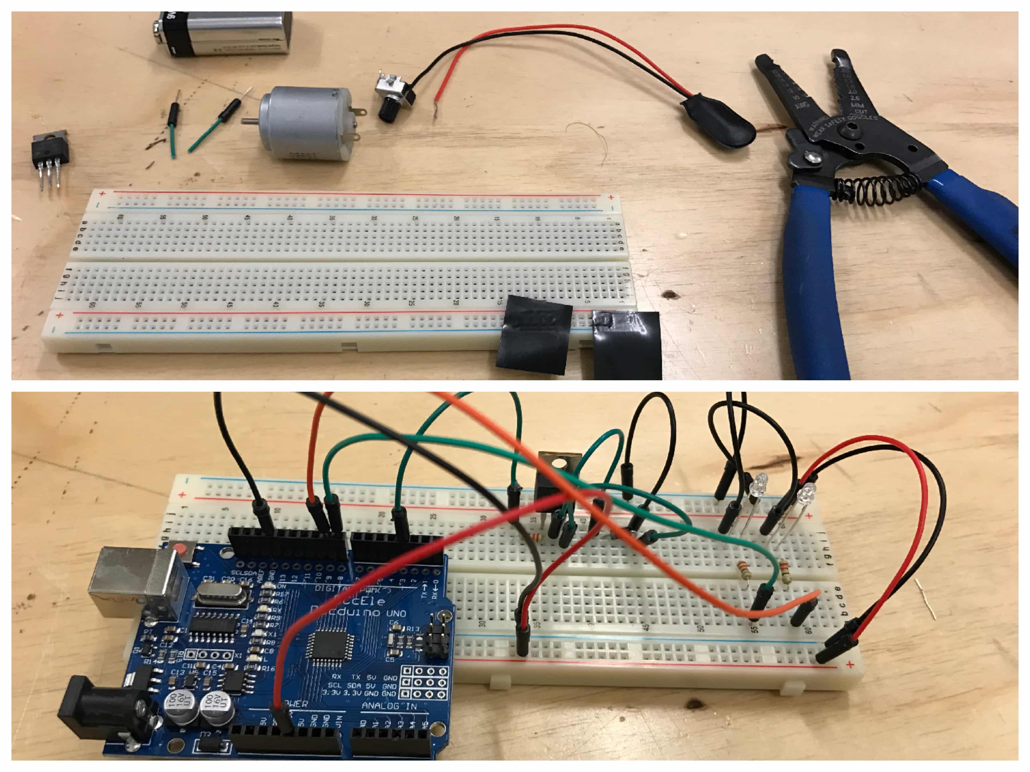
The first step of my process was to look at some already made circuits, I always do that because it's hard to start from nothing at that point of my learning process. Then, because I chose to learn the Arduino language, I thought I'd begin by basing myself on Arduino schematic, that are by the way really beautiful to look at. I thought that after this, I'd understand the flow better and I'd able to transfer it with and ATTiny and design the whole board. Here are what I based myself on and some photos of that exploration phase.

Designing and making the PCB
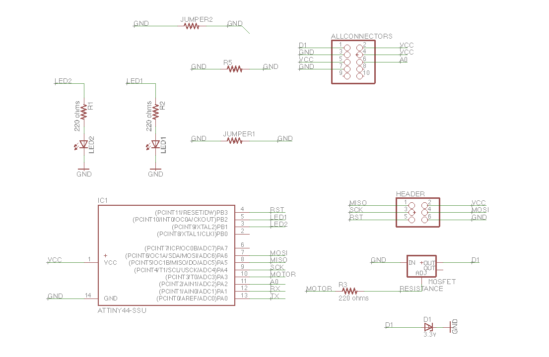
The second part was to make it independent from the Arduino Uno and make it on a real copper PCB. As in the electronics design week, I started by finding all the component I needed in the libraries and prepare to name the connections to connect everything together. I had this first Arduino attempts to base myself on. I found all the components easily and then prepared the schematics.
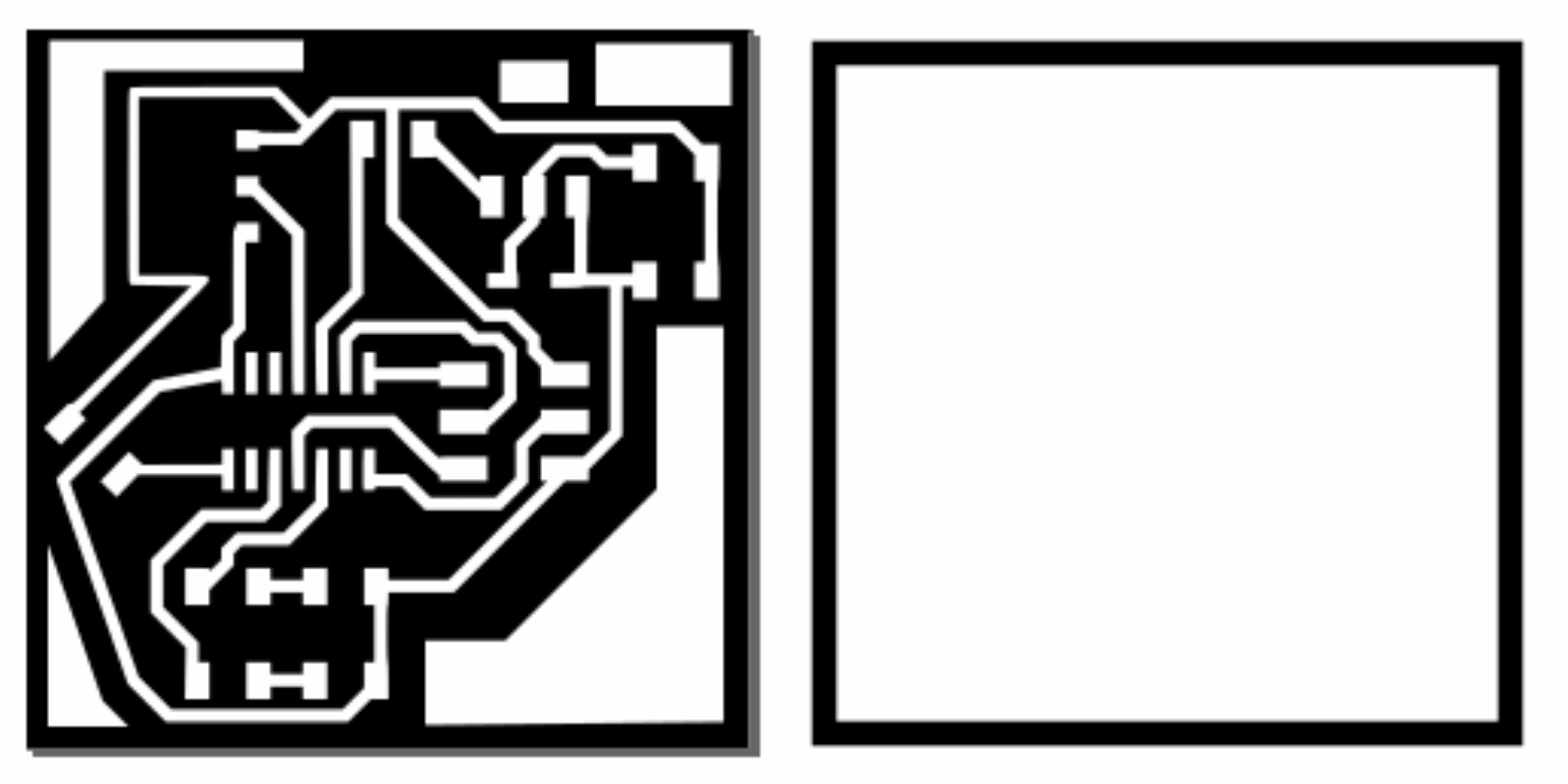
I then went to the board section and began to place all the prints. I tried to make it work lots of time without adding any jumpers, but it never worked. I got frustrated. Then, I discovered the Autorouter option but this options couldn't find any 100% path. I really needed to add some jumpers I guessed. So, I took the highest possible path and then I added some jumpers and connected them myself. Here's some key steps and the final result.


The next steps are used to prepare that board so it can be mill and then mill it :
There you go, you have a superbe board !!!

Solder the components
Well, there's not a lot to tell about that phase ... I soldered the components on the board. Here's video of it. I have to say that I'm getting better at it !
Programming the ATTiny
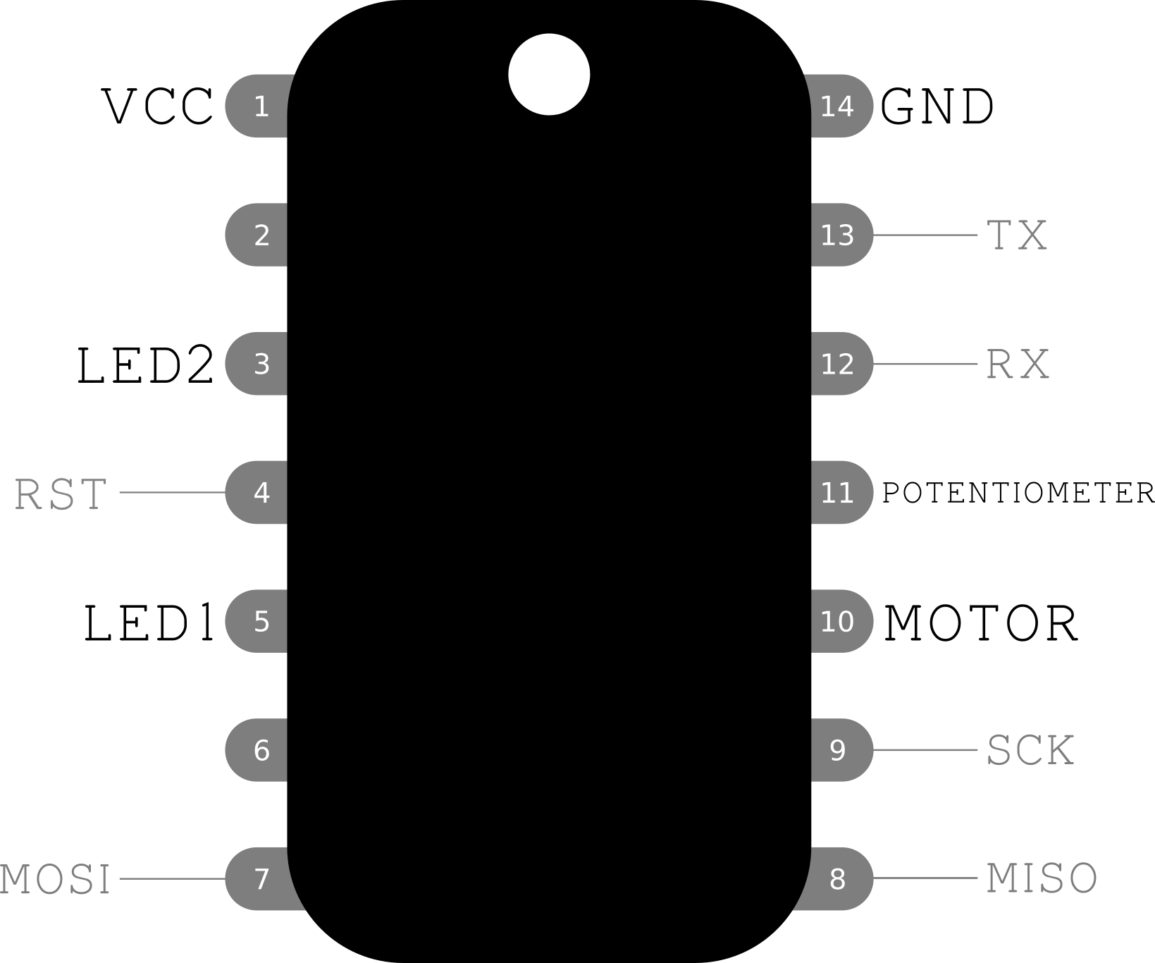
This was my biggest fear. I got it right. I had to look at some different codes to inspire me and understand what it was all about. Again, the sheet that shows the different names of pins between Arduino Uno and ATTiny44 was very useful. After finding the right pins, I pushed the code in, as I showed in Embedded programming week and it came alive!

Here's the code I pushed in the chip using the FabISP in the same way then in Embedded programming week. Everything went well here too !
int analogInPin = 11;
int sensorValue = 0;
int outputValue = 0;
int transistorPin = 10;
void setup()
{
pinMode(3, OUTPUT);
pinMode(5, OUTPUT);
pinMode(transistorPin, OUTPUT);
}
void loop()
{
sensorValue = analogRead(analogInPin);
outputValue = map(sensorValue, 0, 1023, 0, 255);
analogWrite(transistorPin,outputValue);
if (outputValue >= 160)
{
//example
digitalWrite(8, HIGH);
digitalWrite(9, LOW);
}
else
{ digitalWrite(9, HIGH);
digitalWrite(8, LOW);
}
delay(10);
}
Final result
I now time to show the final result !!! Yay !