Final project
Process
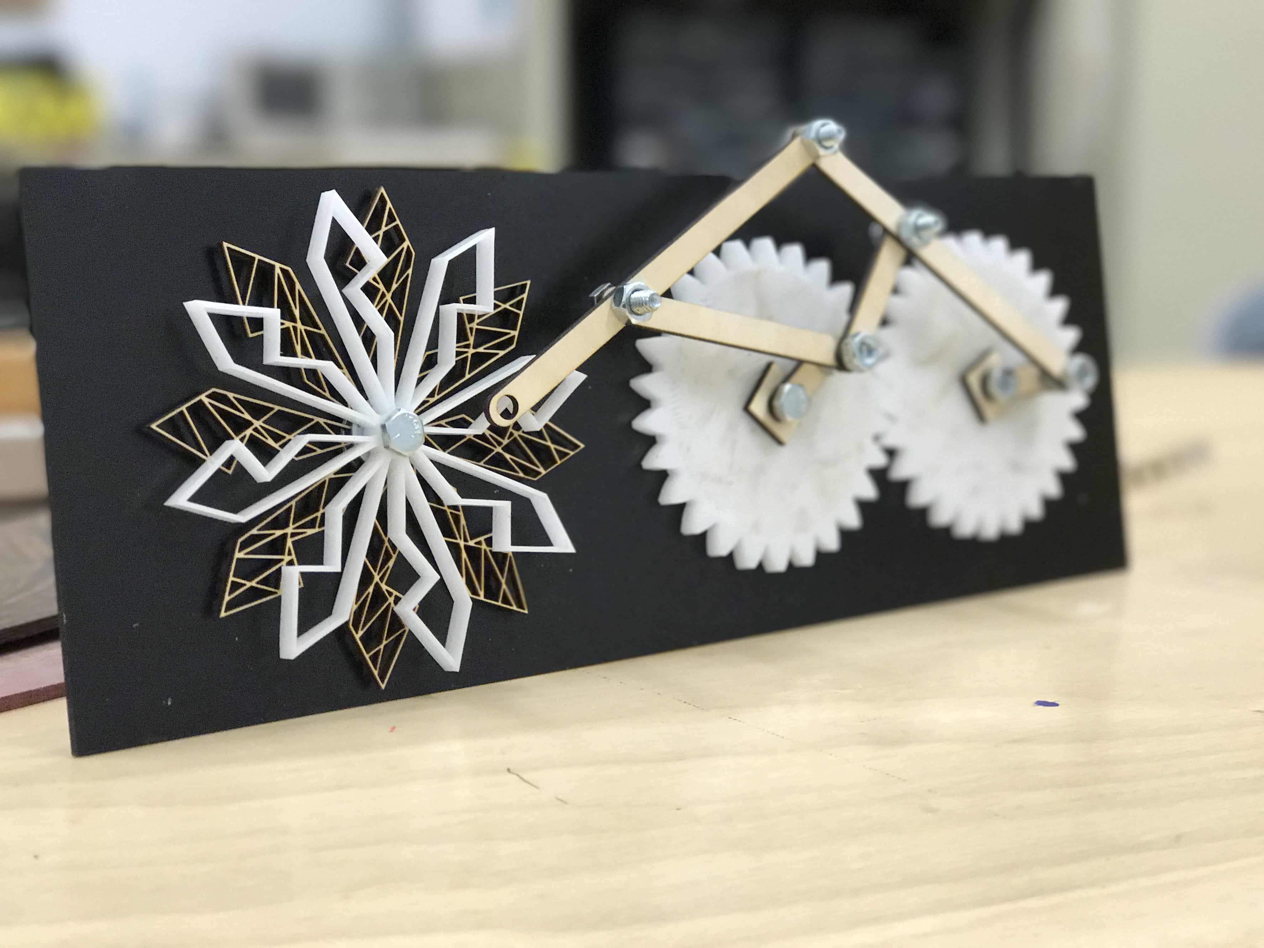
Where our we now !?!
Well, after conceptualizing the whole thing with a sketch and also a first small iteration of the project, having plans all the material I'll need and prepare a match's plan, I think I'm ready to begin to design the part, the systems, and the circuits. Here a little remembering of where we were in picture and I'll begin to explain how I built the machine.
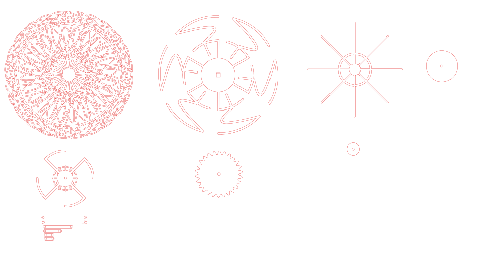
Designing the laser cut parts
To me, the first step was to design and laser cut all the parts that needed to be cut because I'd have a concrete base to continue building. It was possible because I already had the screws that I wanted to use so I could also plan their integration. All the plans are availlable with the download button.
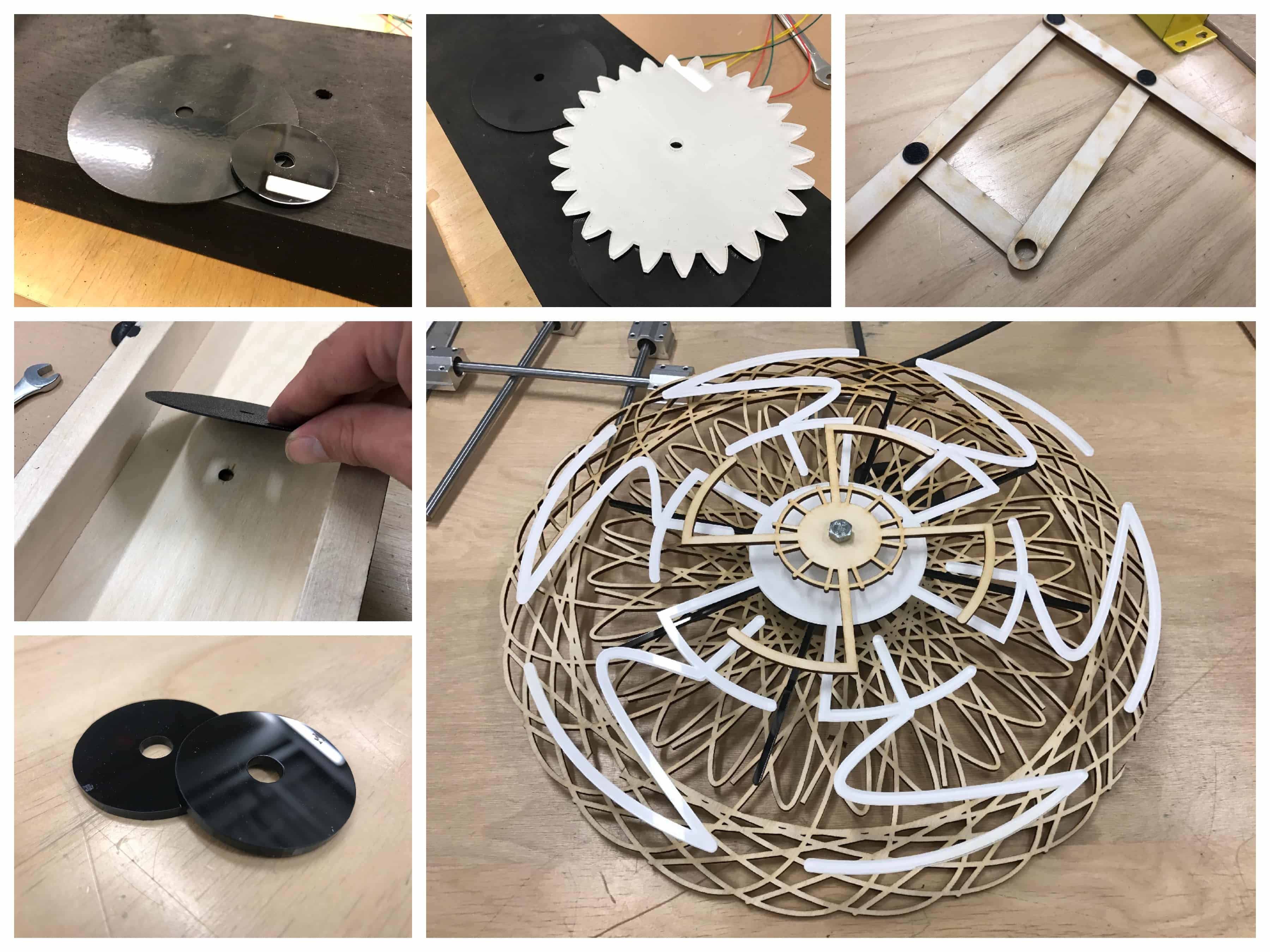
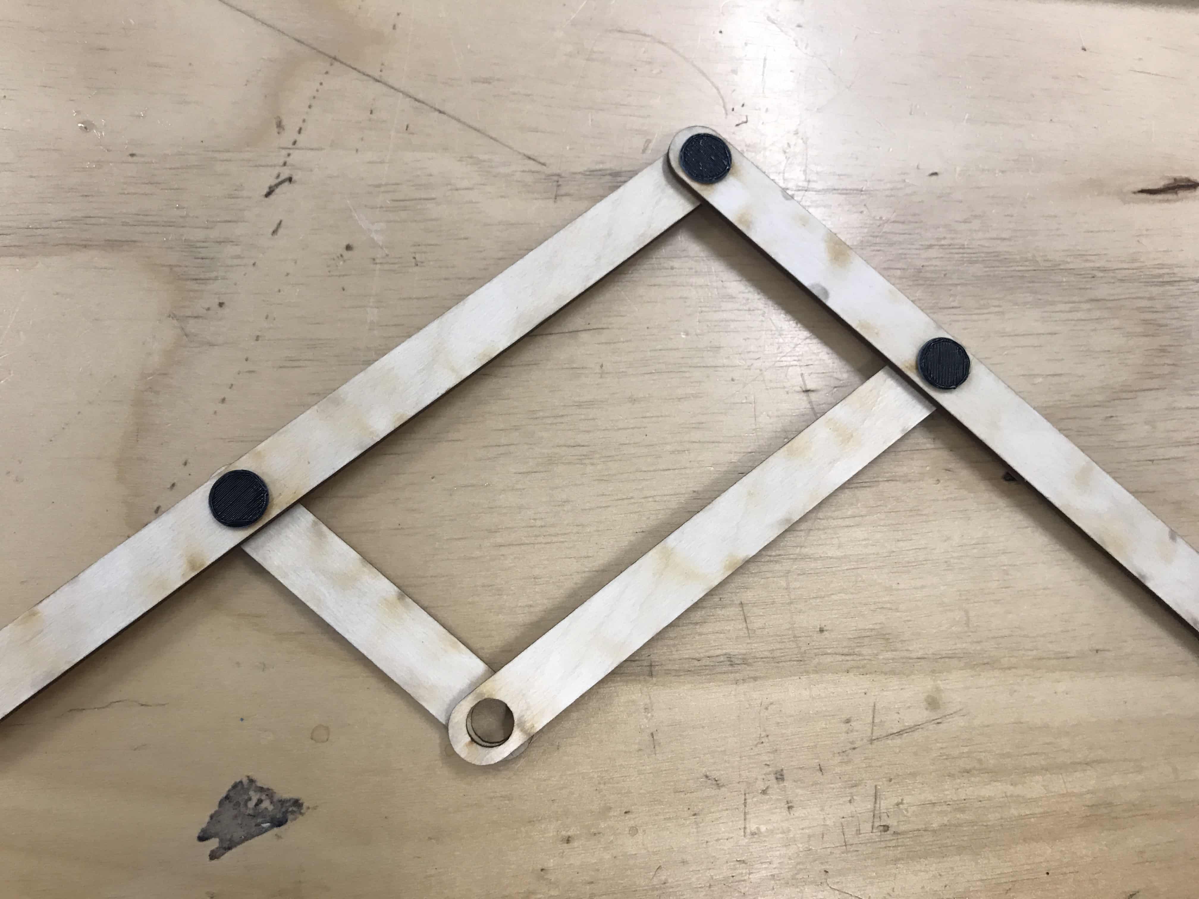
Assemble laser cut parts
After cutting them, I had to put them together. For the rotarty part of it, the main challenge was to make a process that'll allow to parts to go in different direction. Here's a sketch of now it is made (Clic on the picture to zoom):
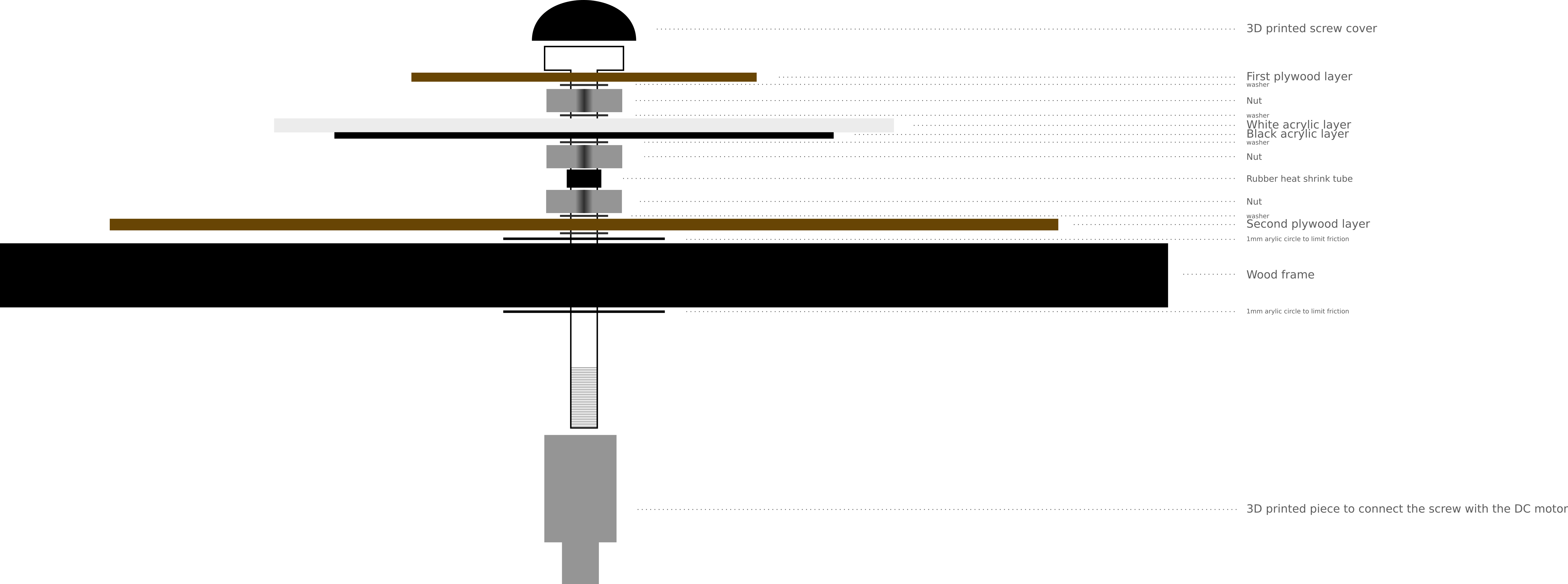 I was trying to find a way to explain this whole process and I thought that "une image vaut mille mots" as we say in french (A photo worth thousand words). I think this sketch represent very well the way it is assembled.
Designing the 3D printed parts
As you can see in the sketch, there are two pieces that are 3D printed and I needed to design them. Each of them come from a need that came out and that I needed to resolve. So, I decided to open Fusion360 and design them and it worked very well! I was amazed by this new capacity I develop through this program to pass from a problematic to a concrete solution in so little time. There's three pieces I made :
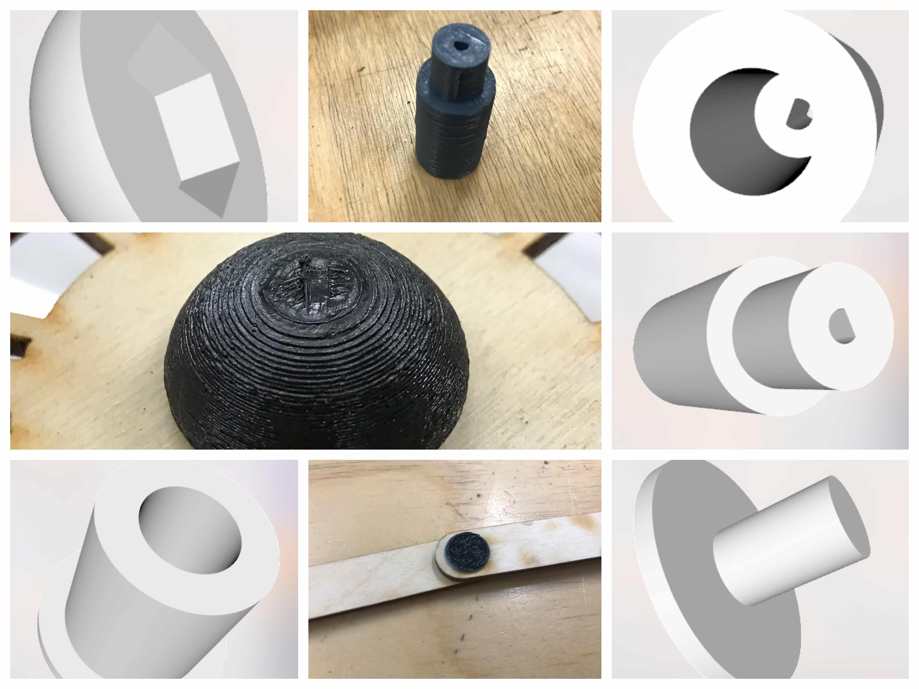 The two first parts are assembled within the rotary piece and are displayed in the sketch. For the connectors, well I put them in the wholes of the pantograph and glued them with rubber glue. I choose rubber glue because it stretches a little bit. Epoxy and crazy glues are too stiff they break but the rubber contact glue gives just the right about of flexibility.
Prepare the frame
Now that I have all the pieces that I need, I thought it was the perfect time to prepare the frame to welcome the pieces. I had to plan the place for the rotary piece, the two gears and the two potentiometers and them, finish it with a nice black mat paint.
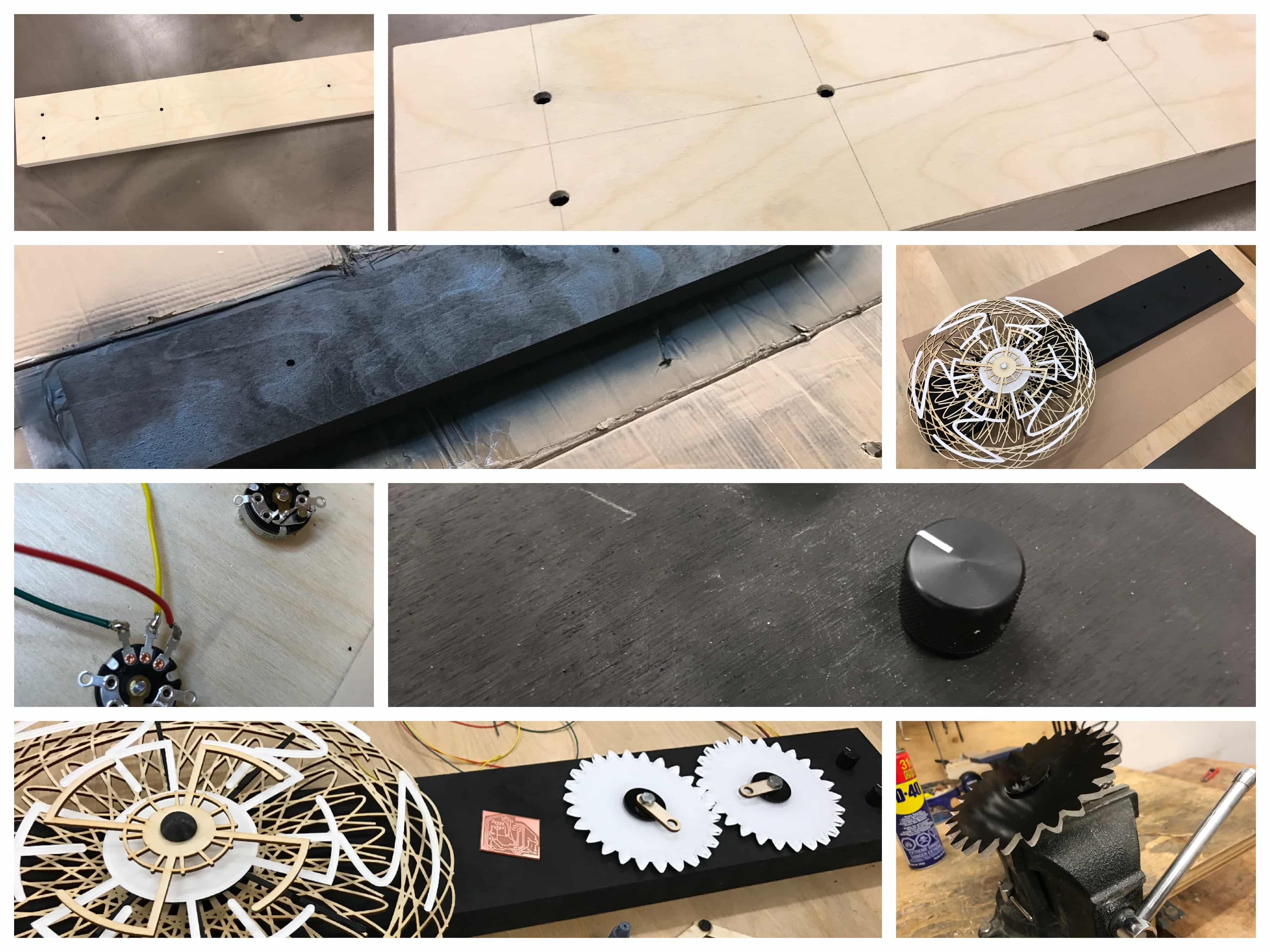
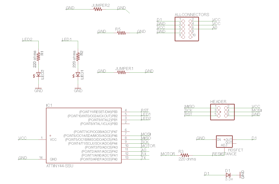
Desiging and producing the electronics
This is almost the last part. In this specific case, it wasn't too difficult because I made the all the design and the production during output and input devices. I integrated them in two boards for the two potentiometers.
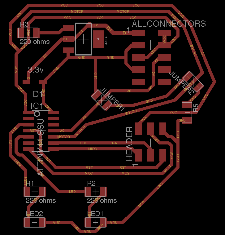
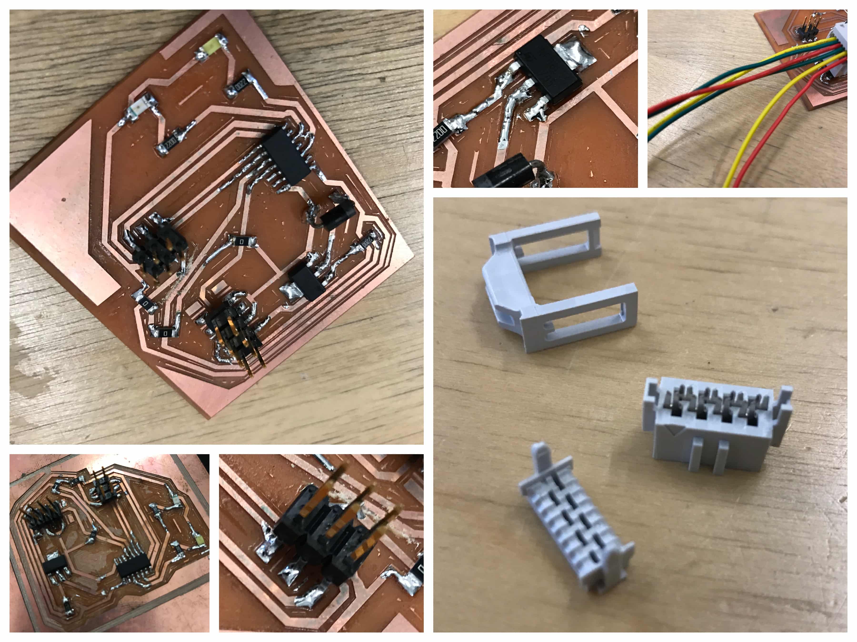
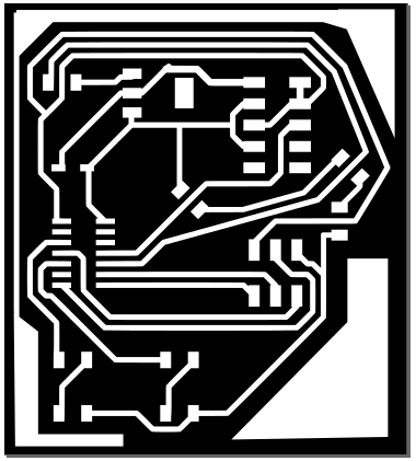 So, I'm not going back in details for all this phases. The challenge here was to well integrate them but with that frame, it wasn't to hard to put everything in the back. I also used this little 8 positions socket and a 8 positions header to make all the connections to the potentiometers, DC motors and power supply even cleaner. Here also some pictures of the result :
The code
In this project, the code is a mix of the codes I used for input and output weeks. The code is pretty simple but does the job ! Here it is :
int analogInPin = 11;
int sensorValue = 0;
int outputValue = 0;
int transistorPin = 10;
void setup()
{
pinMode(3, OUTPUT);
pinMode(5, OUTPUT);
pinMode(transistorPin, OUTPUT);
}
void loop()
{
sensorValue = analogRead(analogInPin)/20;
outputValue = map(sensorValue, 0, 1023, 0, 255);
analogWrite(transistorPin, sensorValue);
if (sensorValue >= 160)
{
digitalWrite(8, HIGH);
digitalWrite(9, LOW);
}
else
{ digitalWrite(9, HIGH);
digitalWrite(8, LOW);
}
}
Final steps
Now, it's time to finish everything ! I still have some small problems to resolve, we are monday the 26th and I have to finish for wenesday and I hope I'll be able to it. Everything is done, but I broke one branch of my panthograph and also burned one the the two circuit :( Nothing I an redo but couln't have that final shoot of it !! Here it is in picture though.
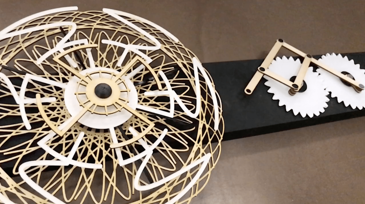 But good new ! I can manke one of them work and show you the shape it creates and the two side rotary piece which was the most important overall. Also, the motor 12v doesn't have enough grip to make turn in a constant rythme. I'll have to to buy a geared head motor that I'll integrate as soon as possible.