Week 5
3D scanning and
printing
Assignment
- Test the design rules for your printer(s) (group project)
- Design and 3D print an object (small, few cm) that could not be made subtractively
- 3D scan an object (and optionally print it) (extra credit: make your own scanner)
Week workflow
Here is how I see the week's flow :
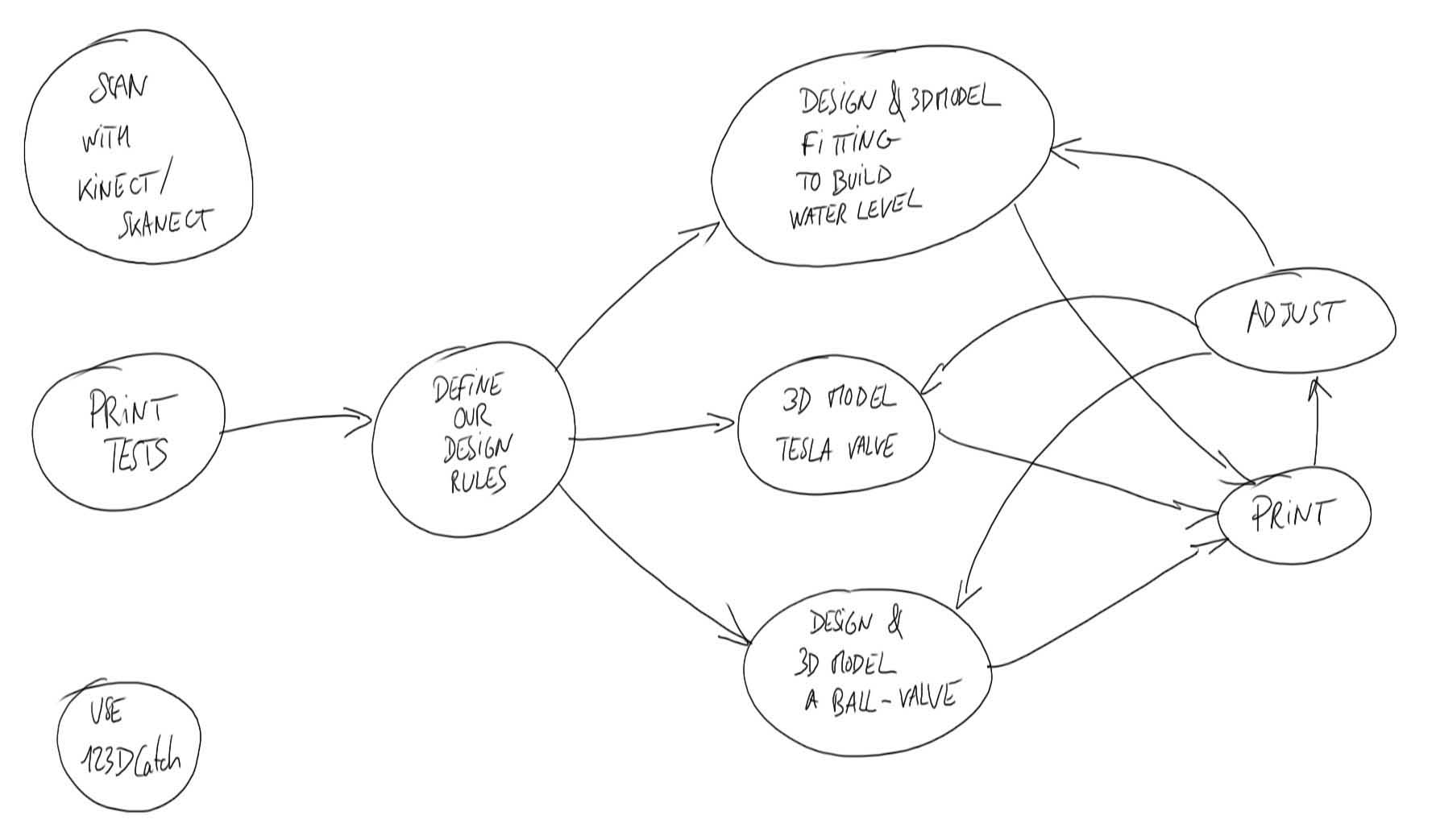
Flow chart for this week
Table of content :
- Define Design Rules
- Design and print of a plumbing part
- Printing a tesla valve
- Design and print of a fluidic diode
- Generating gcode with Grasshopper
- 3D scan with Kinect
- 3D scan with 123D Catch
- Source Files
STEPS
Defining Design Rules
I started to look for a test 3D model to try our Ultimaker 2 here at the GreenFabLab.
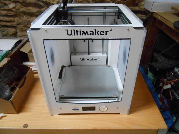
Our Ultimaker 2 3D printer
Understanding the challenges of 3d printing (overhang, bridges, tolerances) I picked this one on Thingiverse:
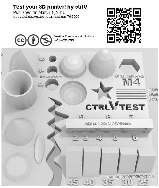
3D test model
We'll be able to try many different challenges that occur during 3D printing.
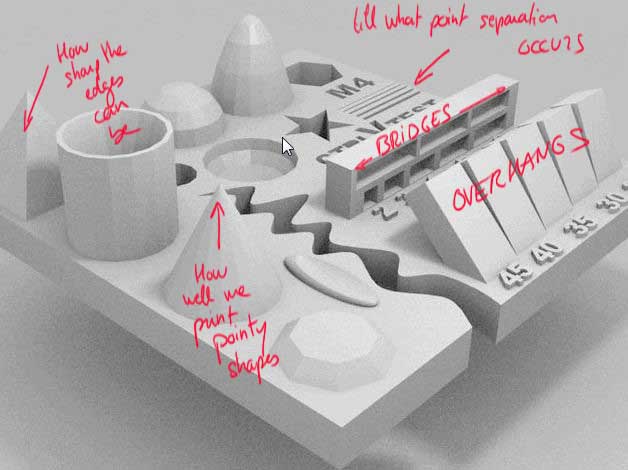
Challenges we can test
But first we need to be able to transform our model in something that the ultimaker can read.
We call this g-code. This is a set of basic instructions, like "move from here to there at this speed".
So the next step is to download a software that can generate a gcode from a model, usually in STL format.
These softwares are called "slicing software" because they split the model height-wise in many layers that will later be printed one by one.
We'll use Cura :

Cura Software
After we've installed Cura, gone through the doc and updated our Ultimaker's firmware, we load our test model and here it is in Cura, all sliced :
Our model in cura
A nice feature to make the model stick to the heated plate of the 3D printer is the "Brim" feature.
It basically builds a very thin layer of the material we use (here PLA) around the base of the model that's easy to break off after the print is done.
There is many other parameters we can play with in expert/advanced mode such as the thickness of specific layers, the speed, how the model is attached onto the printer plate (brim), if it needs support underneath, etc.
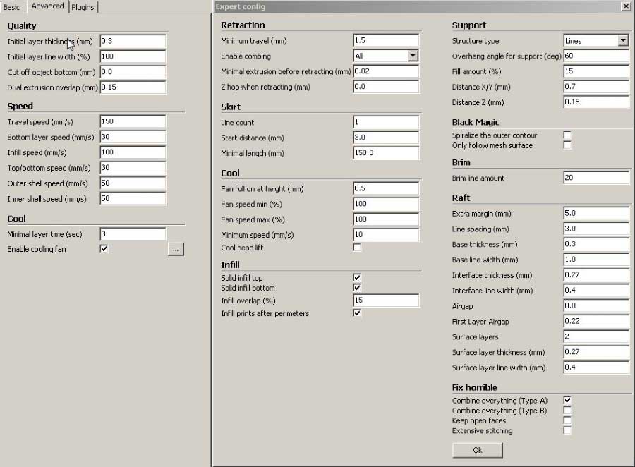
Parameters in cura
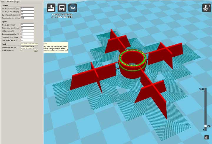
But for a start, to print our test model, we'll just use the normal print from the basic mode :
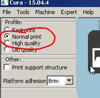
Normal print in Cura
So we generate the gcode and save it to the SD card that the Ultimaker 2 reads.
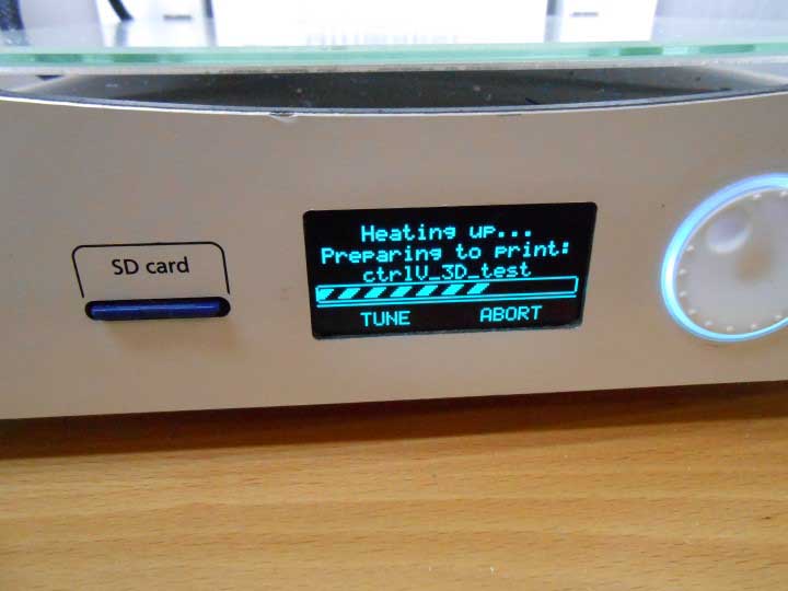
Right before printing the machine (nozzle) heats up :
Heating up the nozzle
Till melted plastic exits the nozzle smoothly :
Heating up and starting the brim
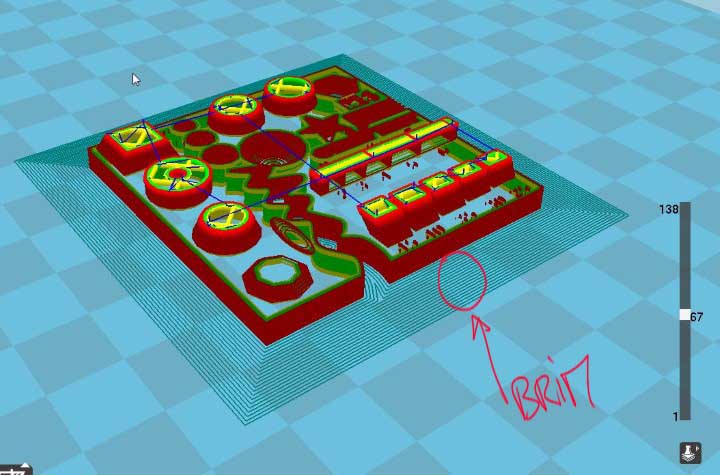
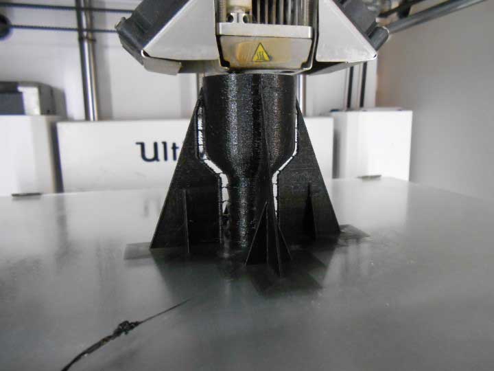
When our print starts, I notice that the Brim is not working properly.
Every tracks should stick to each other, which is not the case :
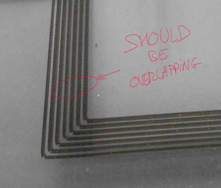
traces not touching during the Brim process
To correct this I do two things : I make sure our plate is level and at the right "zero height". The Ultimaker has a nice tutorial to get it leveled. I followed the instructions indicated.
I also correct the buildplate temperature. It was at 40 °C. I put it at 60 °C :
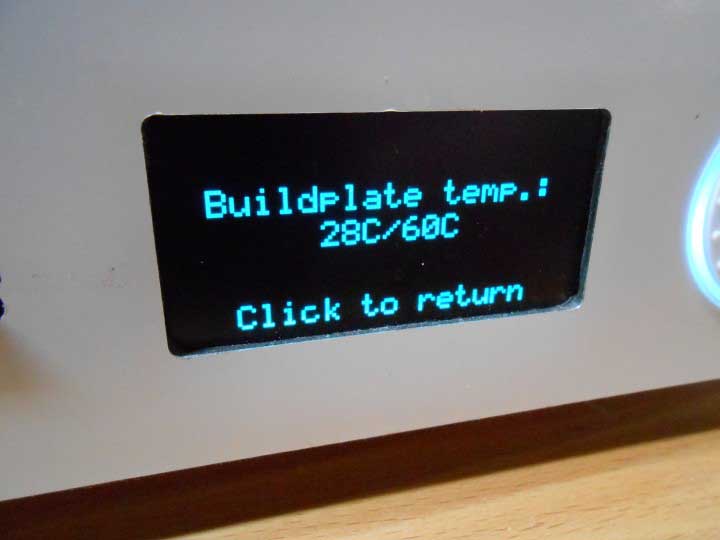
traces not touching during the Brim process
Okay, second try :
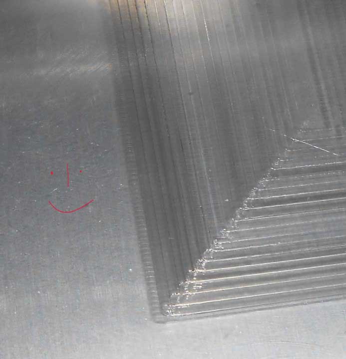
Traces touching during the Brim
Good, the brim is one single thin and continuous layer.
We contemplate our first test being printed :
Our test model being printed
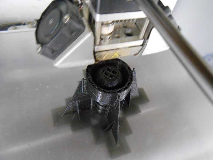
Here it is finished :
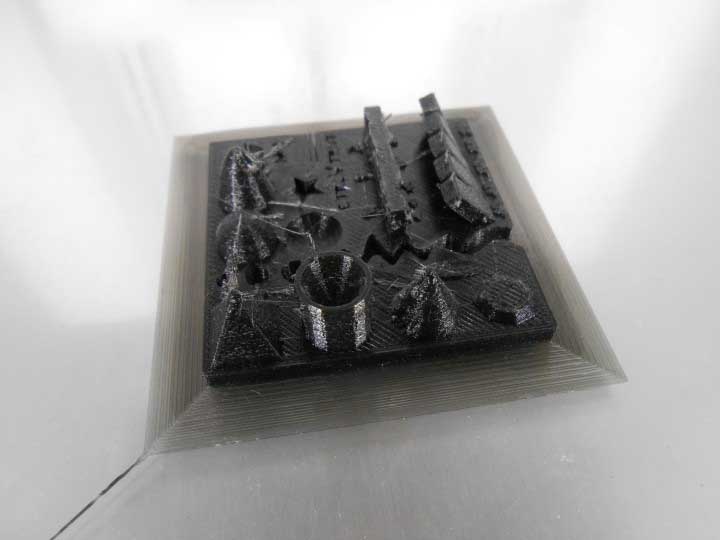
The printed test model
Alright, so what's working and what's not ?
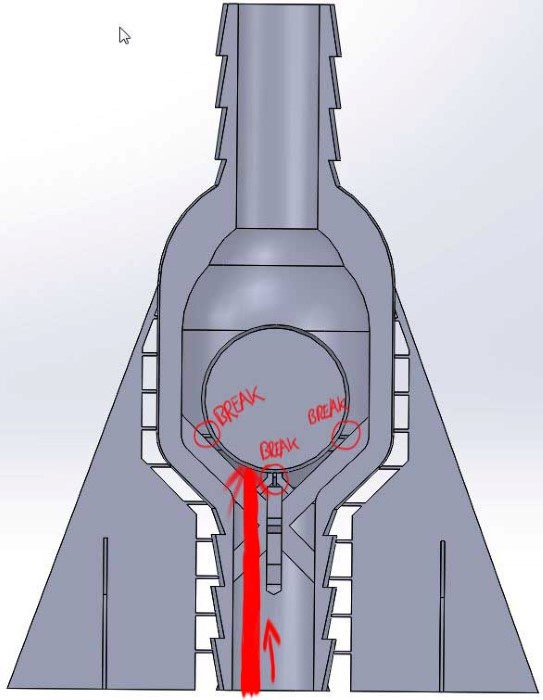
Wrong :
Using a caliper I notice a shy .5mm difference between the measurements in the CAD software and reality. So I'll have to take this in consideration for future designs.
It shows with the gaps in the model : Only two are actual gaps in reality.
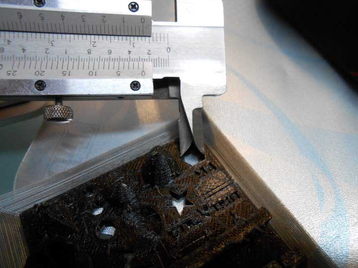
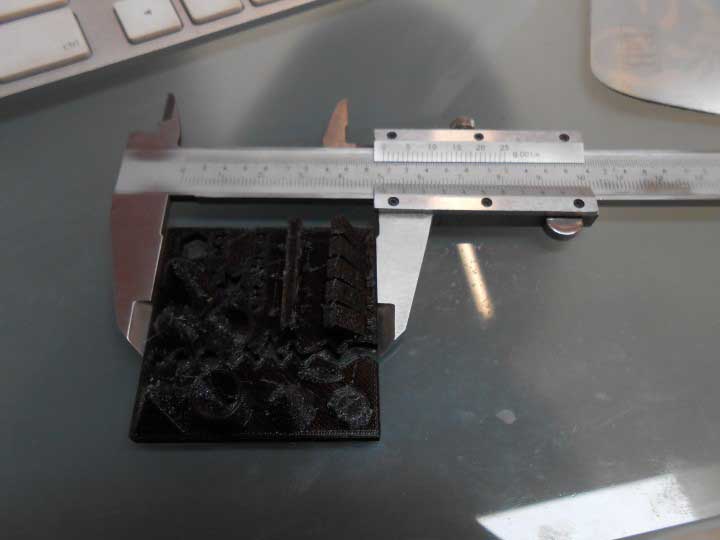
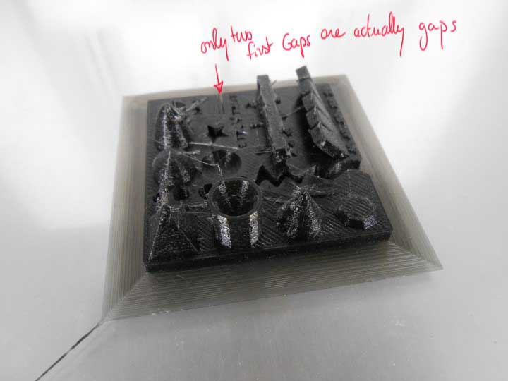
The differences between CAD and reality
What's right?
Well, the overhangs are pretty good, up to 45°.
The bridges also (horizontal connections) :
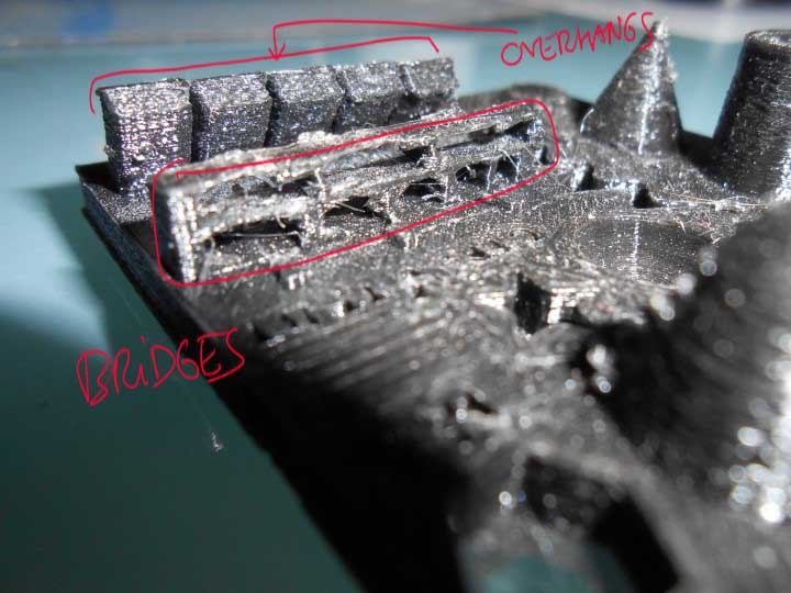
Overhangs and Bridges OK
So to conclude on the experimenting, the design rules are defined as follows :
- Take into consideration the 0.25 size positive offset there is between a shell in CAD and in reality
- Avoid the bridges as much as possible
- Find the best orientation for the object to grow thinking about the overhangs
- Same as before thinking about stability and supports
So... we all this in mind, let's model something !
Design and print a plumbing part
One thing that's very handy on construction sites is a long distance level.
Let's make a part that can easily turn two plastic bottles into a water level. Cause water sits flat right?
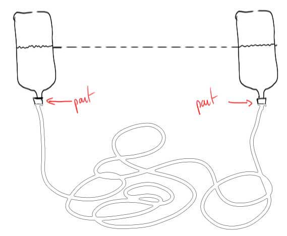
Water level
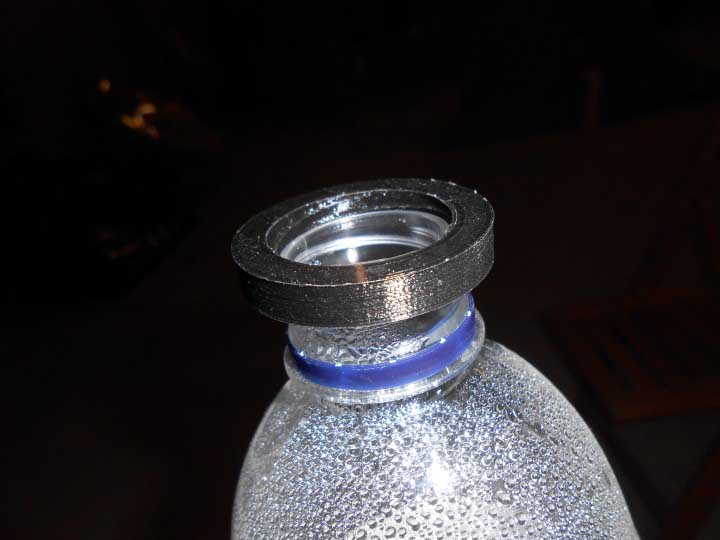
To help me, I cut in half a cap and reverse engineered it !
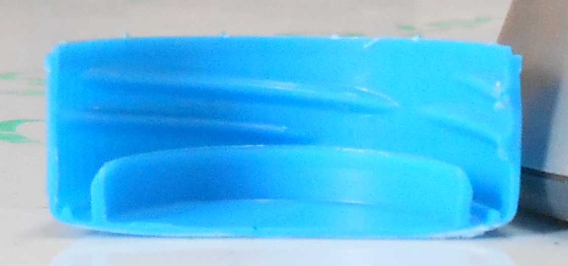
How a cap is
This is a part that cannot be manufactured substractively.
It's going to be difficult to achieve the water tightness as it is done with the cap material because PLA is harder but I'll try.
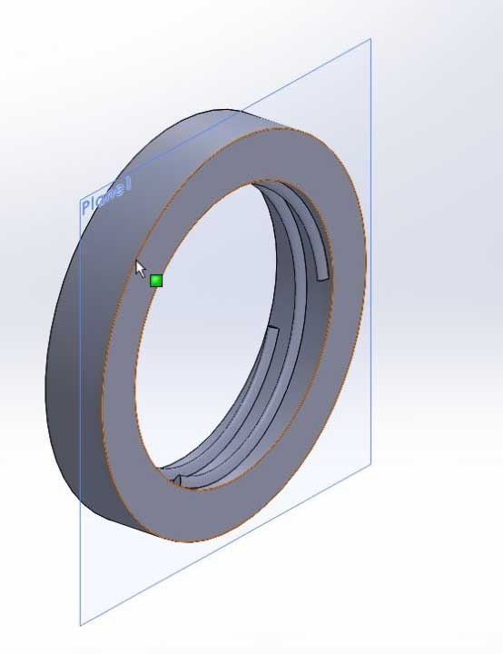
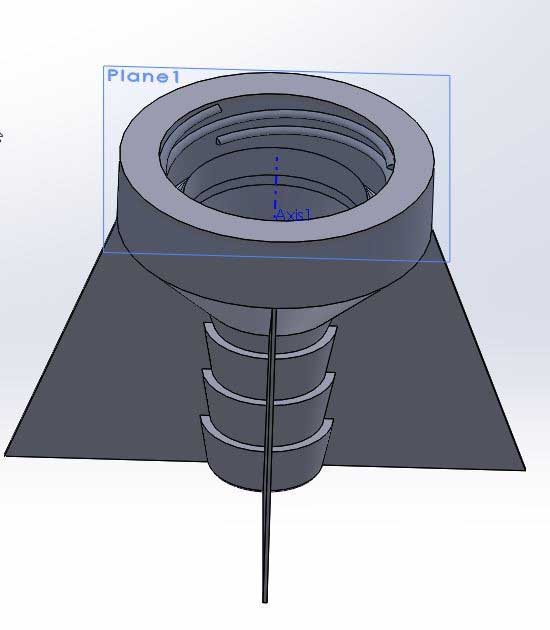
Using solidworks to design it :
Designing the plumbing adapter
I use the Helix feature for the thread :
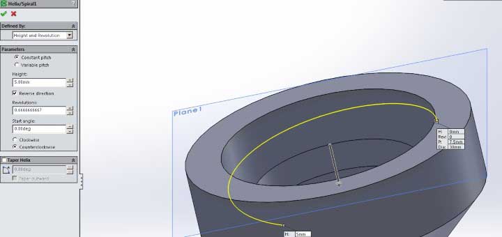
Helix feature in Solidworks
But before I print the whole system, let's make some test on the thread.
Here is the part we'll use to test :
Testing the thread
Ok so I print it, I put it on the top of the bottle, try to screw it .... and guess what... wrong way, the thread is reversed. Thanks Murphy.
Thread wrong way
So I change the design (super easy in Solidworks, two clicks with the counterclockwise/clockwise option of the helix). Again, that demonstrates here the value of designing with vector history based software.
....Print....
It works but it's super tight !
I reduce the thickness of the thread and enlarge a little the size of the inner hole. It works
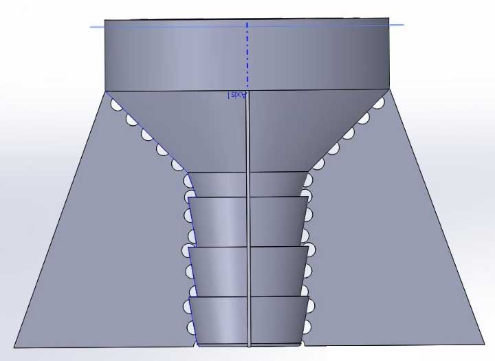
Let's go back to the full part :
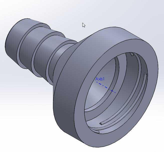
The plumbing adapter
I first tried to print it horizontally with supports :
Printing horizontally - Cura view
It totally fails
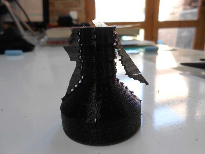
I decide to print it vertically with custom made supports :
The plumbing adapter
It prints okay but the supports are way too thick and hard to detach.
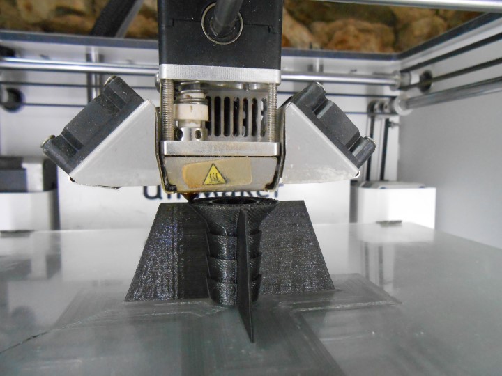
Printing with supports
I then make small holes between support and the part :
Weakening the support
Still too strong. Plus it leaves some matter on the part which is not good for water seal with the hose.
Support still too hard to break off
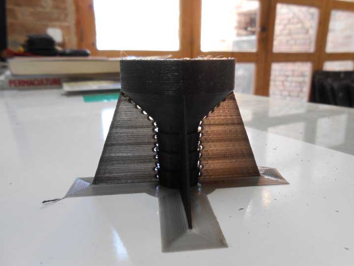
New design with tiny bridges :
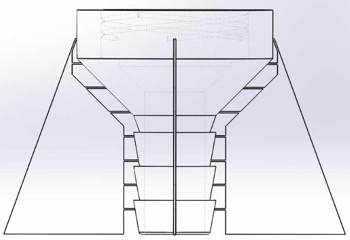
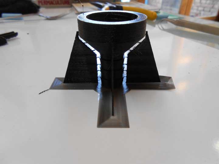
Tiny bridges work
This time it works :
The part screwed on the bottle
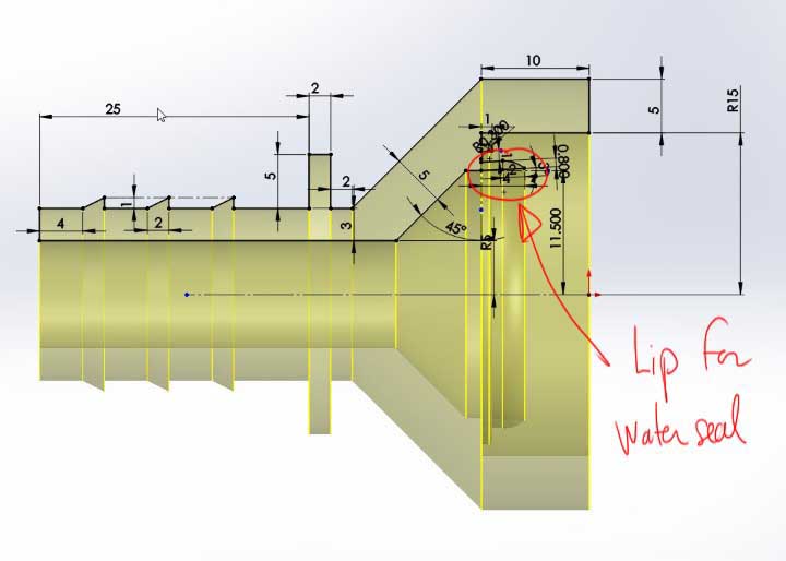
It takes 2 good minutes for the water to leak, the sealing is not so so bad. But I think I'll still use a gasket and put a flat part instead of that lip inside :
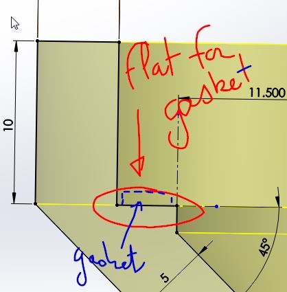
Changing the design to put a rubber gasket
So I designed and laser cut gaskets :
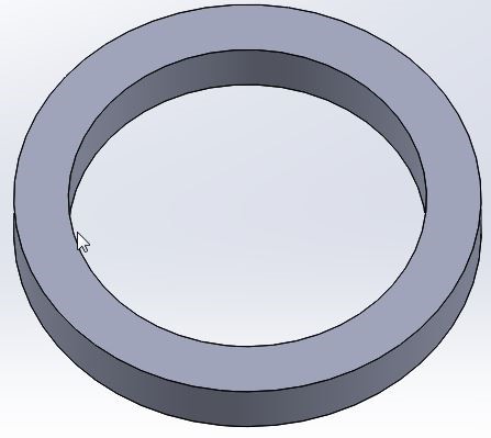
Gasket Design in Solidworks
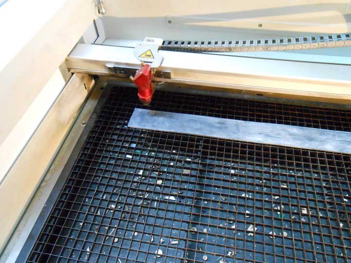
Laser cutting the gaskets
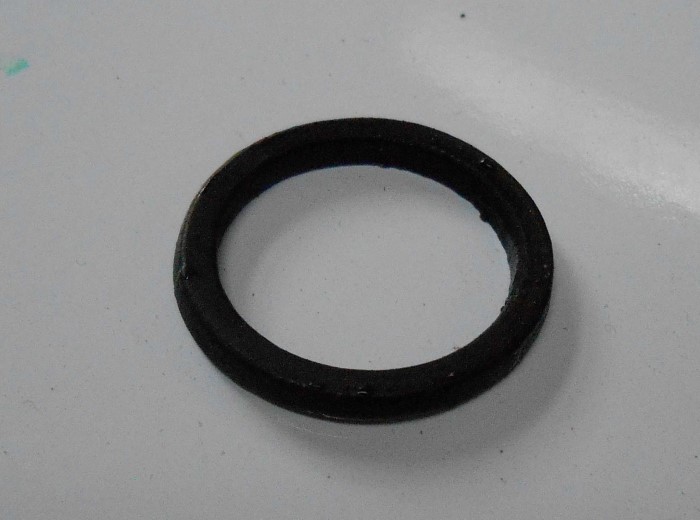
A real laser cut gasket
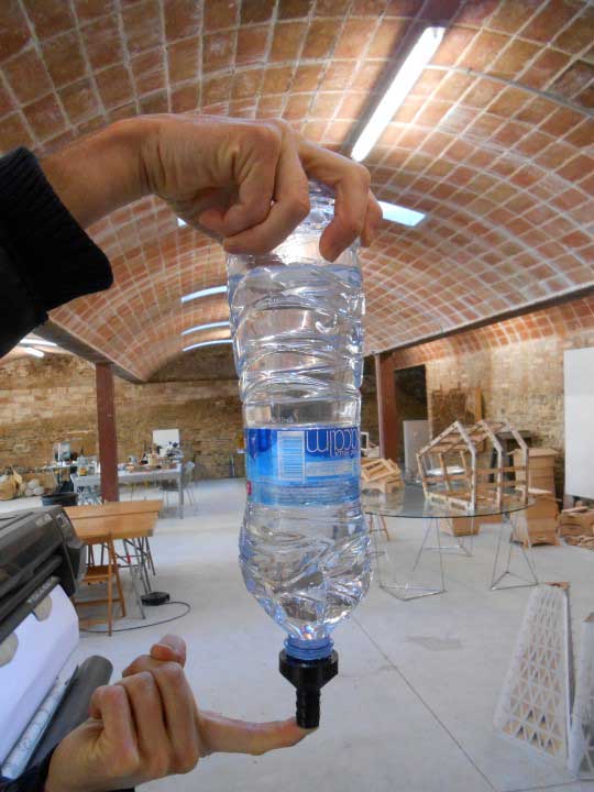
After having cut my gaskets, I put them into two new prints of my parts and here is my water level not leaking anymore !
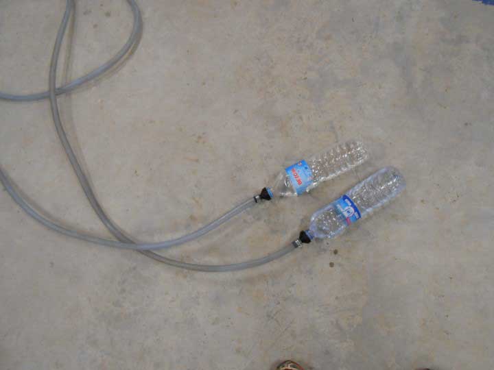
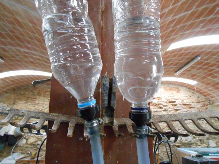
The water level
Before we jump on something else, I noticed a weird noise when the ultimaker goes along one axis. It sounds like an over-centre lock noise :
Maybe some sewing oil would do it. We ordered some.
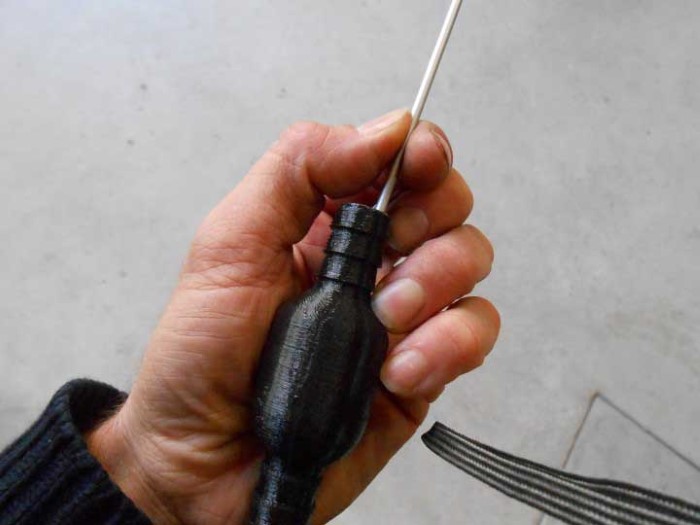
Printing a tesla valve
I also wanted to try to print a telsa valve :
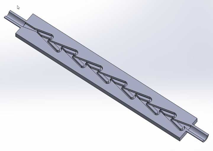
Section of the Tesla Valve
This is also a part that cannot be manufactured substractively.
After 7 hours (the valve is 20 cm long) :
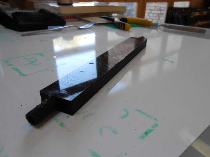
3d print of tesla valve
So it's true, it's easier to blow from one side compare to the other. But I was expecting better results.
Since I did this print overnight, I wanted to check inside. So I laser cut it :
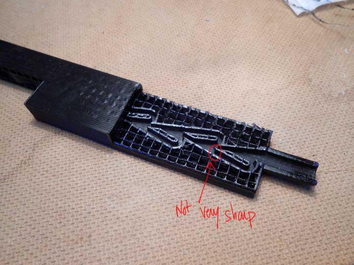
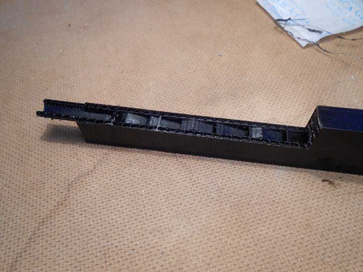
Inside the tesla valve
Maybe the not so good results are coming from the fact that the sharper the edges the better the valve works and it's hard to have super sharp edges with 3d printing.
Design and print of a fluidic diode
One thing that I might need for my final project is some sort of a fluidic diode.
I'm thinking of achieving this by having a ball allowing flow in only one direction :
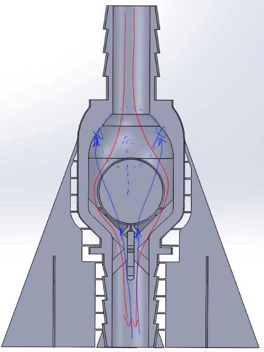
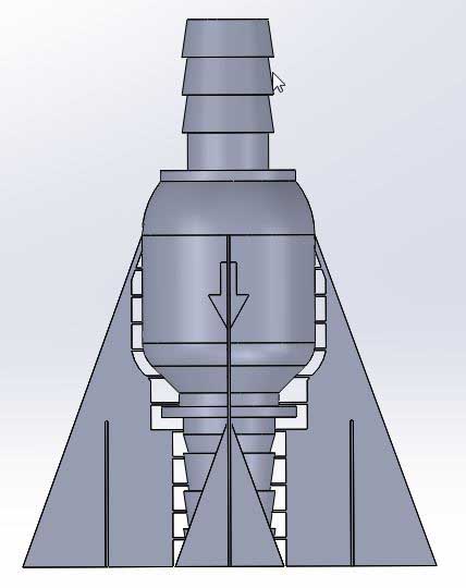
Fluidic diode design
Little support would be broken afterwards :
Breaking support after print
This is also obviously a part that couldn't be manufactured substractively.
In Cura :
Fluidic diode in Cura
The printing process :
Fluidic diode being printed
We can see the ball inside :
Ball inside being printed
The part printed :
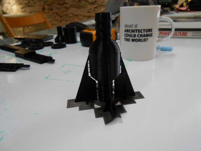
The completed print
We break the ball free :
Breaking the supports of the inside ball
We can hear it loose inside :
We can hear the ball inside, loose
Trying to blow against the arrow is clearly harder than the other way, it is not water or air-tight though.
Generating gcode with Grasshopper
Something that I didn't plan but found too tempting to resist was to try to generate my own gcode from Grasshopper
This idea came to me because I wanted to find an efficient way of creating tiny little support for my plumbing part print
I wondered if it would be possible to print "in the air" kind of like the 3Dpen :
So I experimented with this idea and was successful to generate valid gcode but my spiral didn't really work
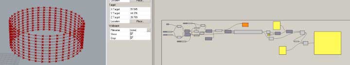
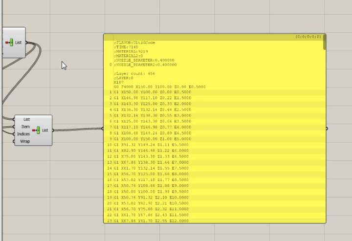
Generating Gcode in Grasshopper
Here is the lame try :
Lame 3D helix printing in air
I'm pretty sure I need to lower the speed and increase a lot the "E" (extrusion) value in the gcode.
3D scan with Kinect
Then I played with the Kinect to 3D scan.
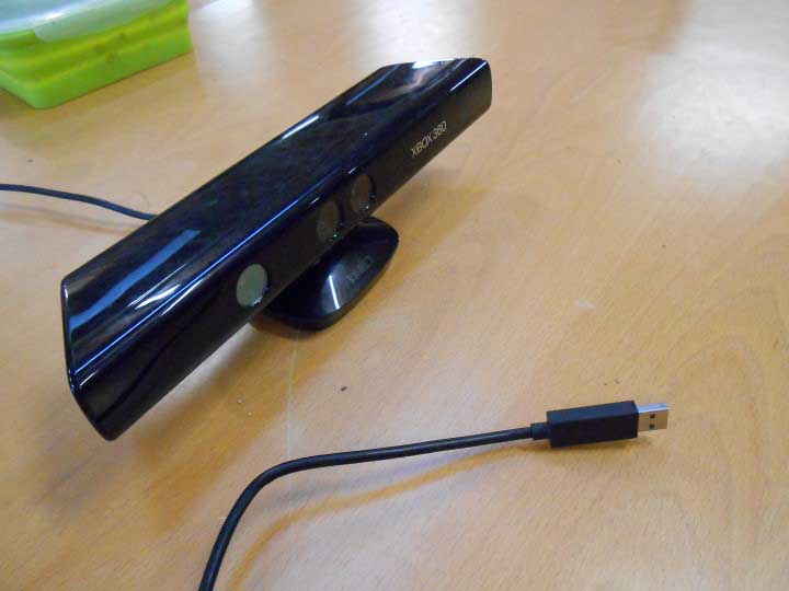
the Kinect
I used Skanect as scanning software.
There's also ReconstructMe which allows the use ot AMD (previous ATI) video cards.
I noticed that because it works with infrared, the Kinect doesn't really work in the sun or bright light (actually "warm light"). So I went for a rather dark place :
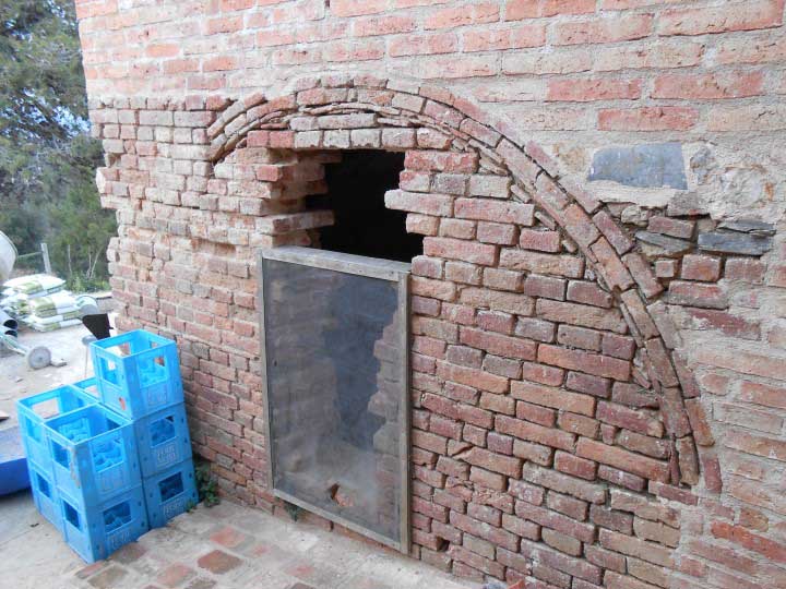
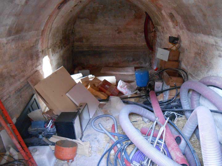
The scan object : a cellar
So with the help of my icelandic academy mate Guðjón Logi Haraldsson, we scanned the cellar
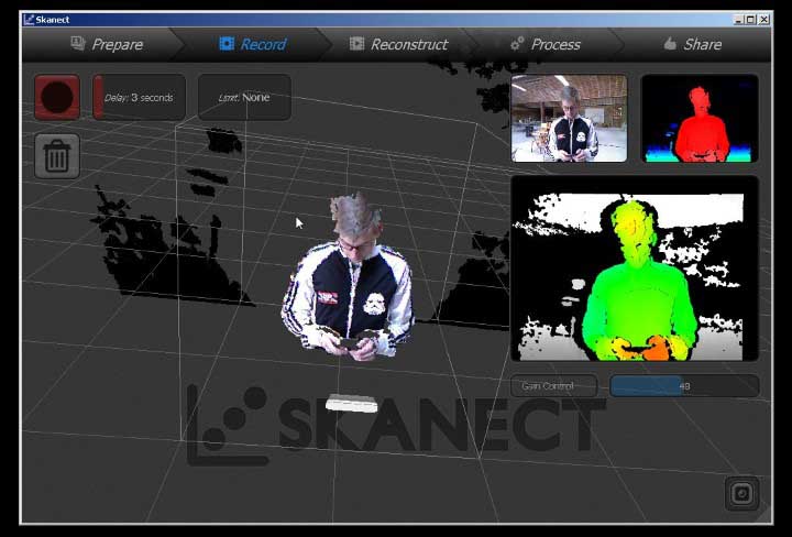
My friend Guðjón Logi Haraldsson in the Skanect interface
and here is what we got :
The 3d scanned Cellar
3D scan with 123D Catch
Lastly, I played with 123D catch.
It's a photogrammetry software from autodesk which uses the power of cloud computing to recreate a 3d model from a set of images taken with our camera :
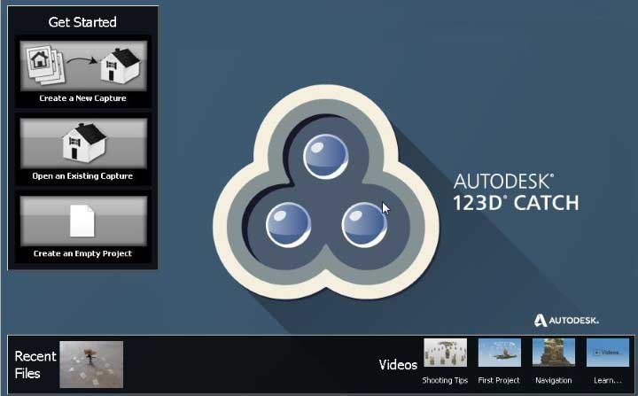
123dCatch interface
It's super easy. We take pictures, upload them and receive the model.
Here are the three basic steps :
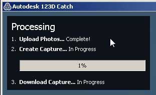
123dCatch simple steps
Here is what I wanted to scan :
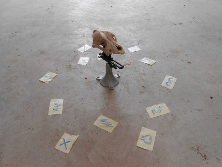
The skull I will scan
The little pieces of paper on the floor are trackers that will help the image processing
After an hour of cloud computing, I got this :
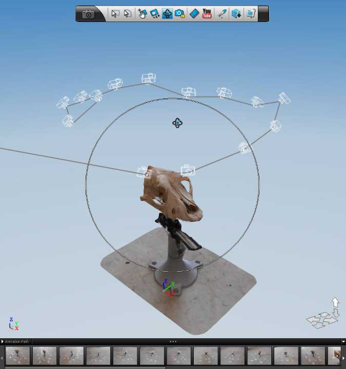
The model received back from the cloud computing
Editing it in Max to remove some faces :
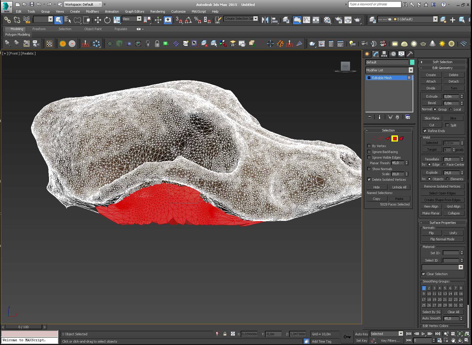
Editing the model in 3dsMax
And then, rendering it !
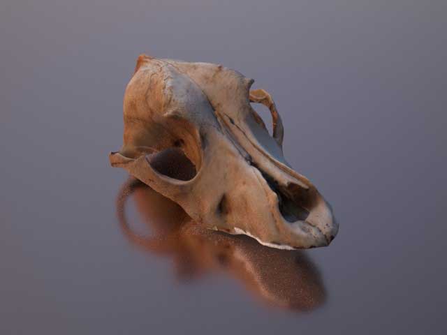
Render of the skull
Here you can play with it in 3D :
Skull by Gregoire Durrens on Sketchfab
Source Files
Here are the sources files of the projects I talked about on this page :
SOLIDWORKS - Thread test
SOLIDWORKS - plumbing part
SOLIDWORKS - tesla valve
SOLIDWORKS - Fluidic Diode
GRASSHOPPER - Helix
STL - plumbing part
STL - tesla valve
STL - Fluidic Diode
OBJ - Skull
Conclusion
- It's really important to keep in mind how the part can be 3D printed, the design rules, when we design and model it.
- It's hard to get sharp edges with plastic extrusion 3D printing
- We don't have to go through a slicer to generate gcode which is basically a text file. There is other ways, like scripting with Grasshopper
- The Kinect is great for scanning meter scale object. As it uses infrared, it works best in a cold, dark environnement that is not saturated with infrared.
- The quality of photogrammetry and its easy process is impressive, at least in 123D Catch.
***