Week 12
molding and casting
Assignment
- design a 3D mold, machine it, and cast parts from it
Week workflow
Here is how I see the week's flow :

Flow chart for this week
Table of content :
- Defining the part
- Designing the molding and casting strategy
- Drawing the different parts
- Making the mold parts
- Casting the desired part
- Source files
STEPS
Defining the part
I've been working with a friend, Mauricio Cordoba, on his 1 dollar water filter project : FairCap.

The Faircap project webpage
FairCap was one of the 12 projects selected to participate in POC21.

FairCap at POC21
Now the idea is to prototype a filter that adapts to plastic bottles and small pipes allowing at the same time the use of a new unexpensive porous tubing technology.
The new filter
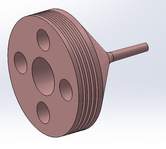
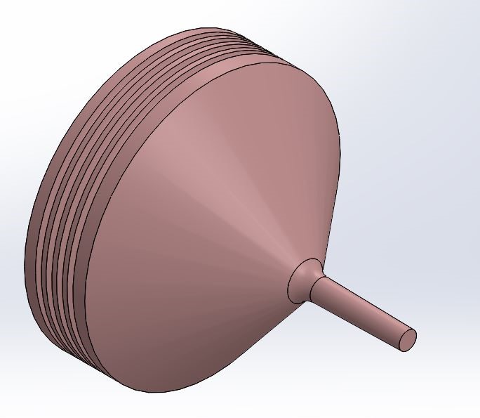
We'll mold and cast this part, the "multi-adapter" :
The multiadapter part
The porous tubes :
Porous fibers that filter at sub virus size with great flow
Here is a section of the whole system :
Section of the filter
Again, we'll focus on the side multi-adapter
Here is our part to cast :
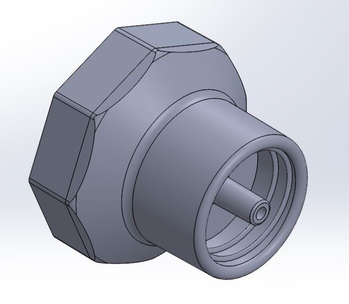

multi-adapter part
Designing the molding and casting strategy
Before jumping on the design I read this guide, the guerilla guide to CNC machining.

Guerilla guide index
Aside from the information that was given to us from the fabacademy course, there is some great explanations in it, like this one :

Molding and casting strategy
Also, doing the Solidworks tutorial on molding was good :

Soliworks Tutorial
A great tool in Solidworks is the drafting analysis :
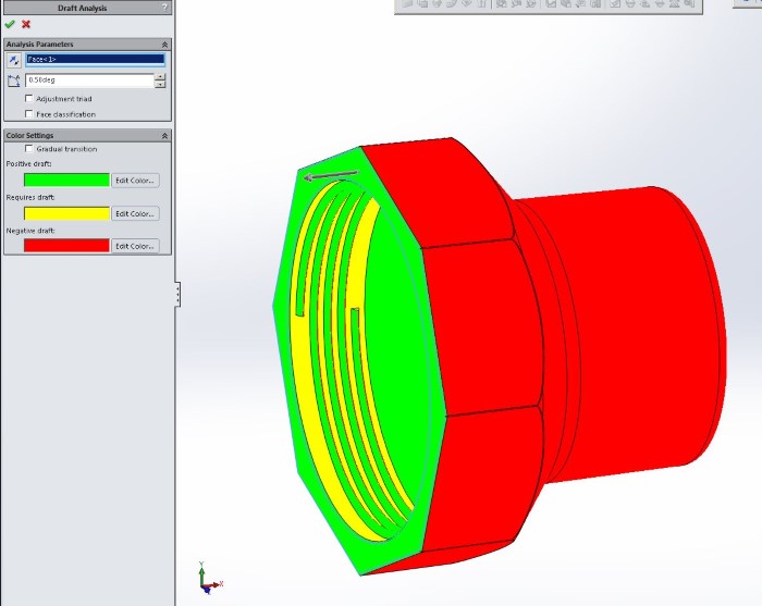
Drafting analysis tool
It allows us to see how the demoulding would go, and then help us doing slight angles on either part of the split between the two mold sides.
After tweaking the part, here is what shows the drafting tool :

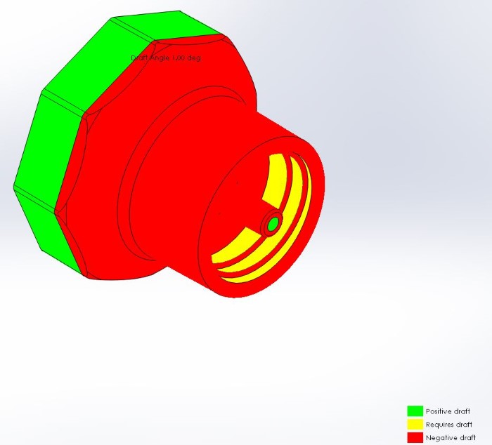
Final draft
Something that we also have to take into consideration when we design the mold is the angle that we need to make on the vertical faces for milling the deeper surfaces
Indeed, the bits need to have room to go down without colliding on other faces of the part.

Angle limit induced by tool shape
In Solidworks, I do a quick sketch to find the angle based on measurements on the bit.
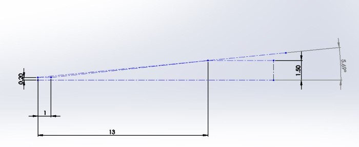
Finding the angle in Solidworks
Going mentally through the process of demolding, I realize that the threads that are present on both side fo the part will make it impossible to demold by sliding with hard material for mold.
Not only this, but machining the thread with 3axis CNC seems to be impossible. We need to cast a mold part.
So two ideas :
- We could unscrew a hard mold part from the final cast part.
- Or we could cast this mold part with silicone and squish it to take it out.
I choose to go with the Silicon idea :

The complete mold
Drawing the different parts
So here is an exploded view of the parts I need to make :

Exploded view of the mold
The silicone parts are mold parts that will be removed by squishing them and pulling them out.
Silicone Negative of side 1
Silicone Negative of side 2
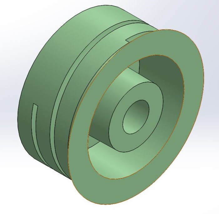
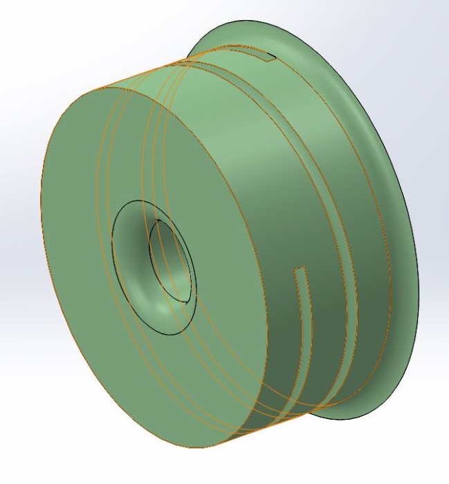
I'm drawing positive parts that are simpler versions of the final part.
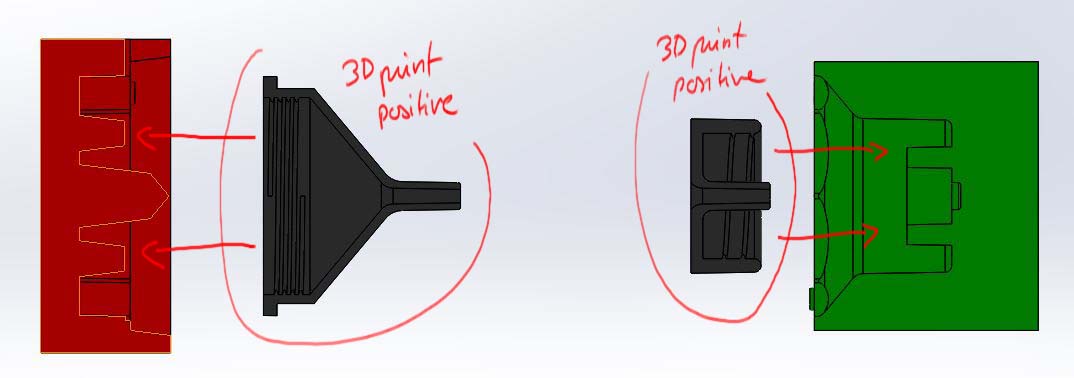
Positive parts for casting silicone mold
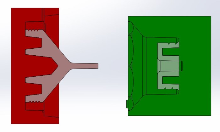
They will be used as positive molds for casting the silicon negative mold :

Positive parts in place
Then I will remove them and I'll be left with just the mold parts I need to cast the final part.
Exploded view of the silicone + wax mold
I just have to put the two sides together.
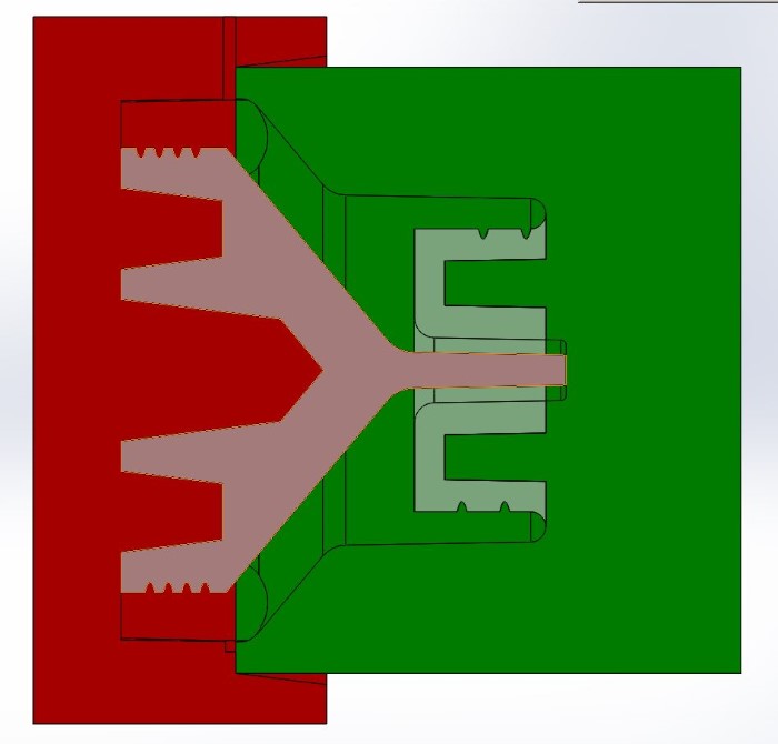
The mold, closed
I give a 0.1 mm play for the right faces to be tight, not all of them :

Play for getting tightness only on the closing mold faces
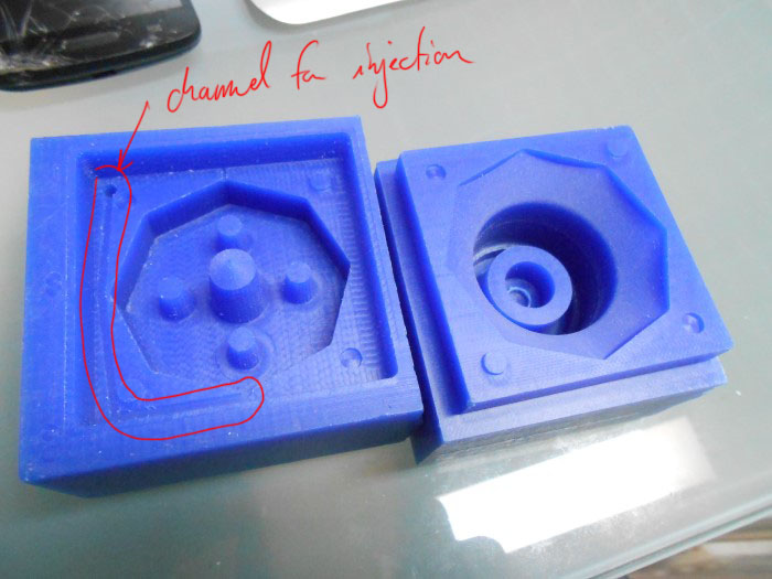
I also make channels and vent for injecting the liquid plastic.

One side of the hard wax mold
I guess it's better to fill from the bottom to the top to prevent trapped air.
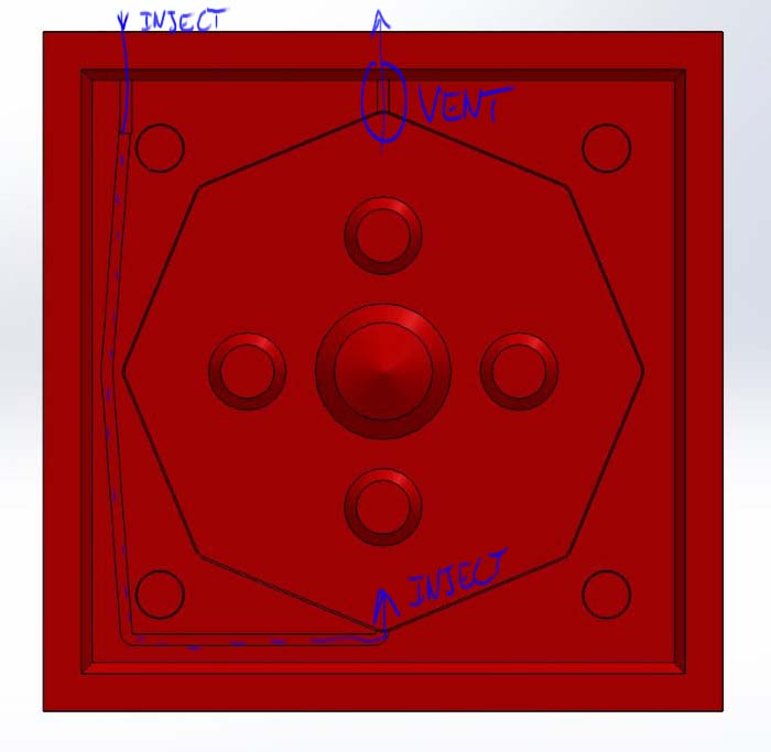
injection channel and vent
Same thing for the other side :
The other side of the hard wax mold
Here is a video of how the mold works :
How the mold works
Making the mold parts
I start by 3Dprinting my positive parts (the black ones on the picture shown earlier).
One for the "green" side :
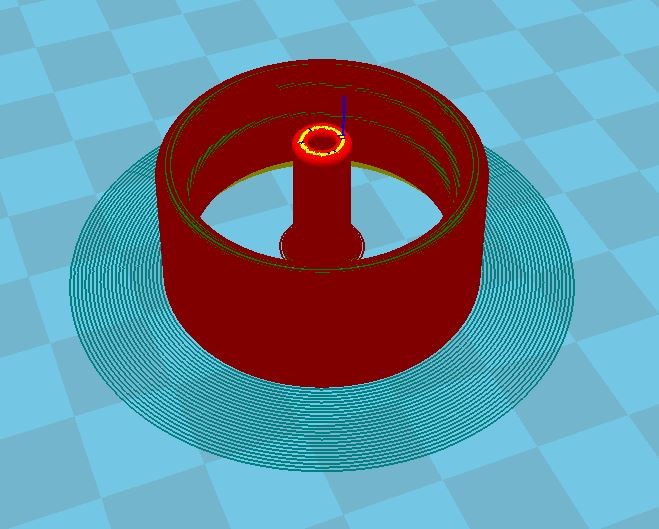
Positive part - side 1 - in Cura
And for the red side :

Positive part - side 2 - in Cura
The prints :
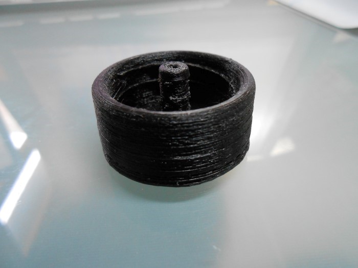
The printed part 1

The printed part 2
Then I generated the toolpath for machining the hard wax mold part.
For this, I need to export my geometry. A convenient thing to do is to create a coordinate system that outputs our part in the right orientation and position according to the software we use to generate the toolpath.

Setting a new coordinate system for export
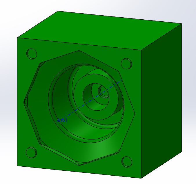
I use Rhino and RhinoCam to generate the toolpath.

mold part imported in Rhino
Here are the machining jobs :
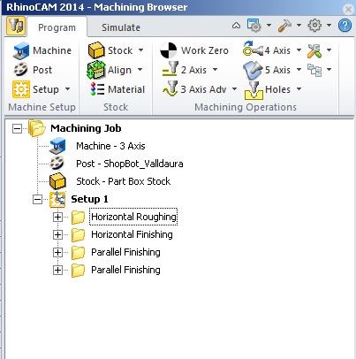
The machining strategy
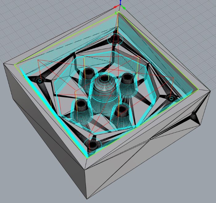
And the toolpaths that were generated with their simulation :


horizontal roughing
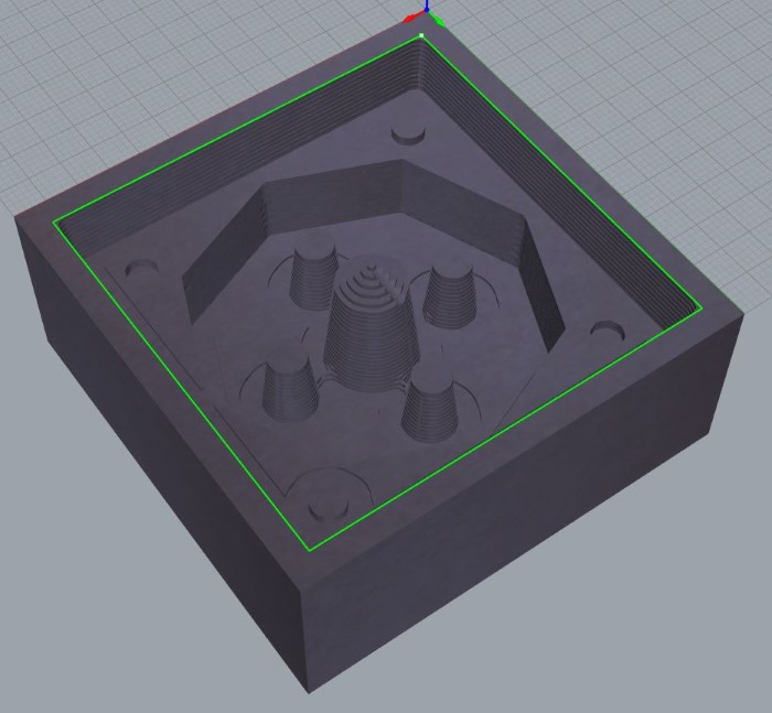
Horizontal Finishing
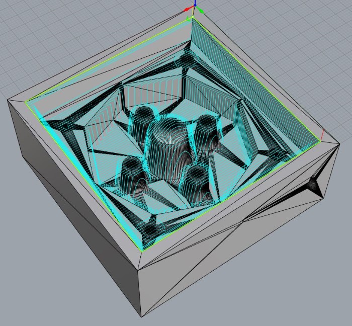
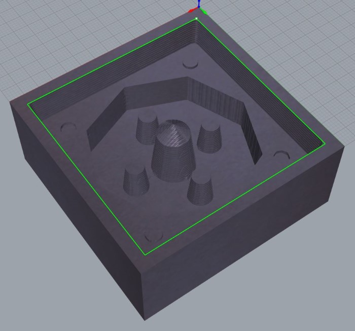
Parallel Finishing
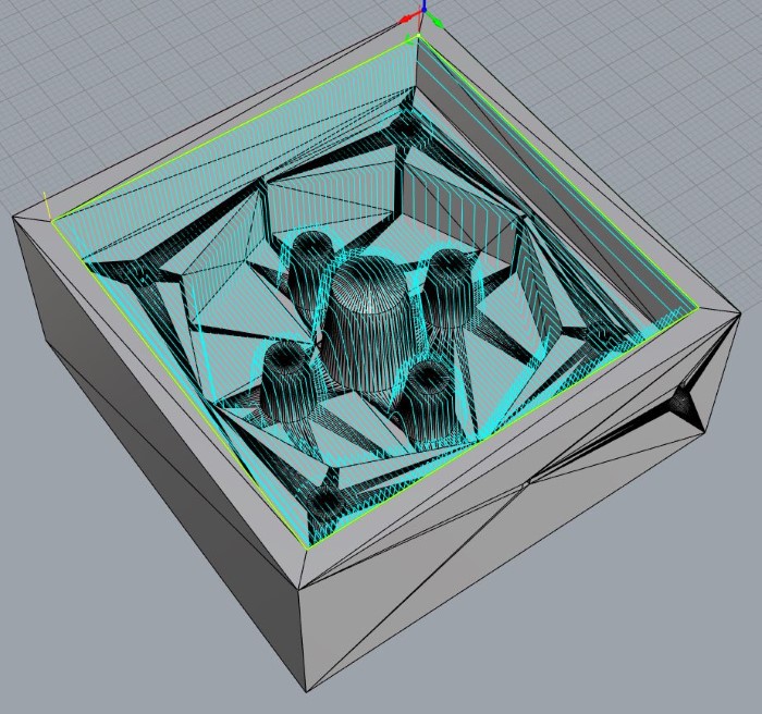

Parallel Finishing 90°
Just to check I also played with fabmodules :
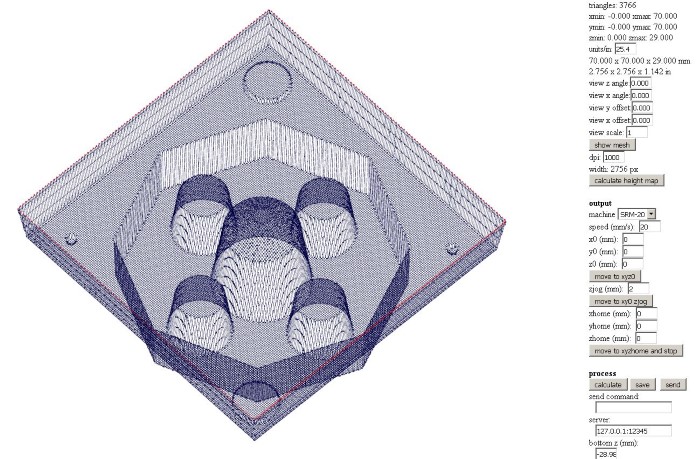

Fabmodules gcode for milling wax
It looks alright, I like how it's very simple to use.
I first need to cut a piece of wax that fits the mold part that I will mill :
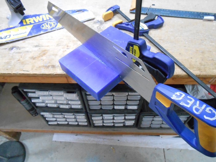
Cutting pieces of wax
Then I position it in our Monofab milling machine :
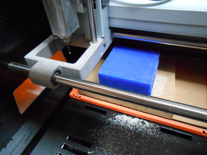
Positioning the wax piece
Here is a video of the first machining job, roughing :
Roughing operation
The result :
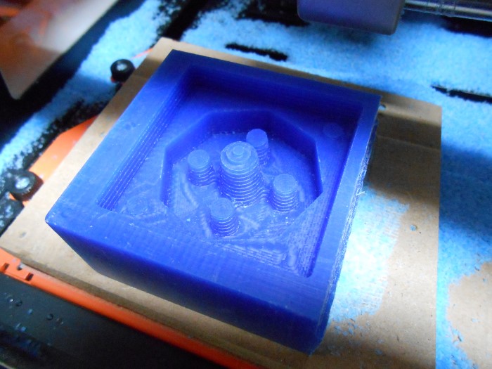
Result of the roughing operation
The second operation is horizontal finishing. Here is the result :

Result of the horizontal finishing operation
Then we have the two parallel finishing operations.
On one of the mold parts, I also generated a toolpath and milled a channel with a 1/32" bit for injecting the plastic.
Here are the two parts at the end of the process :
The two hard wax mold parts
The mold closes perfectly :

Closed Mold
Casting the desired part
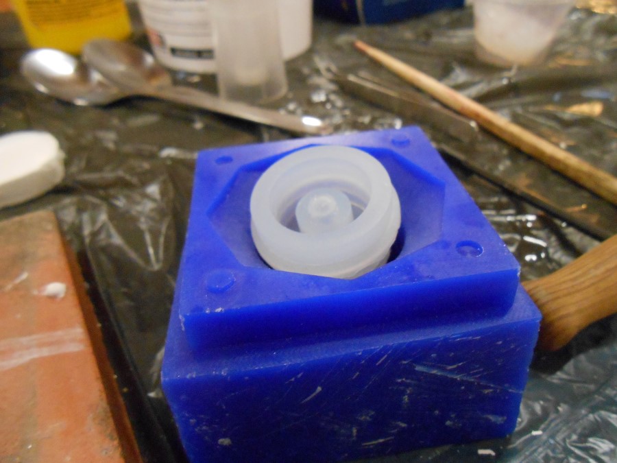
I pour the silicon in one of the mold :
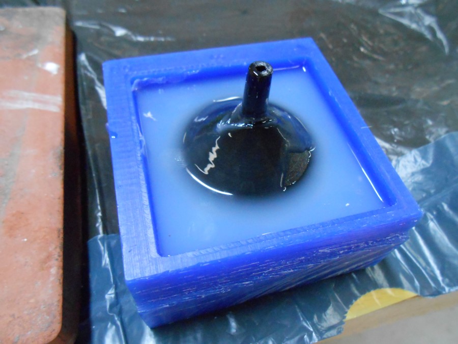
Legend
I obtain the internal silicone negative :
Legend
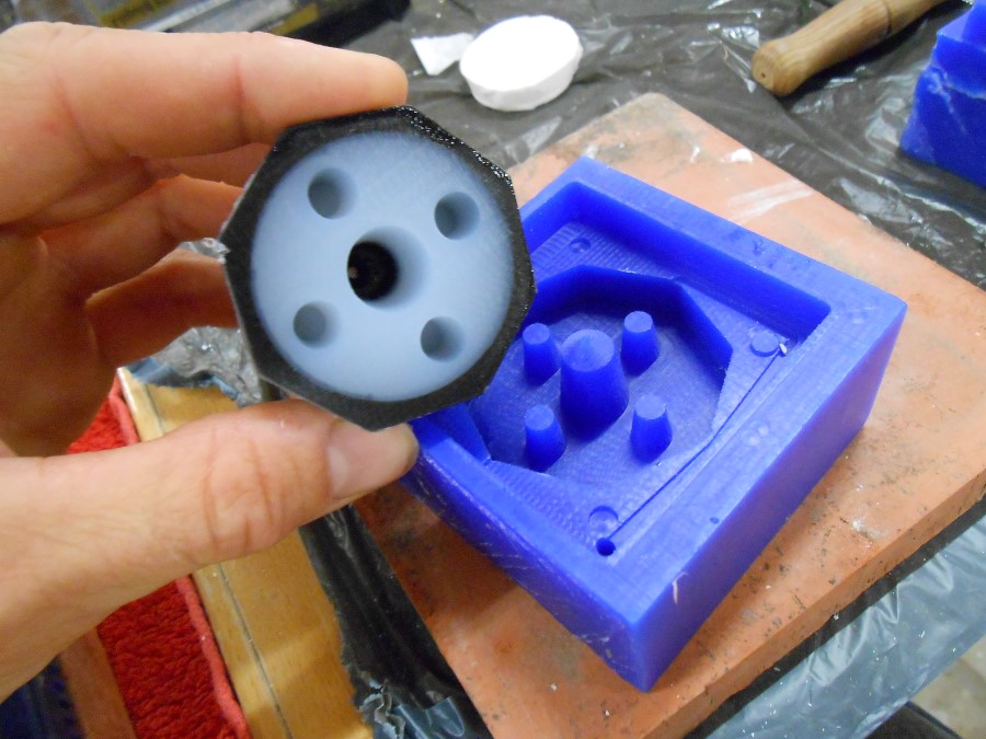
As wished, I'm able to take out the silicone negative off of its 3D printed positive counterpart :
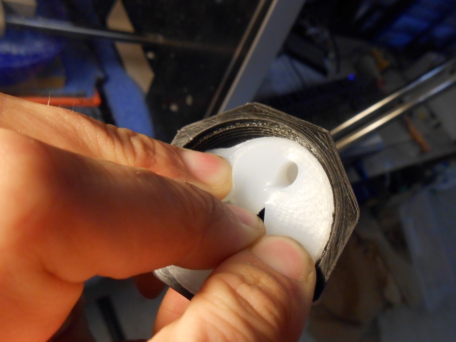
Legend
This Silicone part will then be the internal negative for our multiadapter.
I do the same for the other side :
Legend
Now, I just need to cast liquid plastic with these silicone internal negatives at the center of the two parts mold.
I didn't have the time to do this but you can check my final project page for a similar casting.
Source files
Here are the sources files of the projects I talked about on this page :
SolidWorks files
If you feel like contributing, please fork from Github :
Conclusion
...
***