Week 3
computer-controlled
cutting
Assignment
- design, make, and document a parametric press-fit construction kit
Week workflow
First and foremost, I would like to thank Jonathan Minchin for being so available and letting me use the lab at undecent hours.
Jon, if you ever read this, thanks mate!
Here is how I see the week's flow :
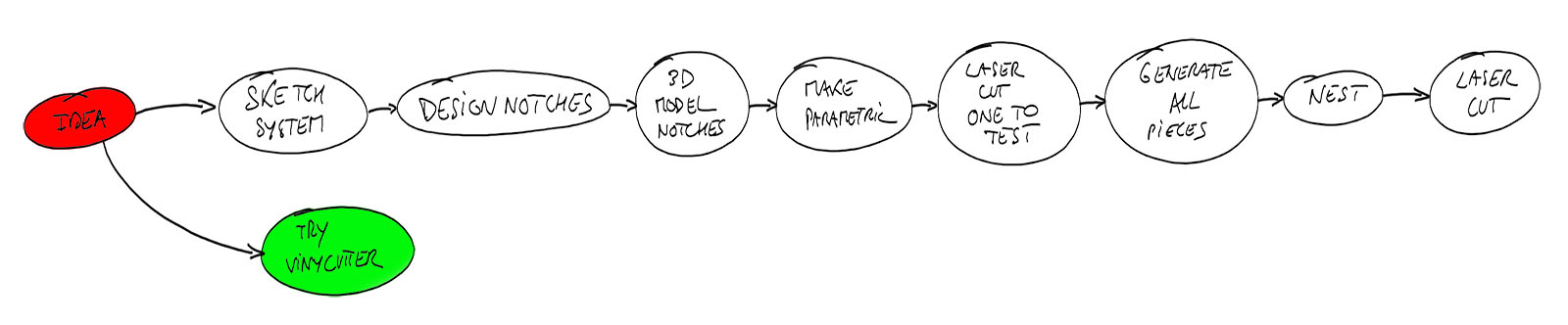
Flow chart for this week
Table of content :
STEPS
Design
Nitinol, which is the alloy I'll be using in my final project, fascinates me. I found myself wondering about crystallographic arrangements of atoms.
That inspired me for the press-fit construction kit. It would be nice if we could have a simple way of building molecules with cardboard.
Here are some sketches I did :
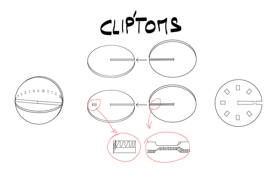
Design sketches
I started to model the part in 3D using Solidworks :
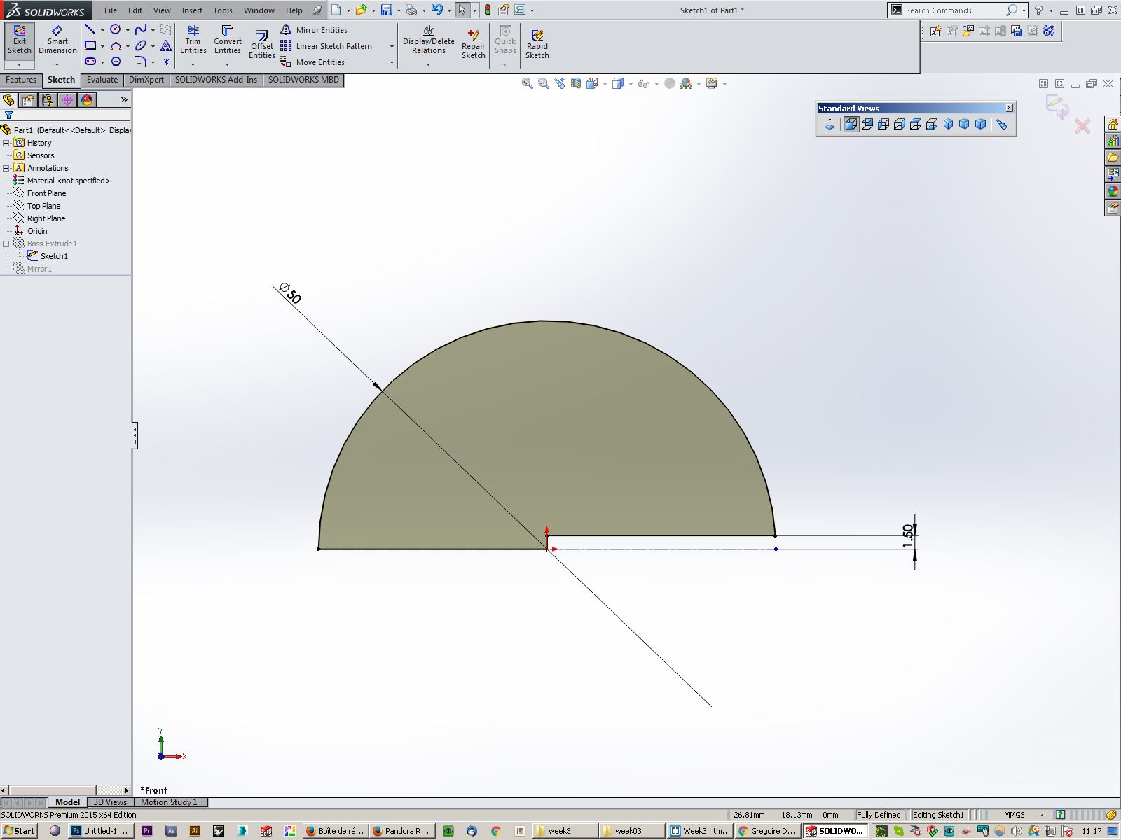
First sketch in Solidworks
When I was happy with my part, I did a assembly to try out how the part fit together.
I'm using an advanced mate feature : "Width". This is very convenient for adding parametric clearance later.
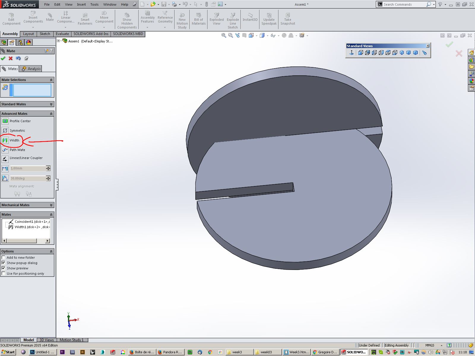
Assembly in Solidworks - "Width" Mating
You have to select the two faces that are going in between the two other faces :
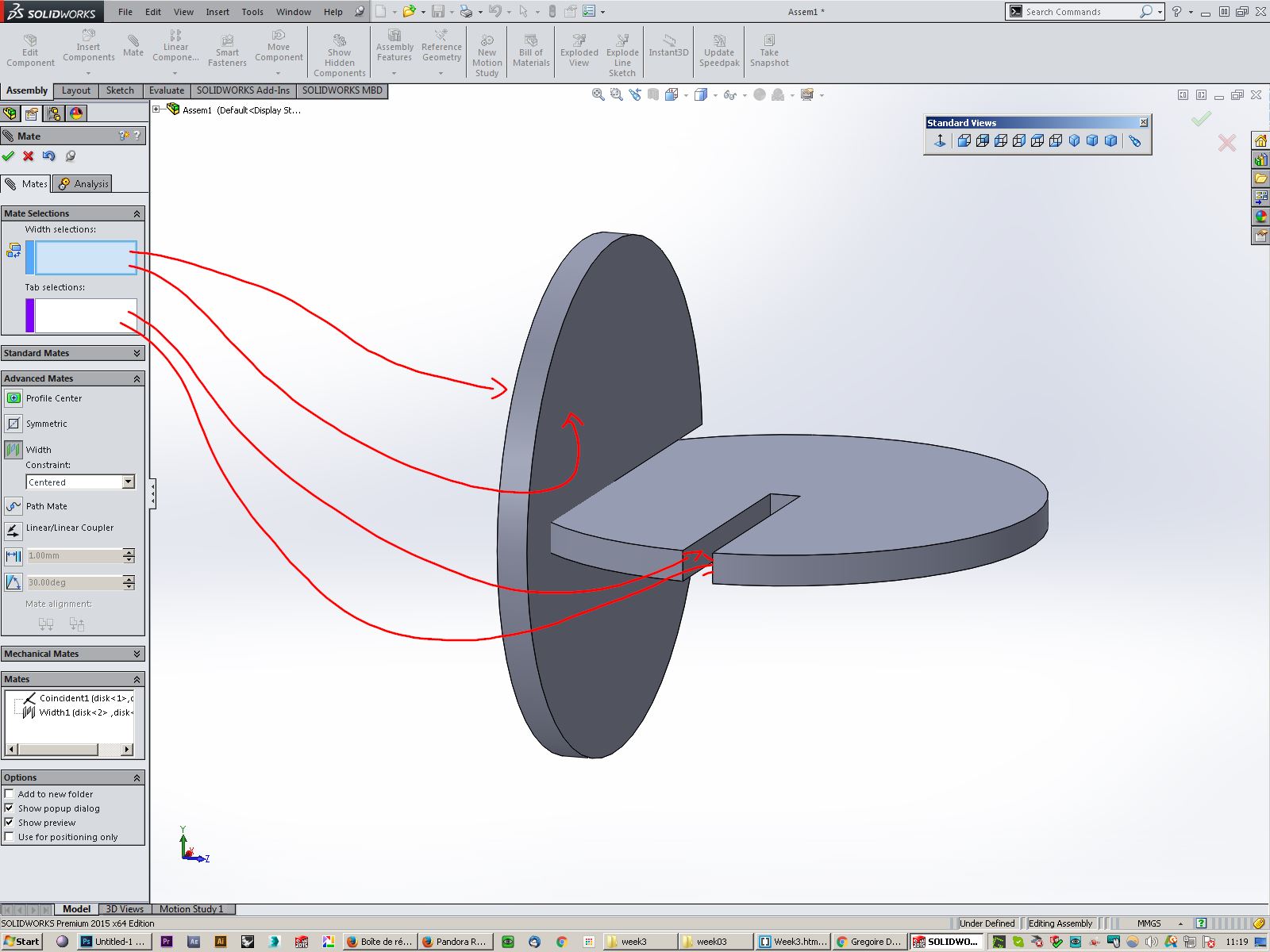
Width mating - Selecting faces
Here is the result:

Width mating - Result
It looks like my fitting system works.
Let's make it parametric. For this we'll use equations :
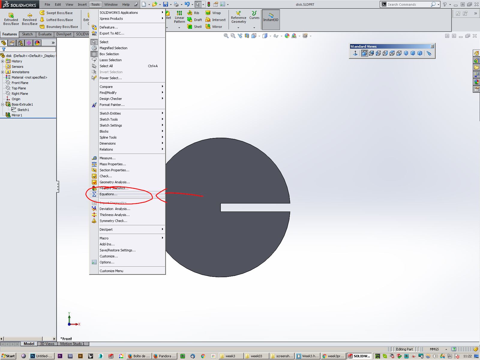
Equations menu
We'll start by adding global variables that define our model:

Adding Global Variables
Then we'll add equations to the dimensions in our sketch.
Right in the sketch viewport we can add equations that are using the global variables :

Dimensions driven by equations
Adding a parametric clearance gives us the ability to quickly change the tightness of the notches. This helps a lot to find best parameters for a type of material, here cardboard. That's when the "width" mating feature is useful since the clearance appears on both sides :

Parametric clearance
Once we're happy with our design and the way it's parametric, we can export the parameters in an external text file :
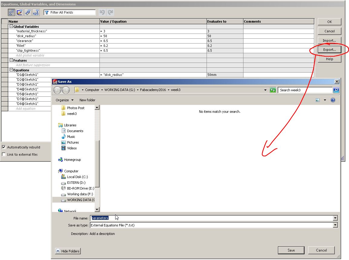
Exporting Parameters
We choose the global variables that are our parameters :
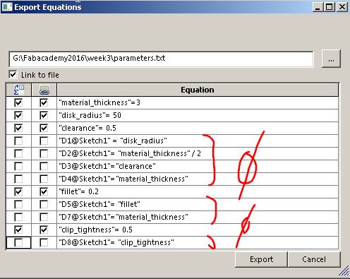
Choosing the parameters we want to modify in the text file
Once we've done that, these parameters are linked. This means that if we modify the text file, Solidworks will automatically update the global variables.
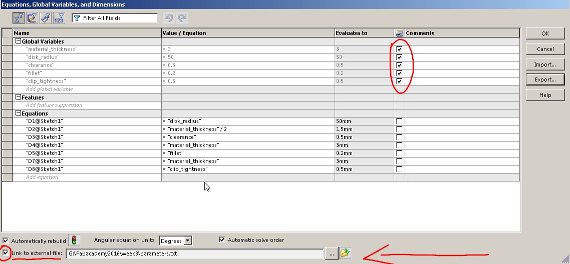
Linked parameters
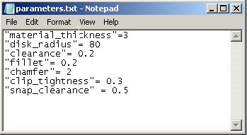
If we change the text file. We have to save it and rebuild in Solidworks :
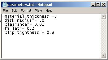
The external text file with our parameters
Rebuilding in Solidworks
Using the circular pattern feature, we add notches around for more possibilities.
We can see here that changing the original sketch allows us to complexify in an instant the whole assembly. Here is the power of NURBS and history based modeling.
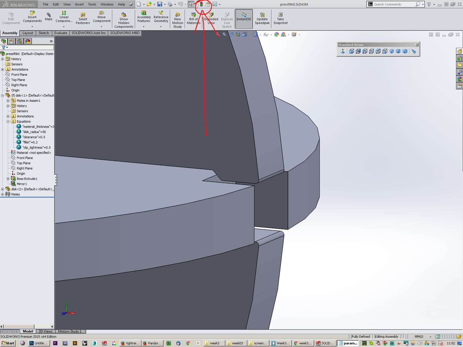
Here is the assembly done with the "width" mating for the notches :

More complex assembly - Overlapping parts
We can see that the part are overlapping.
This is exactly where parametric is very handy.
I just have to go to the text file, change parameters, save and rebuild to find what works well for this thickness of material.
The cardboard I'll be using is 3mm thick.
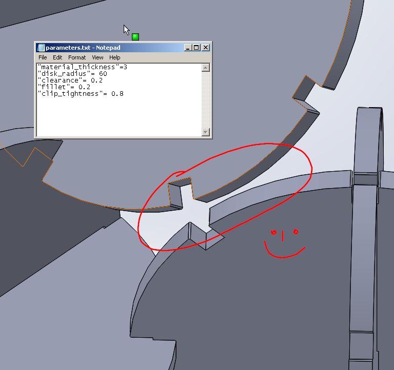
Using the text file to update parameters
Here is a video that shows the changing parameters process :
Vid.1 - MIT's worm robot
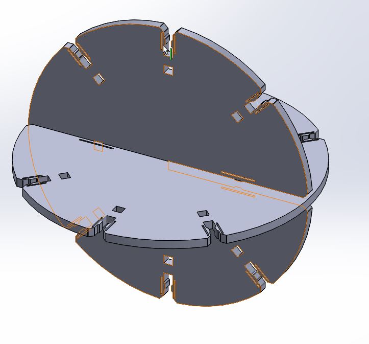
So here is our first final version V1 :
The dents are here to snap parts in place and prevent them from sliding off.

Final version V1
Proof of concept
We are now ready to make our first test !
We need to export our design for the laser cutter.
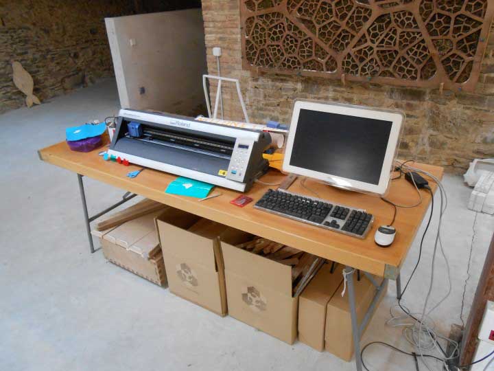
We'll use a Trotec speedy 400 laser cutter :

Our laser cutter at the Greenfablab
On the computer that is linked to the Trotec laser cutter, we "print" from Inkscape to fire the software "JobControl X" that drives the speedy400.
So, back to solidworks, we'll use the drawing feature of Solidworks to generate a file that we'll open in Inkscape.
Solidworks drawings are very handy because they update automatically with the changes we make on the 3d model.
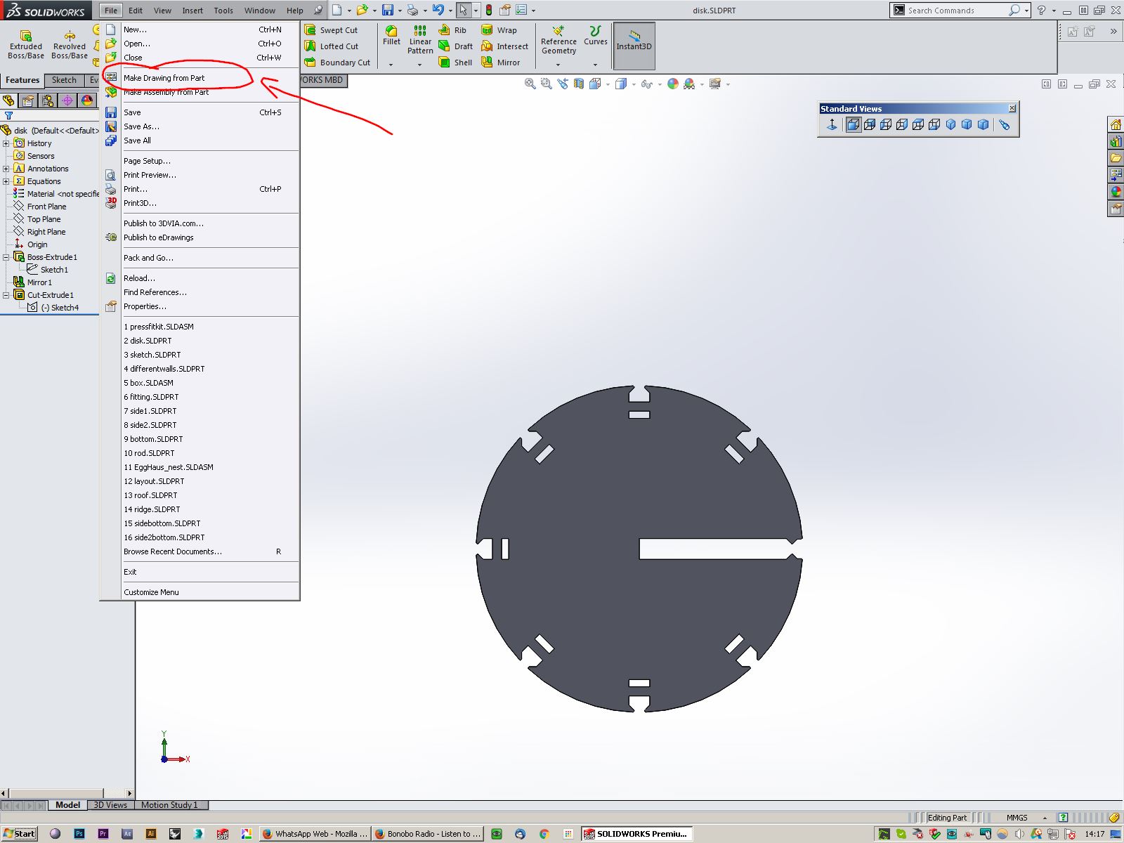
Creating a drawing
We add a view :

Here a front view is added to the drawing
I first export the drawing in DXF format and import it in Inkscape.
I make a clone since we need at least two parts to test.
In Inkscape I'll set two different colors to my lines. Indeed, colors encode what kind of operation the laser driver will do, what kind of laser parameters will be used and in which order.
We can then have a color-coded strategy :
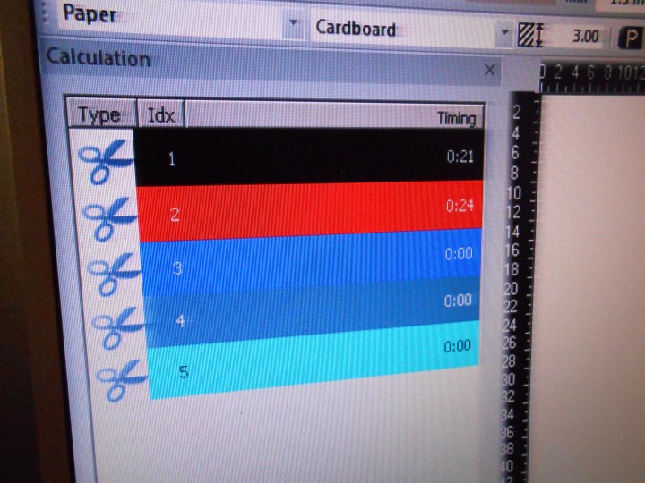
Tooling strategy in JobControlX for Trotec
In our case, in JobcontrolX, the software driving the laser, the color black is treated first, then red.
We want the holes to be cut before the part outline is cut. This is to prevent misalignment once the cut part have dropped by few mm depending on how unflat the cardboard sheet is.
Here is how I color code in Inkscape : the black color to every hole and then red to the outline
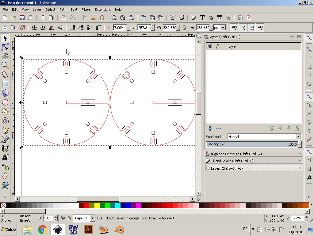
Different colors define an operation order
Once we're ready, we "print" from Inkscape.
That fires JobControlX in which we can place our cut where we want on the cardboard sheet :
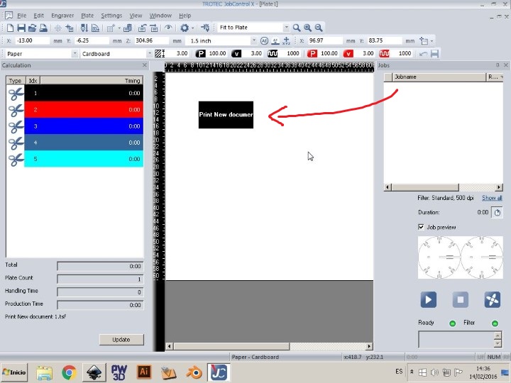
Placing the job on the sheet
Now, before we start the cut, we need to make the "focus". The laser lens has to be at a focal length away of the material for the laser to be fully efficient. Otherwise the cut is not proper.
But we can also play with the defocused laser for interesting effects, ling heating only for bending acrylics.
The trotec has a little tool that helps us doing the focus. Hung on the side of the laser, when the bottom touches the material as we bring it up, it loses balance and fall. That indicates we're at the right distance.

The focus Trotec tool
making the focus with the trotec tool
We can sort of doing this by eye also. We just have to find when the pilot laser dot is the smallest. And in my case, the little tool from trotec was wrong. I think it matches another lens.
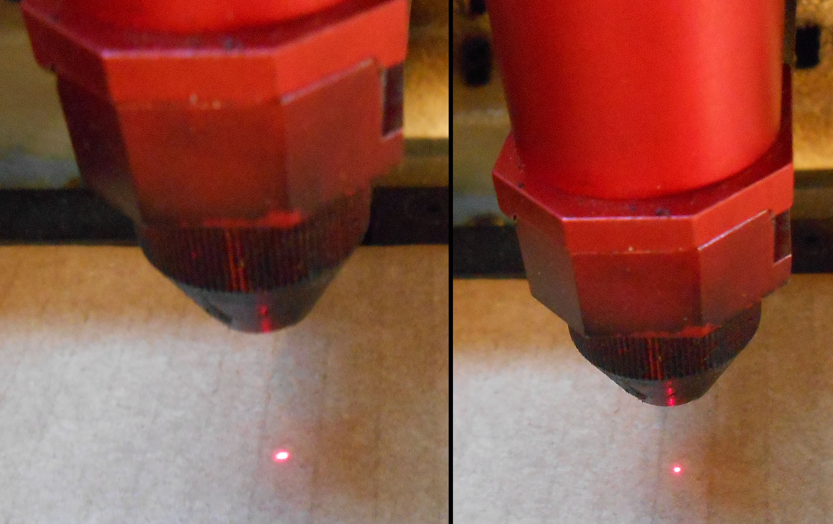
The focus by eye - In focus on the right
Now has really come the time of the cutting :
Laser cutting - Real speed
Here is the result :
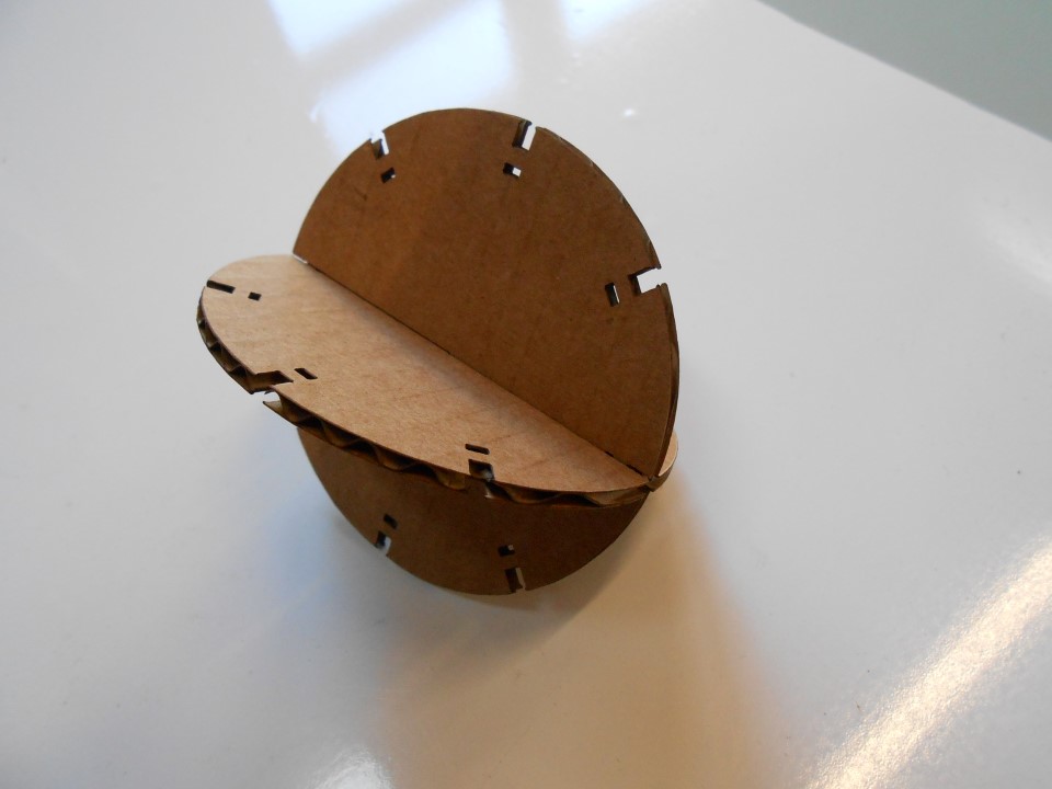

The two disks assembled in two different ways
Obviously there are several problems.
First, the tightness has to be adjusted.
Also, the scale is not good !
The scale problem was coming from a bug in Inkscape. The import dxf function doesn't import to scale 1:1 but 1:1.05
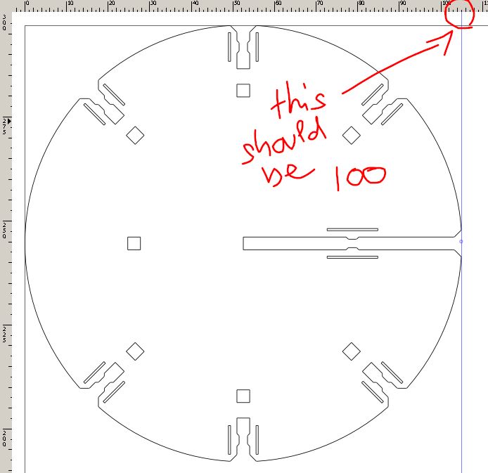
Scale Problem when importing dxf
I reported the bug to the inkscape team :
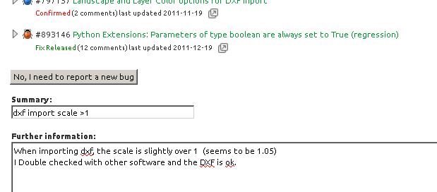
Bug report for Inkscape
Then, after trying many ways of getting around the dxf import problem, here is my workflow :

Export/Import Process
Rhino is useful for "joining" continuous lines and make selection easier.
I can then easily change the colors.
Editing in Rhino
I export in Pdf from Rhino :

pdf export
I finally open that in Inkscape on the trotec computer and laser cut it.
After several versions, I'm pretty happy.
Version 7 is the one :) .

Different testing versions
I added some "cuts" next to the dents to allow the cardboard to slightly bend.
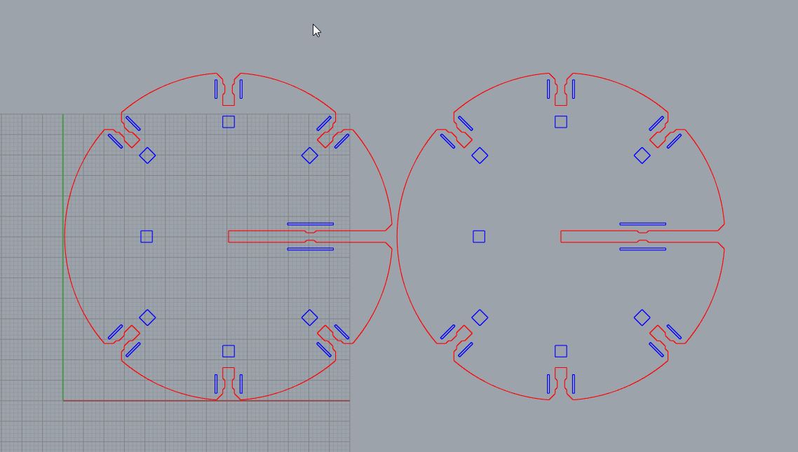
Here is the final design, the one of version 7 :


The final version for testing and its parameters
Make
Now we're ready for some fun !
Let's cut the complete kit with different sizes.
Since the assembled "spheres" represent atoms, let's find out what are the most commun atoms in our galaxy :
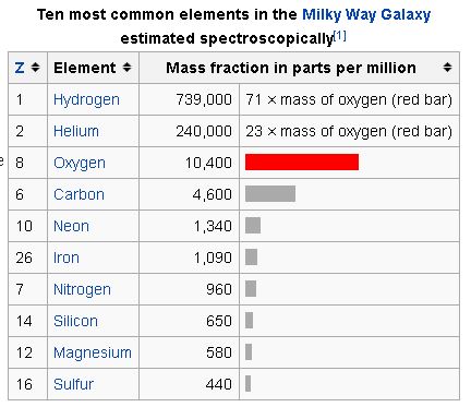
source : Wikipedia
Here are their radii, in picometers :
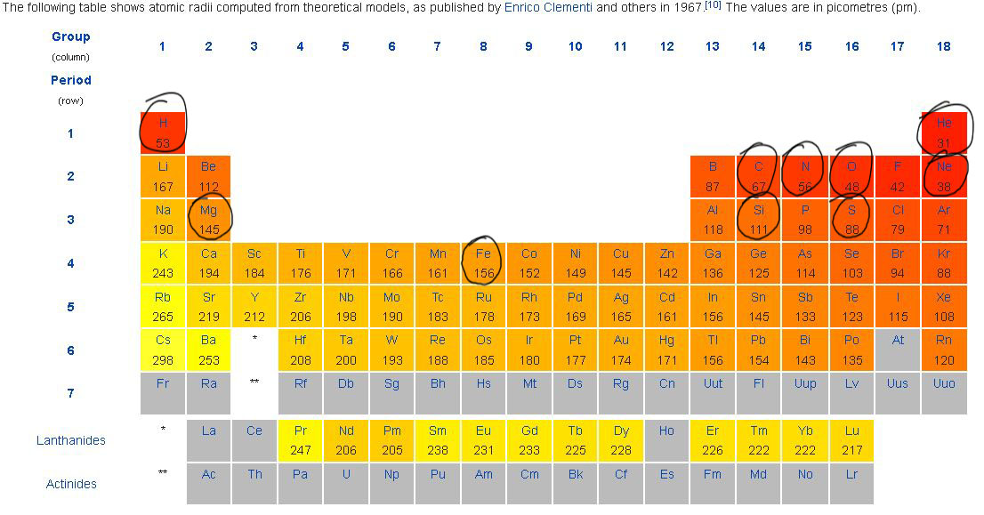
Atoms radii - source : Wikipedia
I find that 70 mm is my minimum diameter before the design stops working properly.
So, according to the table above, the other radii are proportionally:

GoogleDoc sheet to calculate the different atom radii
So, in Solidworks, I did an assembly with all my different "atoms" using different configurations. That fully takes benefit of the parametric design.
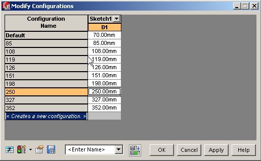
Solidworks configurations changing the atom diameter parameter

Atom Assembly in Solidworks
And exported it to Rhino..

Atom Assembly in Rhino
It's good to nest them this way they take the least amount of material.
Plus, when there is a lot of different parts to nest, it's tedious to do it by hand
Here are some free ways to do that :
- by hand
- Grasshoper can help the nesting with a program called GENERATION
- SVG nest
- E-nesting.com
- Mynesting.com
The E-nesting service seems to be always busy...
The Generation component for Grasshopper is working but I didn't find it was giving good enough results. I'm sure we can improve my algorithm inspired by Antonio Turiello.
Let me show what I did though :

Grasshopper Nesting Algorithm
Nesting Result in Rhino
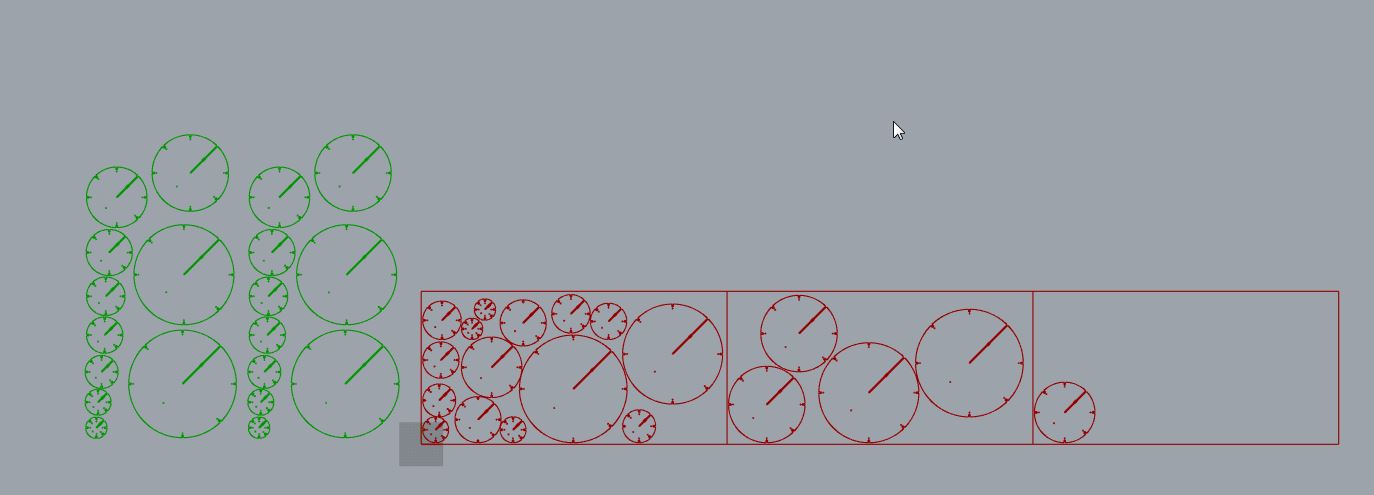
So I tried the MyNesting software.
MyNesting would do the nesting but you can export only once for free.
Without exporting it's still a very good help to find a good nesting solution and then manually place your parts.

"MyNesting" interface
Back to Rhino with my nesting solution from MyNesting
Nested solution imported in Rhino
First thing I do, and this is kind of a common thing, I select everything, split and join to get nice polylines.
Split and Join
Now has come the time to set the correct colors!
This one is a little tricky cause we have many parts whose outline should be red and all holes black to have the correct cutting order.
Doing this by hand is not easy. That would mean selecting all the holes and set their color to black, and do the same for the outline in red.
Also, it would be nice to be able to move the parts as groups for fine tweaking.
That's where Grasshopper become very handy.
Here are algorithms I did to group and affect colors based on if the curve is an outline or if it is inside of an outline.
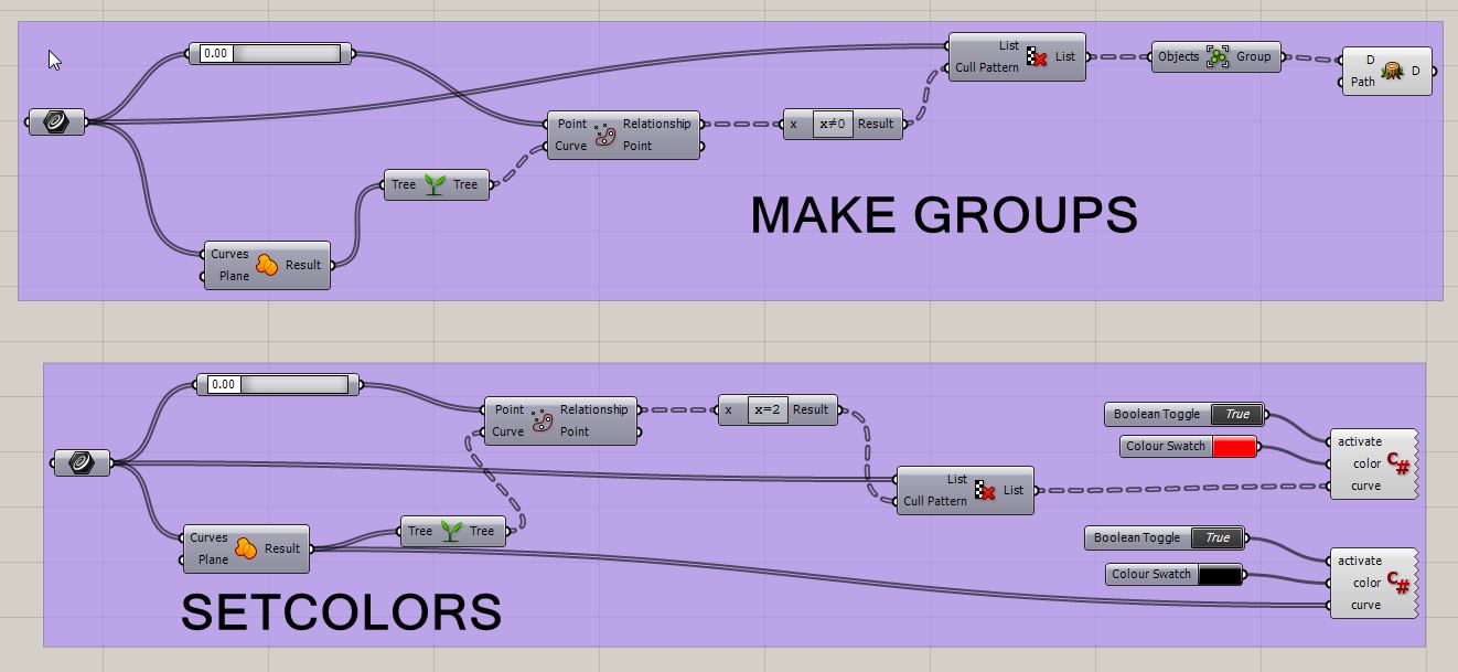
Grasshopper grouping and coloring Algorithms
Like with the nesting algorithm, I basically make a union on every curve to find the outlines. Then I check for all the curves if their are inside or outside of these outlines to make groups or define their color.
At the end of the setcolors algorithm, you can see a C# module. I had to write this one to be able to "bake" (that's a grasshopper term) my colors to the current layer.
Here is the code :

Grasshopper C-sharp Component source code
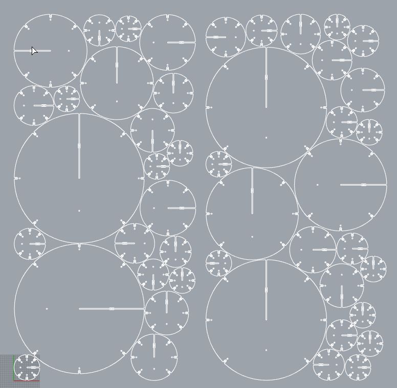
Once I baked all my curves, I Split-Join them all again, and I get this :
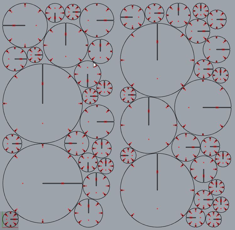
Curves ready to be cut ("printed") in Rhino.
So here I could print right from Rhino.
But if I wanted to go through SVG, there is some issues :
- Rhino doesn't know how to export SVG. (There is a very nice open source Grasshopper SVG exporter though!). The only problem with it for us is that the exporter split the path in many different smaller paths which is what we don't want.
- The export-import dxf alternative generates many split segments in inkscape which makes that there is no junction between the segments :
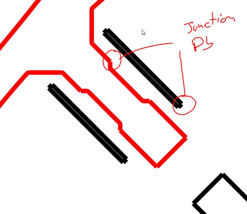
Junction issue after importing DXF in Inkscape
To overcome this I use the select same function by color in Inkscape to select all my red curves :
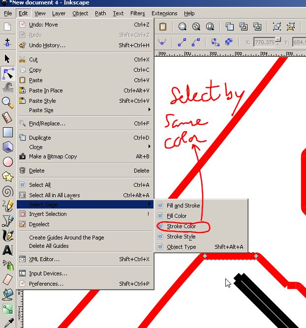
Selecting all the red curves
Then I move them to a layer that I previously created "red".
I do the same for the black curves on a "black" layer.
After this, I hide either one of the two layers my curves are on and I select them all.
If I select them all again (Ctrl-A two times) the nodes with bezier are selected :

Selecting all the nodes
Then I press "Join" :

Joining all the paths
I do the same for the black curves and I get a file that only has one path per closed curve, which is nice for the laser cutter cause the paths are smooth.
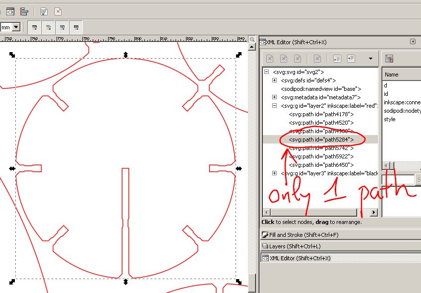
One path per closed curve

Smooth paths
Finally, I load my Rhino or Inkscape on the laser cutter computer and cut it as described earlier.
There is one difference though. Because I use large sheet of cardboard sometimes the sheets are not perfectly flat. That can be annoying because the laser gets then out of focus. One trick I found is to simply put some paper tape folded in half at the bottom and I stick the cardboard to it wherever the sheet is slightly curved upward :

The tape trick
There is two sheets of 1m x 0.5m in total to cut my press-fit construction kit.
Here is one :
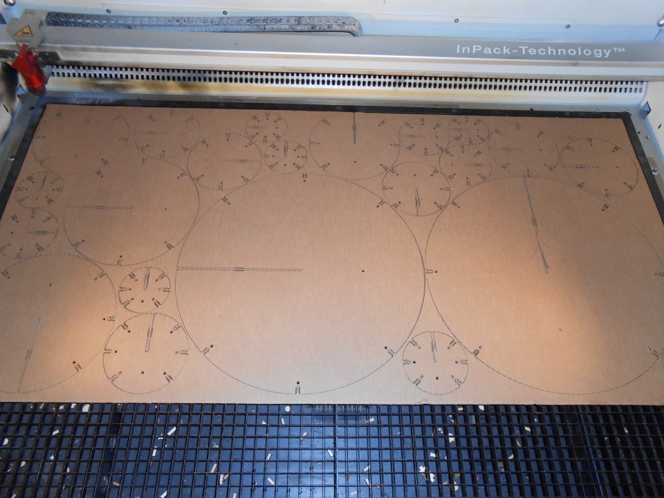
Cut Sheet
Let's play now :) ! ......
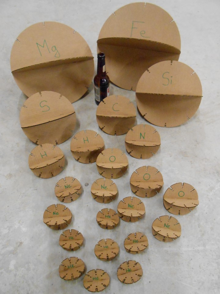
My Clip'toms
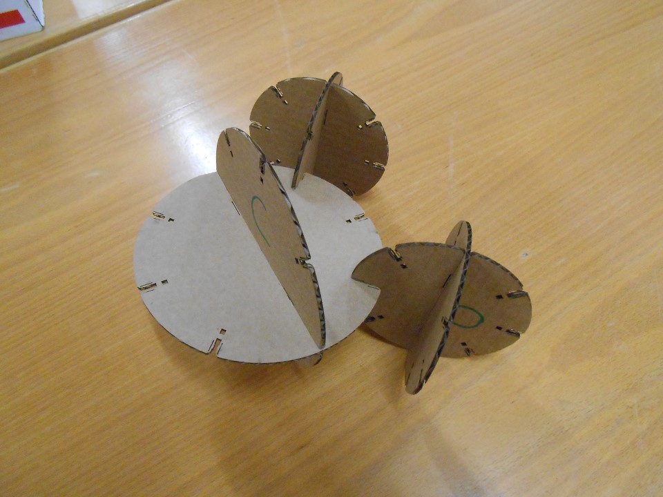
CO2 molecule

O2

Water
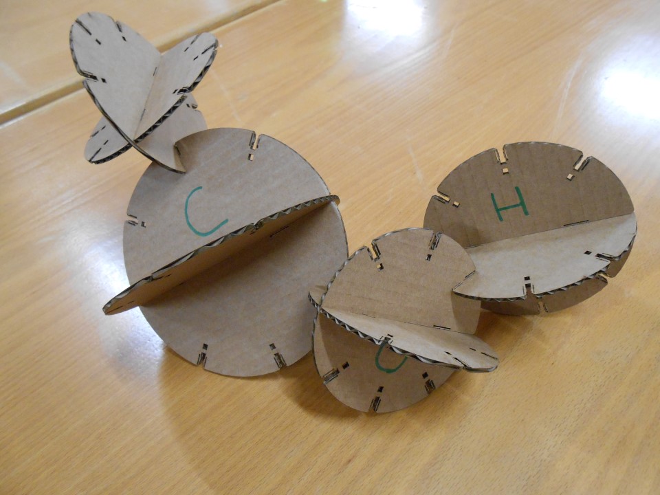
Must not drink too much of this !
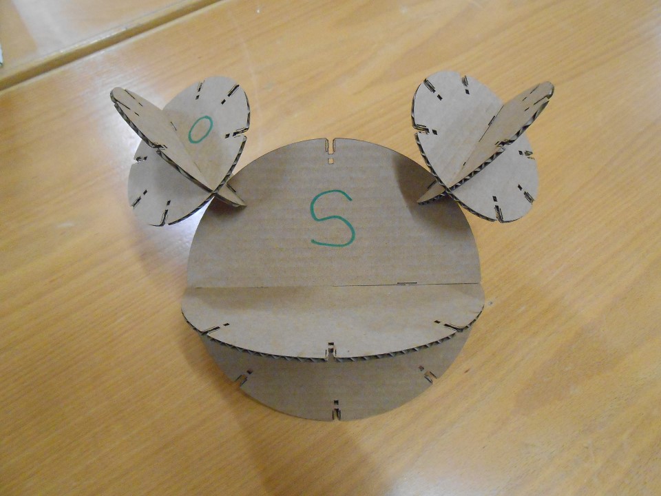
Sulfur Dioxide (shouldn't drink this at all)

FeMgSiSCH2NO3Ne5He7 - the maker's cutting madness molecule.
Vinyl Cutting
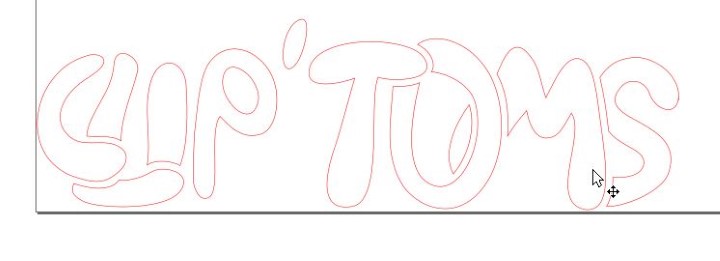
I wanted to tune my press fit construction kit a little up by putting its name on it. Perfect for Vinyl cutting.
I start drawing the letters in Inkscape and tweaked them with the edit paths tool :

Letters drawn in Inkscape
I then edit the parameters suitable for vinyl cutting with the Roland we have here in the Greenfablab : full red (255,0,0) and 0.5 pixel thickness for line width :
Finished svg in Inkscape
We have the Camm-1servo :
Our Roland Vinyl cutting machine
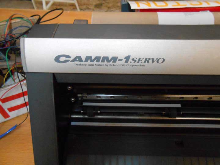
The Camm-1 Servo
We use Fab modules to generate the tool path :

FabModules program interface
Here is our little Camm cutting Vinyl :
The Roland Camm in action - cutting Vinyl
I then transfer the cut Vinyl on my biggest atom :
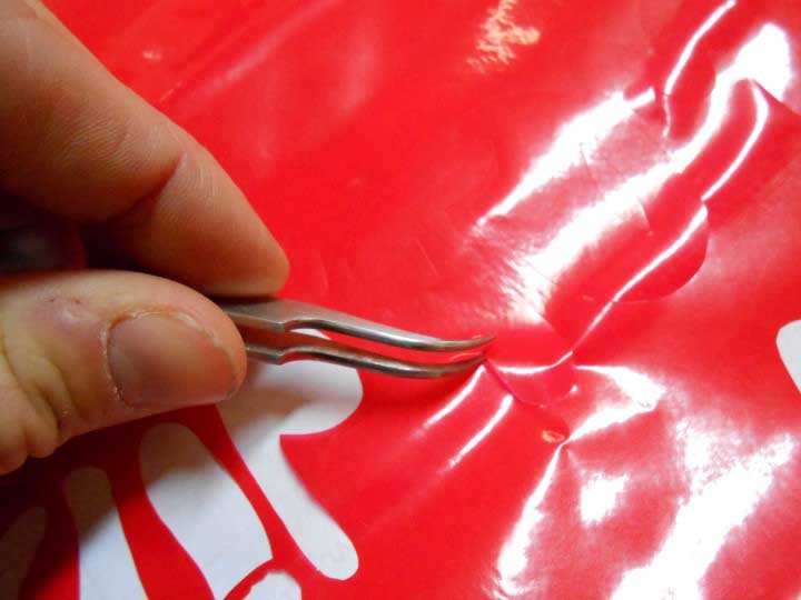
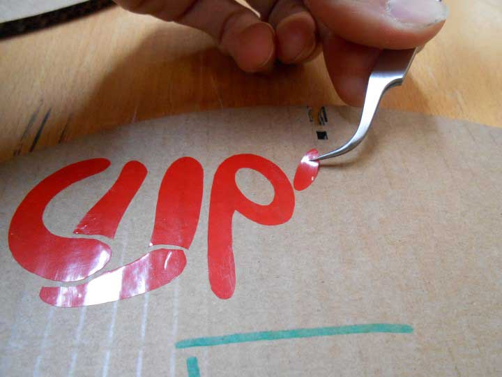
Transfering cut Vinyl onto the cardboard
Here is our Fe atom all tuned up :)

Our "cliptoms" sticker
Hope you enjoyed my Clip'Toms :)
Source Files
Here are the source files :
SolidWorks Assembly filesSolidWorks Part file
Parameters text file
Grasshopper files
Rhino files
Inkscape vinyl cutting files
Conclusion
- Parametric design is vital for making. We always have to do many tries to make thing fit. Redrawing everything each time is not affordable.
- We quickly find that things that don't take time during the test phase, like changing colors of the curves for a cutting strategy, can be very time consuming and brutal if we don't find an automated way of doing so.
- The nesting step can be tricky. In my case it was not so hard since all the shapes were round ! This make nesting choice easier since it's useless trying to rotate the parts for better nesting.
- I'm pretty content with the following workflow : Parametric design in solidworks -> Nesting tool -> Rhino -> grasshopper -> inkscape OR Rhino -> Print or cut
- Note : The export SVG of illustrator is awesome if we can afford it.
***