Week 2
Computer-Aided Design
(CAD)
Assignment
- model (raster, vector, 2D, 3D, render, animate, simulate, ...) a possible final project, and post it on your class page
Week workflow
Here is how I see the week's flow :
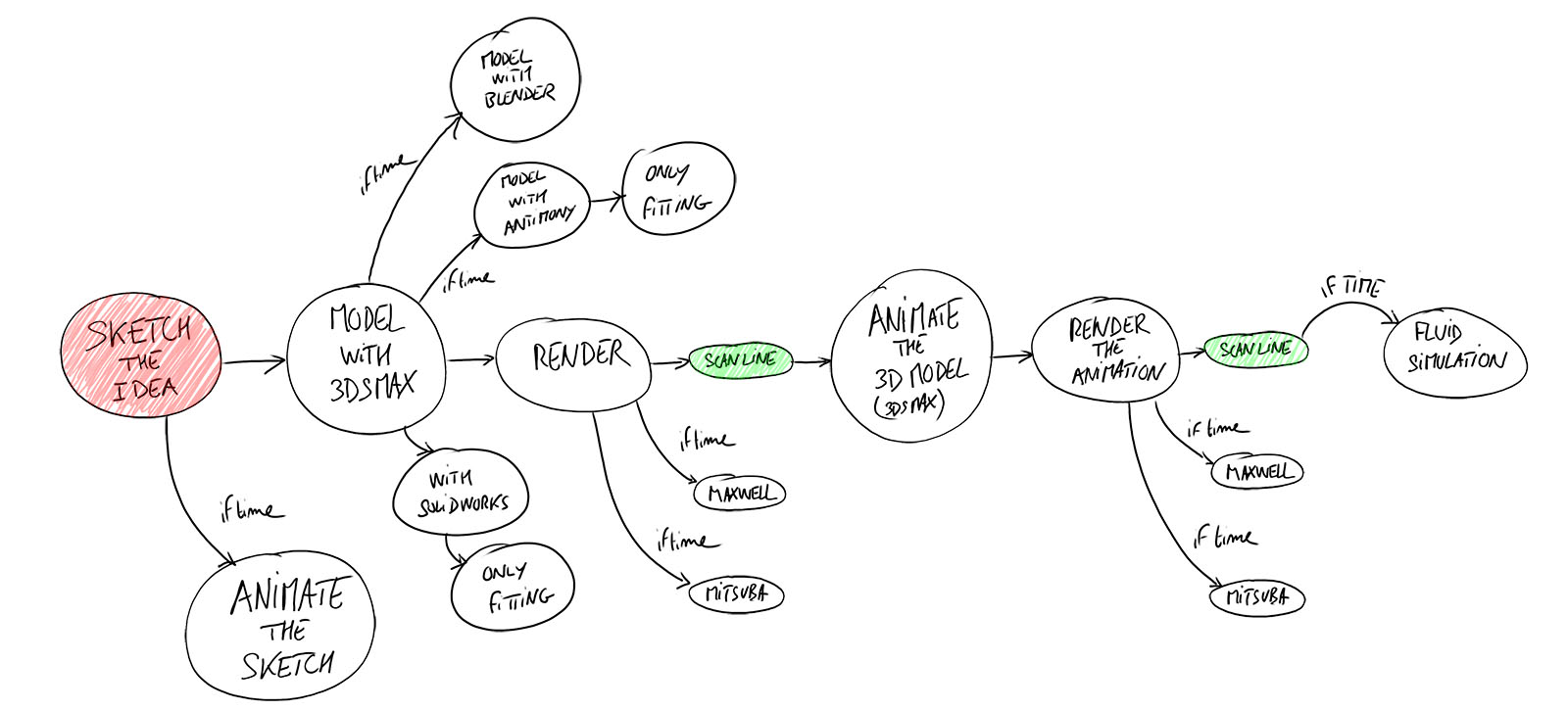
Flow chart for this week
I'm already used to some softwares that could help me do the assignment : Photoshop, 3dsmax, maxwell, Vray
I will start by using them to meet this week requirements.
But, with the time I have left, I will then discover and use new softwares, especially open source ones.
Table of content :
STEPS
2D
I used first Photoshop to make a raster picture of my final project :
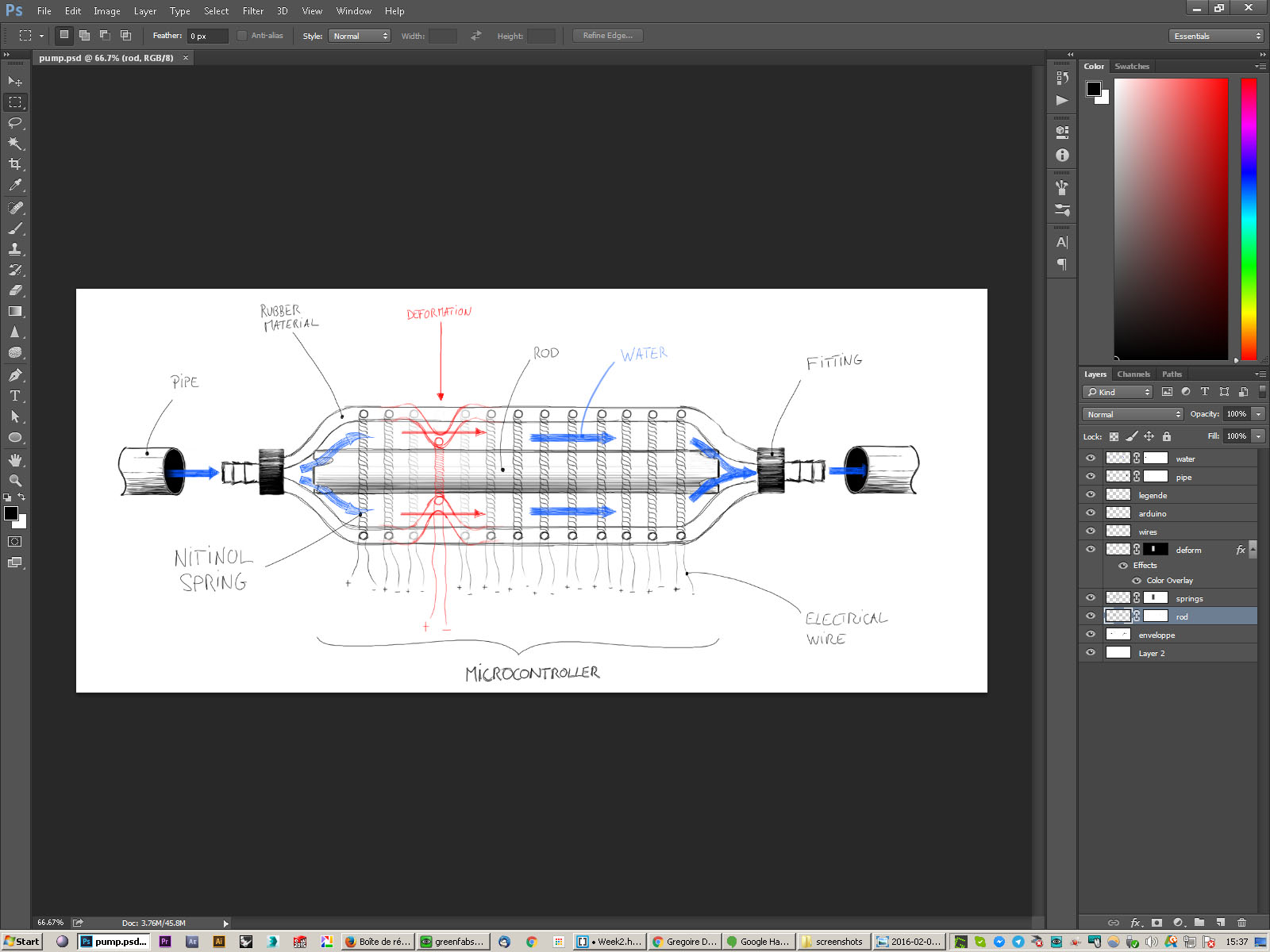
photoshop UI
Using "layers" is useful. It can "separate" your drawing in many different drawings and work on them separately.
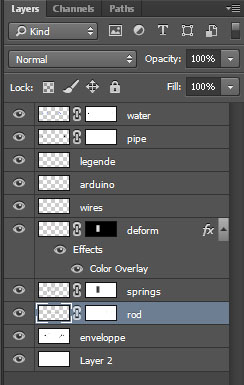
photoshop layers
Once I had this done, I decided to try GIMP, the Free & Open Source alternative for image editing to generate a small 2D animation of the way the pump works.
I generated an animated GIF.
GIMP also gives the ability to use layers. In fact we need this to make an animation.
So I open all my different frames on different layers :
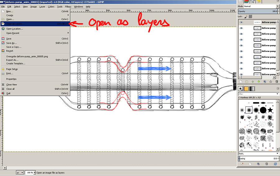
Gimp open as layers
Then we can preview the gif with the playback command :
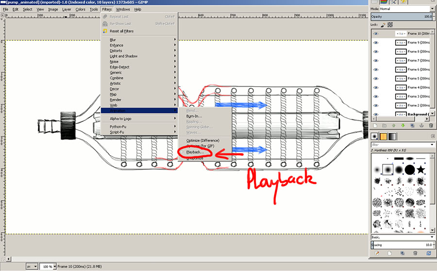
Gimp open as layers
When we're happy, we can export it.
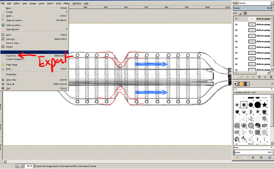
Exporting the Gif
The gif window shows up.
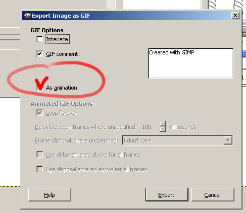
Gif export options
And here is it, the gif put in the html code of this page :

The contraction motion to make the water flow
3D - Polygonal modeling
To "3d sketch" I used 3dsmax. What I mean by 3D sketch is that it is only to be a polygonal ("raster") model
It is useful for quickly "see" in 3D how things can work.
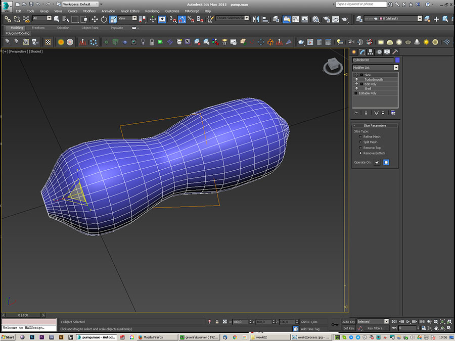
Modeling in 3Dsmax
In 3dsmax, we can see a stack of modifiers that we apply to our model. It is kind of an history, but not as the ones in NURBS modeling softwares.
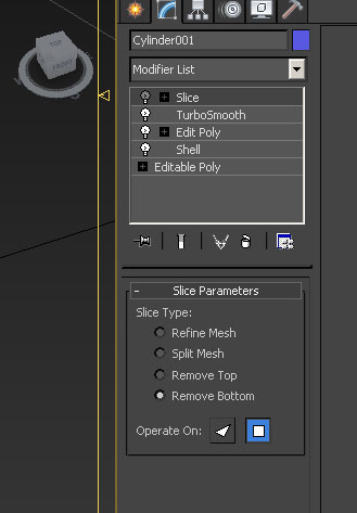
Modifiers stack in 3dsmax
First, for the Nitinol springs, i created a helix.
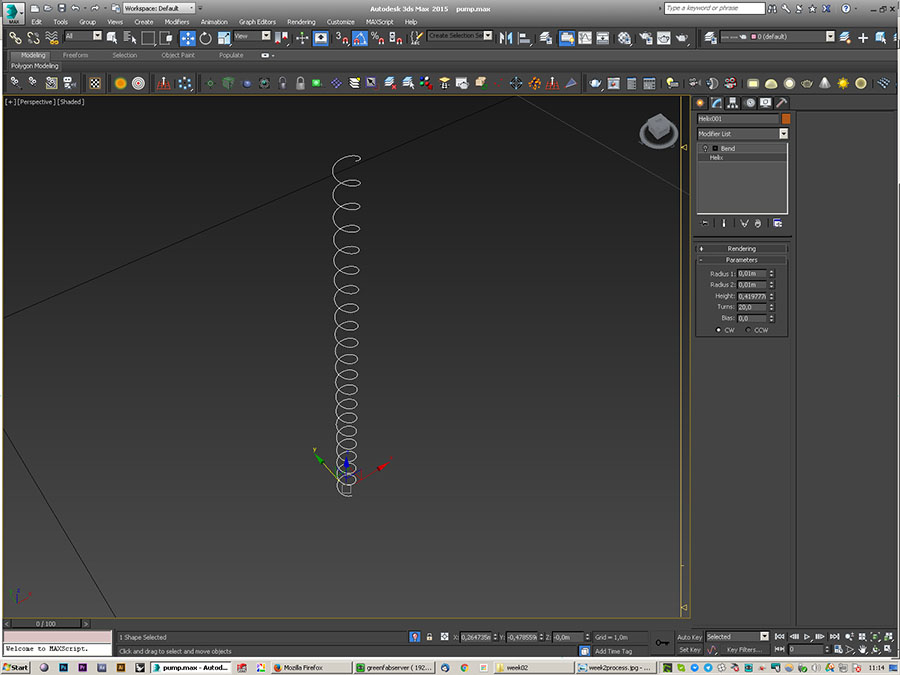
Helix
I use the modifier bend and give it some thickness.
Bend modifier to 360°
I insert it in the membrane.
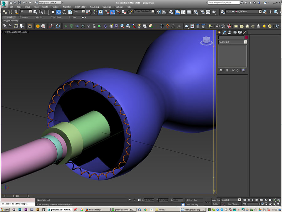
Fitting the spring in the membrane
I then use a world space modifier to easily contract the springs without scaling them (radius of spring stays the same).
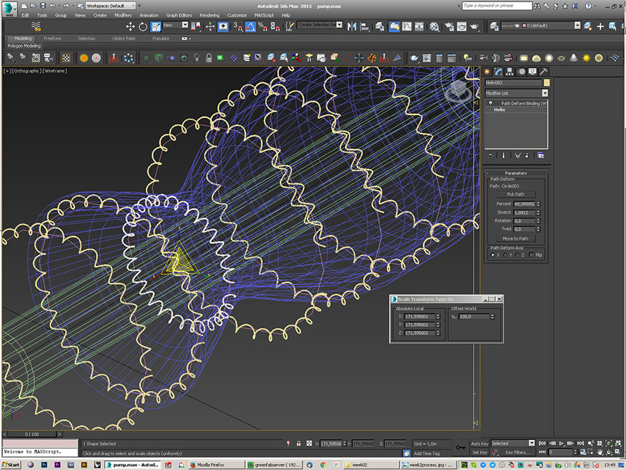
Using world space modifier "path deform"
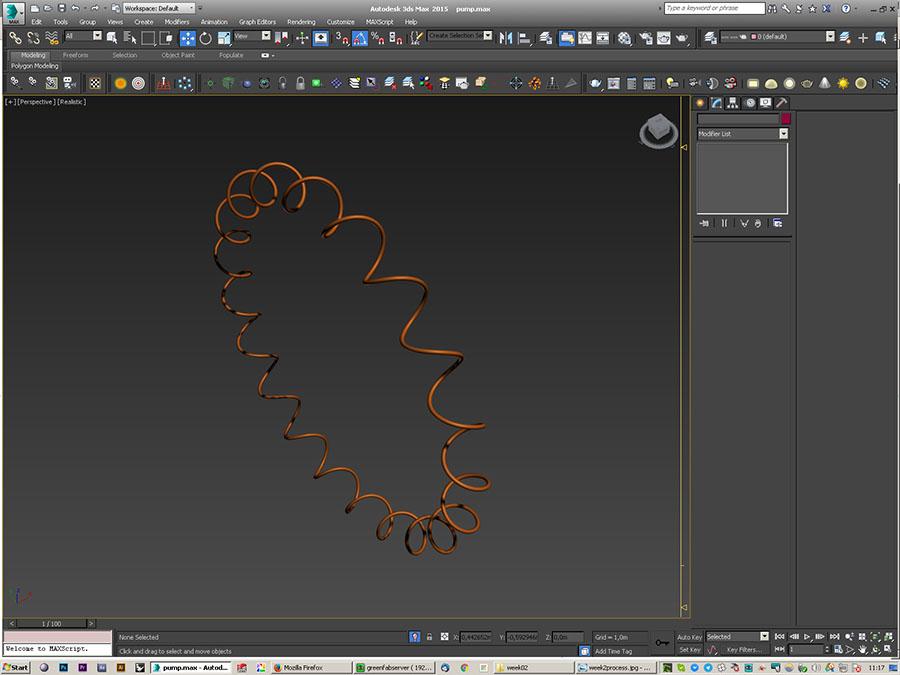
After this I can easily put the different springs along the membrane. For the story, some of these springs are contracted thanks to electricity going through the Nitinol which "remembers" its Austenite state
And there we are, all my springs are set up inside of the membrane.
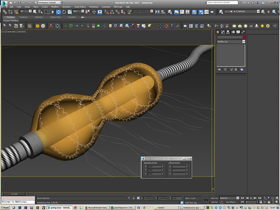
All springs in place
Now I want to add parts that are less organic. Vector modeling software are perfect for this.
I then decided to use Solidworks to do so.
3dsmax file available for download on an external website.
3D - Vector modeling
In Solidworks, we start by drawing vector sketches in 2D. We can add dynamically some dimensions.
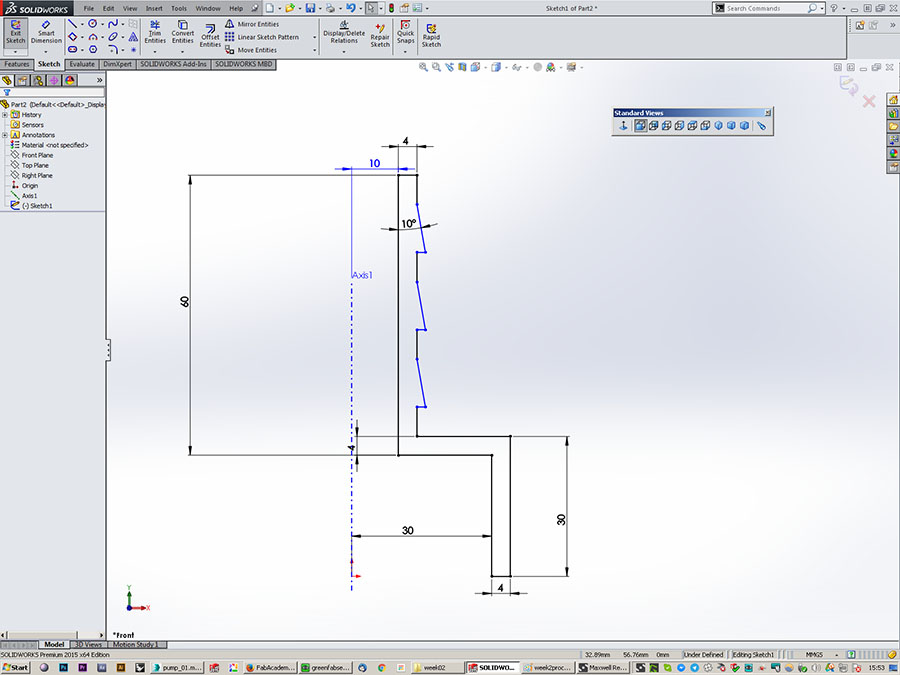
Solidworks UI - sketching
Here are the three objects I modeled : a plumbing fitting, a box to be laser cut, and the internal rod of the pump
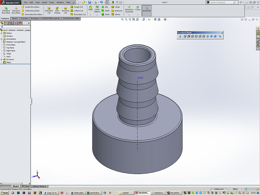
Revolving for the fitting part
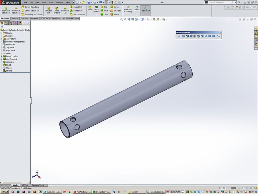
The rod
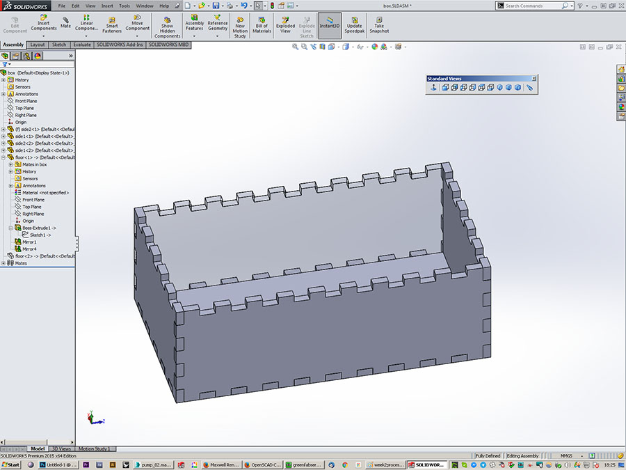
An assembly - the laser cut box
I like to make a small fillet on my edges. That helps the renderers to catch the light
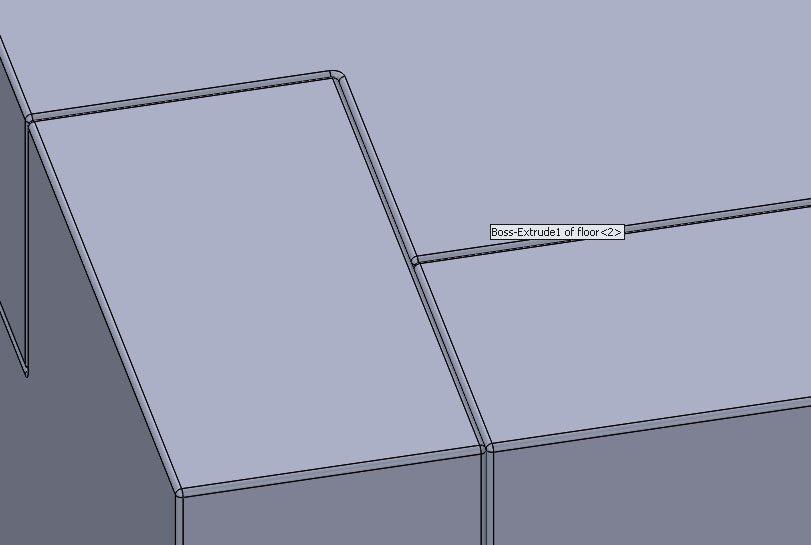
Filleting the edges to catch the light
I can then import these Nurbs models back in 3dsmax with the IGES or STEP format (3dsmax 2015 imports Solidworks files).
The next step is to render !
download Solidworks fitting file
3D - Rendering
Back in 3dsmax we can have a basic render with the "scanline renderer"
3Dsmax scanline rendering
That is not realy pretty. Let's try other renderer.
Renderers are plugins that can be run from the 3D modeling software. Sometimes they also are standalone prgrams, like Mitsuba.
To have a more realistic render, we have to use a render that simulates at least "Global illumination", which is the calculation of the indirect bounces of light in the scene.
Maxwell renderer :
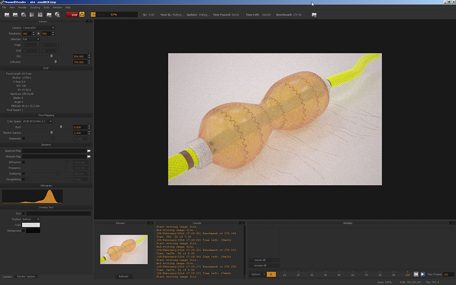
Rendering using Maxwell
Vray renderer :
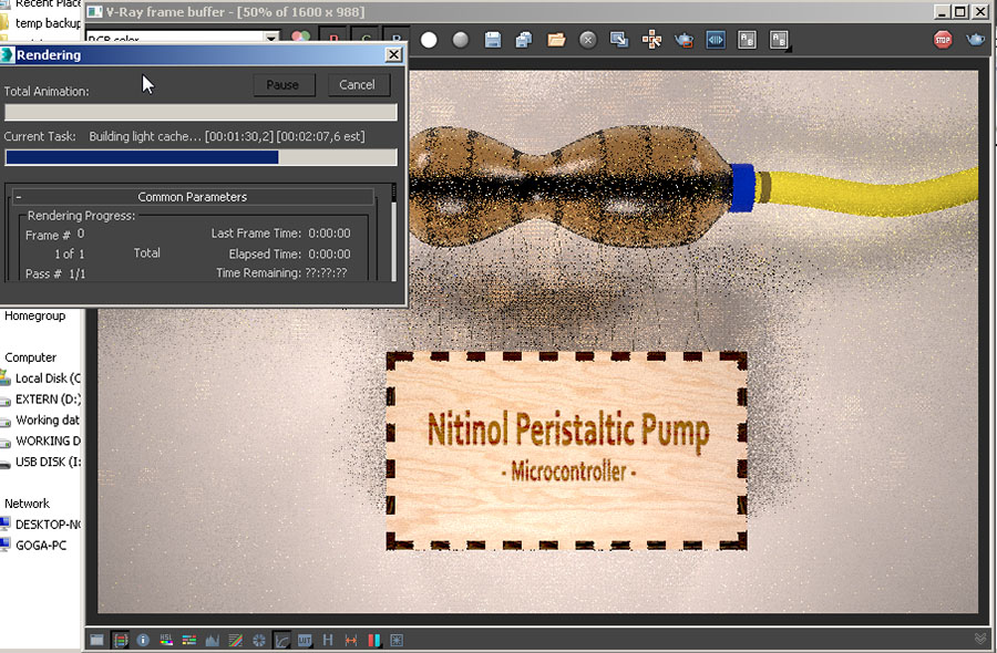
Rendering using Vray
I also tried Mitsuba. I think it's very powerful. I did not have the time to go deeper into it though and I was only able to render one of the sample files.
I did understand that files have to be imported with the obj format and that an xml file is then generated by Mitsuba that describes the scene so that we can work directly in this file.
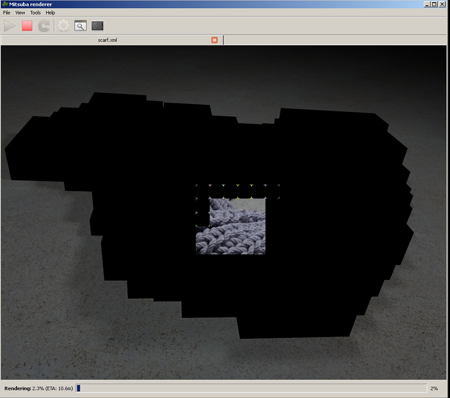
Mitsuba renderer
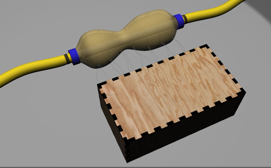
Here is two final rendered images :
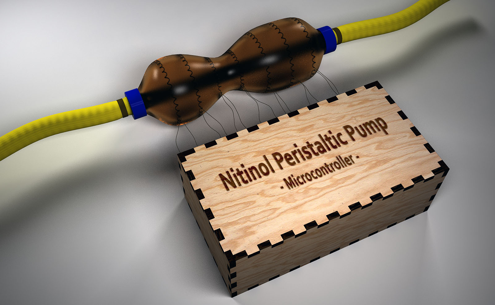
Final rendered image
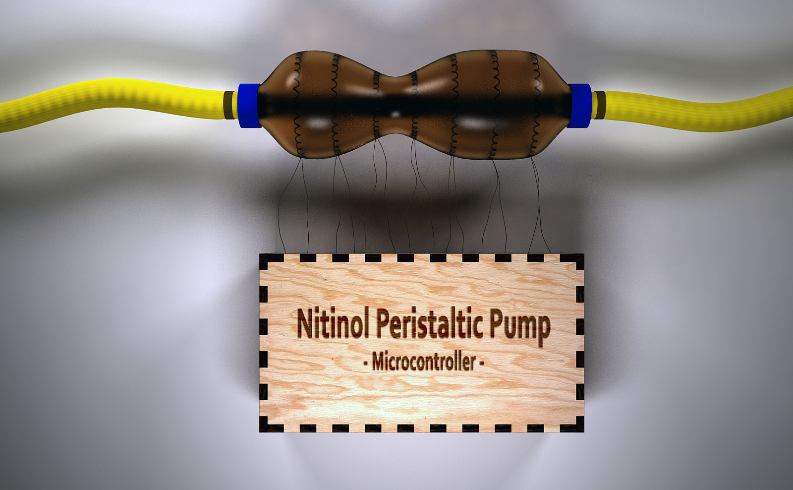
Final rendered image
Antimony
I also wanted to try Antimony.
Since I'm running Windows, I needed to install Virtual box from Oracle (machine virtualization) and Linux. I installed Lubuntu but Antimony wouldn't work on it. I then installed Ubuntu and it worked.
I first had to build Antimony on Ubuntu following the instructions here.
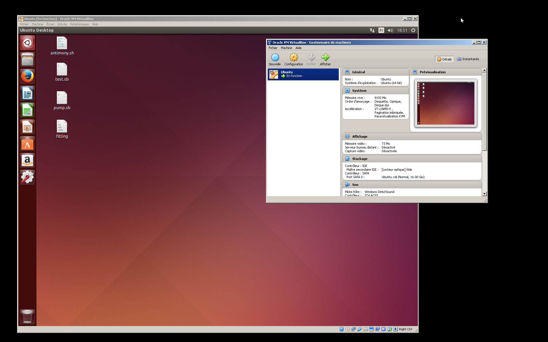
Ubuntu running on windows
So I modeled the fitting.
I find Antimony very promising and powerful for parametric modeling.
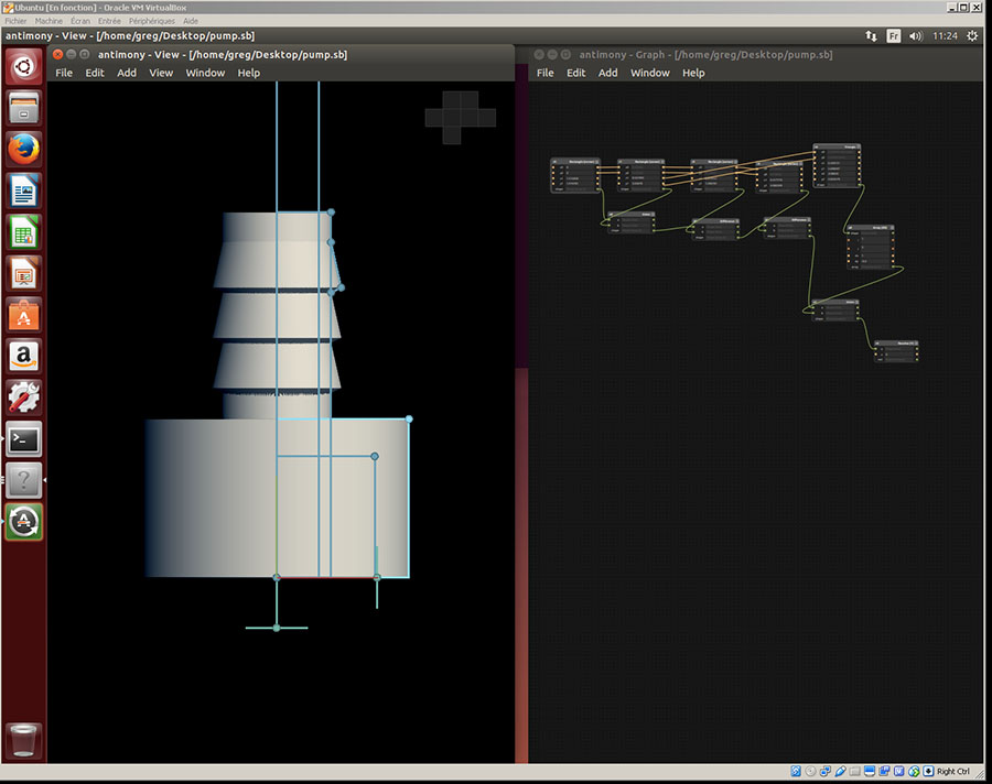
My first antimony model
I'd like to use antimony more for now on. But I also would like to get more information on programming the nodes.
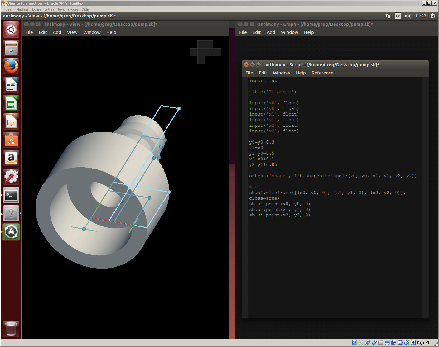
Some very basic antimony parametric modeling with scripting the nodes
I found out that the stl model does not have sharp edge. Is it something that Antimony doesn't know how to do? I'll try to find out.
Conclusion
- During this week I got to use many different 2D and 3D softwares and I understood the fundamental difference between raster works and vector works both in 2D and 3D. I identified which software is better for which kind of work (polygonal for sketching and artistic modeling, and vector for prototyping and manufacturing).
- I would have loved to try Blender as an alternative for 3Dsmax since I'm trying to use as much as I can open source softwares.
- I really liked Antimony and would like to explore in the future ways of scripting it.
***