
3.computer-controlled cutting
This week's assignment
Design, make, and document a parametric press-fit construction kit
This week I tried to make money saving box.
I have used below tools and materials to complete this assignment.
- Software:
- -fusion360(3D parametric design)
- -illustrator(2D design for laser cutting)
- -corel draw(transfer data to laser cutter)
- -Job control(Trotec laser cutter driver)
- -inkscape(2d parametric design, as practice)
- -autocad 123D make(iOS ver. to understand press-fit construction kit)
- Materials:
- -cardboard Thickness=3mm(amazon carton)
- -adhensive vynyl sheet
- -transfer adhensive
- Tools:
- Trotec Speedy100R(Laser cutter)
- Silhouette CAMEO(Vynyl cutter)
- Procedures:
- -Warming Up
- -3D modelling
- -2D layout
- -Laser cutting
- -Assembly
- -Put decals
- Files:
- Appendix:
[Setting]
---Engraving: Power 40/ Speed 70/ 500PPI
---Cutting: Power 20/ Speed 1/ 1000Hz
[Setting]
---Cutting: Silhouette vynyl/Ratchet Blade 1/speed 5cm/s / Thickness 10
Procedures:
Warming Up
As a first step I used autocad 123D Make(iOS ver.) to understand "press-fit construction".
Just draw cross sectional shape on the screen.

123D make will generate waffle structures.
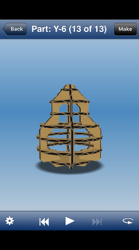
Easily output pdf file for cutting.
I realized slit length should be half of parts width.

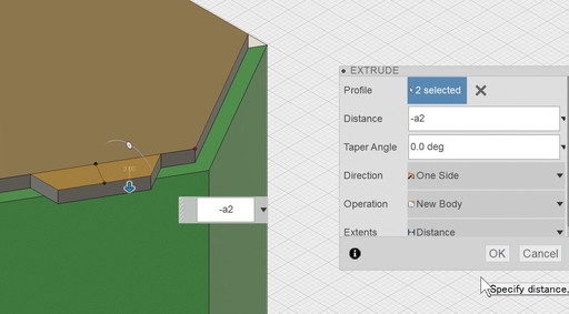
3D Modelling
Then I started to draw money saving box by using fusion360
Simply draw 3D image, extrude hexagon.

Sketch and modified details.(made press-fit structure)

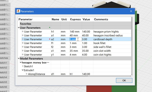
One of the most important thing for this assignment is to make parametric design.
all parameters must be changeable. To do this I used "parameter features"(Menu Modify>change parameters)

All parameter has been assigned own parameters

So that change figures by just input numbers
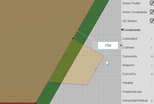
Especially need to consider cardboard thickness, so that user can use any different material.
Parameter lists. Changing values in this area can apply for all linked dimensions. No need to change one by one. Very convenient!
Changing parameters! BEFORE---------AFTER
.jpg)
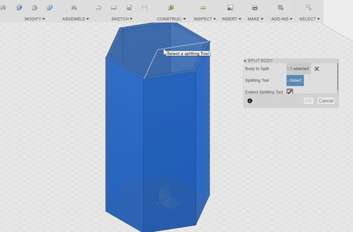
To make separated parts, used "split body" feature
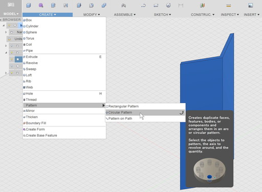
Side parts are separated. Use "circular pattern" to make 2 more same parts.
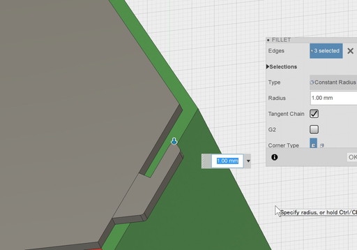
For easily assembling, chamfer joint's corner.
Exploded image

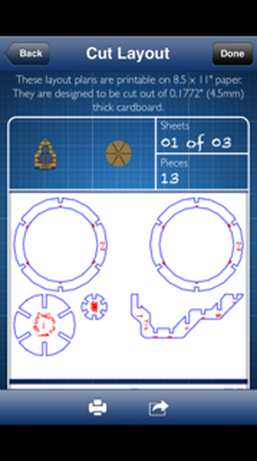
For laser cutting, need 2D data.
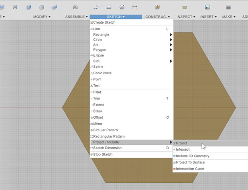
This time I used "project" feature
[Update!]found no project needed. What need to is just create sketch and select a surface. It's enough to get 2d data.
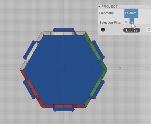
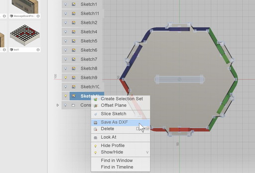
Export 2d data as "dxf"
-2D layout
2nd step is 2D layout. Using illustrator.
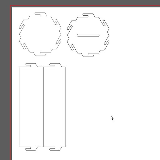
This time I used "kerf bending" for 3-side corners.
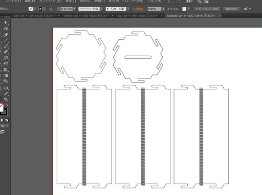
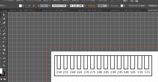
Making gap gauge, to find better fitting
-Laser cutting
Open pdf data in CorelDraw(this Win PC is connecting laser cutter)
.jpg)
Change cutting line as Red(255.0.0),extra-fine line
.jpg)
This time I used Trotec Speedy100R
.jpg)
Adujst cutting/engraving power and speed
.jpg)
Cutting Gap Gauge
.jpg)
Cutting power seemed just, no burning
.jpg)
Searching appropriate gap, material was 3mm thick cardboard. found 2.2mm gap was tight enough

Cutting parts
.jpg)
However "karf bending" was too crowded, back side was burning. Adjust Laser power from 30 to 20.
.jpg)
Adjusted each lines gap, more space may resolve the problem.
.jpg)
After 1st assembly test, found "tab" was too narrow and easily deformed, changed thickness from 2.2mm to 2.6mm.
.jpg)
Adjusted tab height, just need to change parameter(2*thick>>3*thick)
.jpg)
Cut again
.jpg)
Movie
Completed!
.jpg)
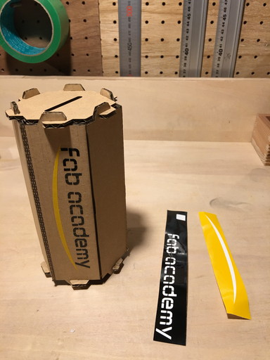
-Assembly
All parts are ready.
.jpg)
Gently bend "karf bending"
.jpg)
Assmbly parts piece by piece.
.jpg)
To assemble properly, hold 2 tabs with fingers.
.jpg)
Just remain one side part.
.jpg)
One side completed.
.jpg)
Another side by same way. Assemble slowly and carefully.
.jpg)
Top view
.jpg)
Finished! Put some coins.
.jpg)
Movie
-Put decals
Draw decal design by using Silhouette Studio

Adjust cut depth appropriately

Cutting...
This time I selected fab font.

As decals were separated with small parts, needed to use adhensive sheet.

Remove decals slowly.

Carefully
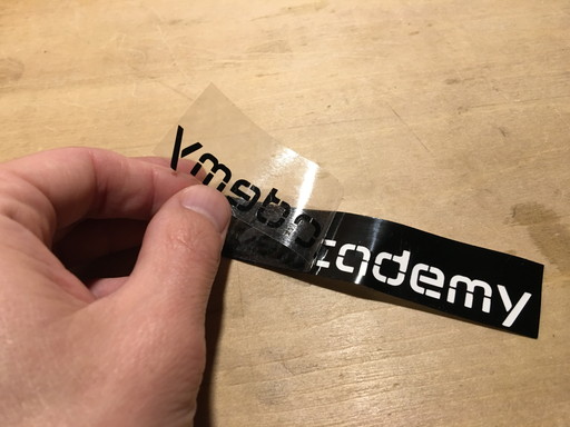
Put on the box

Stick tightly and remove adhensive sheet.
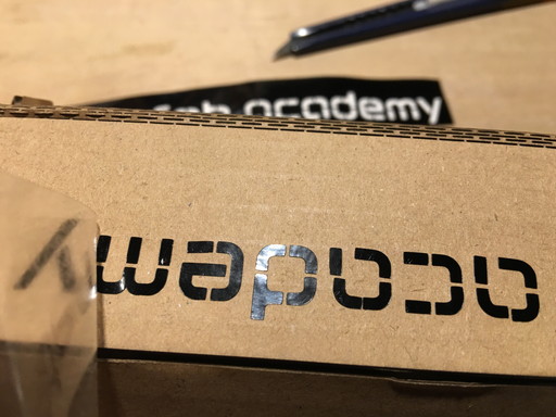
Finished!

Movie
Files
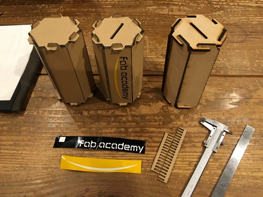
Appendix
Tried to use MDF material(5mm).
.jpg)
"karf bending" was cracked. Possible reason were material thickness was too large and karf bending width was not enough.
.jpg)
One design may not applicable for all materials. Design needs to suit fot each material's perperty.
.jpg)
Brothers
Inkscape(parametric design practice)
Draw a slit and Edit>Clone>Tiled Clones
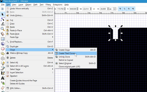
Put clones in each sides.
.jpg)
Changing Parent can apply for all linked clones.
.jpg)