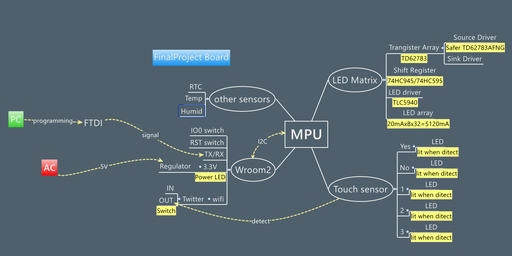
There are some functions and need to build several boards. Aiming for testing and development, prototyping boards before making final version.
1.Communication
Test ESP8266 and send message to twitter
For wireless communication, I select famous wifi module ESP8266. As for certification issue, we must use WROOM2(=ESP8266) in Japan.
As this is my first time to use ESP8266, I have learned there are 2modes.
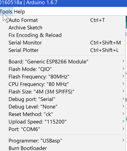
Testing AT command need to use original firmware. And if use as Arduino like board, pull down IO_0.
[Use AT command, need to reflash firmware with ESP FLASH DOWNLOAD TOOL]
[ESP8266 can run as Arduino board]
To send/receive message via internet, there are some Twitter API such as IFTTT, ThingSpeak or StewGate.
This time I tried StewGate and get twitter token.
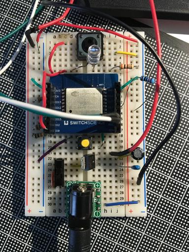
[Messy prototyping board]
[Success to send messange when pressing button]
This prototyping and PCB are covering Week15"Network and communications".
2.LED Matrix display
Test LED matrix display to show characters
Most of things are first time for me. To understand LED matrix(dynamic lighting) I refferd this site.
When wiring each pin, need to think which one is anode and cathode.
Delay very short time(like 0.1) seems all LEDs lighting at the same time.
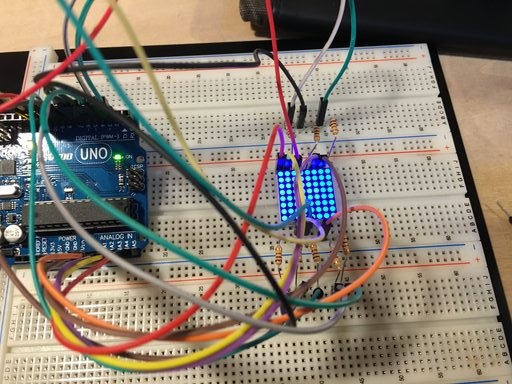
[Messy prototyping board again.]
[To show characters, need to prepare font data.]
[I want to make larger display.]
To make larger display, need to cascade some modules. As the time was very limited I decided to use max7219 display driver instead of
making original PCB to control many LED's , so that saving time, money and also make things simple and reliable.
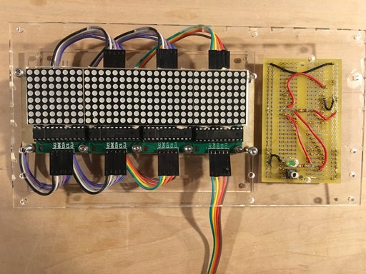
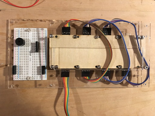
[Front side of LED matrix display]
[Back side of LED matrix display]
3.Connect more than 2 processors
Connect ESP8266 and AVR board
LED matrix and other features need many IO ports, but ESP8266 doesn't have so much ports. As the result necessary to use more than 2 processors.
Originally I planned to connect ES8266 board(wifi feature) and other features with AVR board(like ATmega328).
Then I could found max7219 LED display driver and possible to reduce the nuber of pins(just 3pin to control LED matrix) dramatically.
And also almost run out of time to make another board, so finally I decided to use same ESP8266 board for wifi and other features , as using two ESP8266 can cover necessary IO ports.
Board A for wifi(receive twitter timeline), LED matrix,buzzer, Board B for wifi(send message), LED indicator and switch(instead of touch sensor).
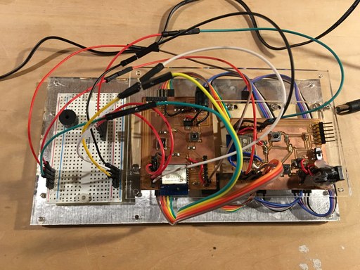
Those two ESP8266 board are independent currently.
[I made two ESP8266 PCB boards, there are too many lines need to be organized.(I used Tie-wraps)]
4.Make Touch sensor switches
To make this feature happen, I just use Week11's touch sensor.
I used Arduino to make prototyping and it worked well. Especially I changed to large 8.2M Ohm resistor and it worked at high sensitivity.
Though prototyping worked well with Arduino Uno but differ in ESP8266 so I gave up to use touch sensor and changed to tactile switch temporary.
5.Get twitter timeline
To get twitter time line, I used different way from sending message(stewitter).
It need below outside services and a little complicated.
-IFTTT
-Maker channel
-Beebotte
To implement this feature, I refferd from this site(Japanese).
[IFTTT Maker channel setting, there are so many things I can try.]
I succeeded to implement touch switch in the bread board + Arduino prototyping. However it didn't work
with ESP8266. I changed to very large resister(such 20-30MΩ) but result was the same. So currently use tactile switch instead of touch sensor. I would like to find the root cause and improve in the future.
Apart from above, I would like to change the boards more simple. Maybe ESP8266 + ATmega328 system put in one board and connect those CPUs each other.
Finally I need to support KANJI(Japanese and Chinese characters), so that my family can understand message more easily. It may need external EEPROM.


